#applications of ohms law
Text
Advantages of Merchant Processing over Direct Carrier Billing in Mobile Commerce
#unveiling va benefits in seattle washington#unveiling#solar power#the philosophy of stoicism#lucid air unveiling#prayer for a change of story#how i pick the best stocks: investing for beginners#power rangers thunder storm#the secret rules rich people use to get richer#prayer for restoration of relationship#power calculations#future of materials#the truth about temu#the truth about temu i wish i knew this sooner#limitations of ohm's law#applications of ohms law
1 note
·
View note
Text
Ohms Law and Its Application in Electrical Engineering
Ohms Law and Its Application in Electrical Engineering
youtube
View On WordPress
#Aplicación de Ingeniería Eléctrica#career choice#carreras universitarias#Electrical Engineer#Ohms Law Application in Electrical Engineering#Youtube
0 notes
Text
Reading more about inrush current control techniques now, all I knew before this was that you use Negative Temperature Coefficient parts to control it without affecting overall efficiency too much.
I've never had to design a board that drew much power, or didn't just use an off the shelf power supply. Power supply design is black magic so even major companies usually just buy certified open frame units to avoid redoing a ton of regulatory work, it's what's best for everyone. All the appliances at First Job just had a 24V Great Wall open frame units jammed in there, plus consumer 12V supplies for the network gear.
You can do some clever things involving having the NTC take itself out of the loop with a relay and a zener diode if you have really high efficiency targets to hit or you don't want to fry your NTC as the current picks up. I love these kinds of self-contained feedback tricks, they're super handy. And of course there's digital current controllers for high precision applications.
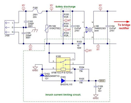
Figure 5 shows the relay circuit for a 1kW power supply. The relay is initially turned off. During power up, the input current flows through a 10Ω/10W cement resistor. Once the power supply is energized, a regulated bias voltage, 12V2, turns on the relay to minimize the power dissipation on the current-limiting circuit during normal operation.
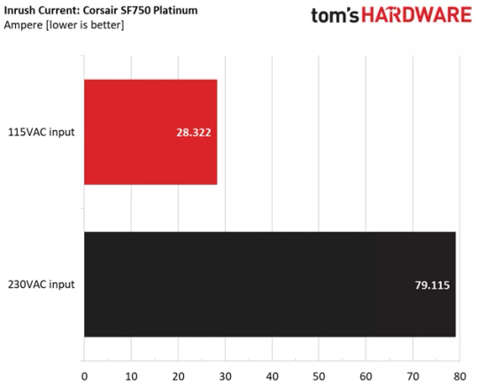
Anyway. Reading specs it looks like there's a systematically higher inrush current in computer PSU's when you connect them to 230V, which is probably just Ohm's Law at work. A lot of supplies with really good 110V inrush limiting have utterly dogshit 230V inrush limiting.
An interesting problem I realize this might cause is that, because most tech reviewers are Americans with 110V, they won't pick this up as often. E.g. the highly recommended SF750 from Corsair has fantastic 120V inrush of ~30A but on 230W it's almost 80A, which would definitely trip a lot of home breakers.
10 notes
·
View notes
Text
What are the Limitations and Applications of Thevenin Theorem?
Thevenin’s Theorem states that any linear electrical network can be replaced by an equivalent circuit consisting of a single voltage source in series with a resistor. This equivalent circuit accurately models the original network’s behavior as seen from a specific pair of terminals.
Explaining Thevenin’s Theorem
In essence, Thevenin’s Theorem allows us to simplify complex circuits by finding an equivalent Thevenin voltage and Thevenin resistance. This makes circuit analysis more manageable and enables us to predict how the circuit will respond to different loads.
Imagine you have a complex electrical circuit with multiple components like resistors, voltage sources, and current sources. Thevenin’s Theorem allows you to condense this complexity into a simpler representation of a Thevenin equivalent circuit while preserving the original circuit’s behavior between two terminals.
To apply Thevenin’s Theorem, follow these steps:
Identify the terminals: Determine the two terminals (let’s call them A and B) across which you want to simplify the circuit.
Calculate Thevenin Voltage (V_th): Disconnect the load connected across A and B. Calculate the open-circuit voltage (V_th) across terminals A and B.
Calculate Thevenin Resistance (R_th): Turn off all independent sources (voltage and current sources) and calculate the equivalent resistance looking back into the circuit from terminals A and B.
Thevenin’s Theorem Statement and Proof
The statement of Thevenin’s Theorem can be summarized as follows:
The formal statement of Thevenin’s Theorem is as follows: “Any linear electrical network containing independent and dependent sources can be replaced by an equivalent circuit consisting of a single voltage source (Vth) in series with a single resistor (Rth). This equivalent circuit is valid only at the terminals of interest.
Thevenin’s Theorem Derivation
To derive the Thevenin equivalent circuit, we start by removing all sources in the original circuit and determining the voltage across the terminals of interest. Then, the circuit is simplified to find the Thevenin resistance. This step-by-step process results in the derivation of the Thevenin voltage and resistance.
To derive Thevenin’s Theorem formula, we start by considering a complex circuit with multiple elements. By progressively simplifying this circuit, we ultimately arrive at the Thevenin equivalent circuit. The process involves finding the open-circuit voltage and the short-circuit current, which serve as the basis for determining Vth and Rth respectively.
Finding Open-Circuit Voltage (Voc): We disconnect the load from the original circuit and measure the voltage across its terminals. This voltage is the open-circuit voltage.
Finding Short-Circuit Current (Isc): We short-circuit the load terminals and measure the current flowing through the circuit. This current is the short-circuit current.
Calculating Vth:The open-circuit voltage directly translates to Vth as there is no current flowing through the load.
Calculating Rth: By applying Ohm’s Law (R=V/I ), we divide the open-circuit voltage (Voc) by the short-circuit current (Isc) to obtain Rth
Thevenin’s Theorem Proof
The proof of Thevenin’s Theorem is based on the superposition principle and the linearity of circuits. By analyzing the behavior of the original circuit with different independent sources, we can demonstrate how the Thevenin equivalent circuit accurately represents the network.
Thevenin Theorem Examples
Example 1: Consider a circuit with a voltage source of 12V and a resistor of 4Ω. By applying Thevenin’s Theorem, we can determine the equivalent voltage and resistance to simplify the analysis.
Example 2: In a more complex circuit with multiple sources and resistors, Thevenin’s Theorem offers a straightforward way to predict the circuit’s behavior under different conditions.
Limitations of Thevenin Theorem
While Thevenin’s Theorem is a powerful tool for circuit analysis, the following are a few limitations,
Applicable only to linear networks (those obeying Ohm’s Law).
Assumes networks are time-invariant (constant parameters over time).
Might not be suitable for circuits with non-linear components like diodes or transistors.
Major Applications of Thevenin Theorem
Here are a few major applications of Thevenin’s Theorem,
Circuit design: Thevenin’s Theorem is used to simplify complex circuits during the design phase.
Fault analysis: By applying Thevenin’s Theorem, engineers can identify faults and troubleshoot electrical networks more efficiently.
Simulation and modeling
System optimization
Fault diagnosis
Understanding Thevenin’s Theorem is essential for electrical engineering students and professionals alike. By mastering this concept, you can streamline circuit analysis and design processes, making your work more efficient and effective.
This article discusses in-depth Thevenin’s Theorem along with Thevenin’s Theorem examples and Thevenin’s Theorem formula further exploration of related concepts, please visit our blog section. If you seek personalised online tuition, Tutoroot offers exceptional physics online tuition services to address any queries you may have. Book a FREE DEMO session by clicking here.
0 notes
Text
Harnessing the Power of Operational Amplifiers in Analog Design
Analog and signal circuit design is essential for countless electronic devices, ranging from smartphones and computers to medical instruments and automotive systems. Though digital technology often holds the utmost significance, analog circuits are necessary for processing and transmitting real-world signals with precision and efficiency. Please check out this post and understand the fundamentals of analog and signal circuit design, exploring their significance and applications.
Understanding Analog Circuit
Analog circuits are electronic circuits that process continuous signals like voltage or current whereas the binary values represent the discrete digital signals. These circuits manipulate analog signals in different ways, including amplification, filtering, modulation, and conversion. Analog circuits are specifically characterized by their ability to represent and manipulate real-world phenomena accurately. That’s why these circuits are essential for applications that require precise signal processing.
Important Principles of Analog Circuit Design
An analog circuit design requires a deep understanding of fundamental principles and components. Some important concepts include:
Ohm's Law – This law describes the relationship between voltage, current, and resistance in a circuit.
Kirchhoff's Laws – These laws administer the behavior of current and voltage in electrical circuits, including Kirchhoff's Current Law (KCL) and Kirchhoff's Voltage Law (KVL).
Component Characteristics – They allow you to understand the behavior of passive components like resistors, capacitors, and inductors, as well as active components like transistors and operational amplifiers (op-amps). These components are important for analog circuit design.
Frequency Response - Analog circuits work within certain frequency ranges and require the consideration of frequency-dependent effects like bandwidth, phase shift, and frequency response.
Understanding Signal Circuit Design
A signal circuit focuses on signal transmission and processing that can range from audio and video signals to sensor data and communication signals. These circuits are essential for various applications, including telecommunications, audio processing, instrumentation, and sensor interfacing. Signal circuit design covers different techniques and components tailored to specific signal processing needs.
Applications of Analog and Signal Circuit Design
There are so many applications of analog and signal circuit design in numerous industries and technologies:
Audio Amplification - Analog circuits are useful in audio amplifiers to enhance the amplitude of audio signals for speakers, headphones, and other audio devices.
Data Acquisition - Signal circuits are used in data acquisition systems to convert analog signals from sensors and transducers into digital data for processing and analysis.
Wireless Communication - Analog circuits are integral aspects of wireless communication systems, including radio frequency (RF) transmitters, receivers, and modulators/demodulators.
Medical Instrumentation - Analog circuits are applicable in medical devices like electrocardiographs (ECGs), ultrasound machines, and blood pressure monitors for processing and analyzing signals.
Automotive Electronics - Analog circuits are also used for automotive systems for applications like engine control, vehicle diagnostics, and entertainment systems.
Conclusion:
Analog and signal circuit design is the fundamental aspect of electrical engineering that enables the precise processing and transmission of real-world signals in a comprehensive range of applications. Using fundamental principles, components, and design techniques, Voler Systems engineers can provide analog circuit design services to accommodate the diverse demands of modern technology. Though digital systems continue to advance, the importance of analog and signal circuit design remains paramount, integrating the physical world into the digital counterpart smoothly and effortlessly.
1 note
·
View note
Text
Class 12 Current Electricity: Definition, Generation, Types and Working
Introduction:
Current electricity is a fundamental concept in physics, dealing with the flow of electric charge through a conductor. It forms the basis of various electrical devices and systems that we encounter in our daily lives.

Definition:
Current electricity refers to the movement of electric charge through a conductor. It is typically measured in amperes (A), with one ampere representing the flow of one coulomb of charge per second.
Types of Current Electricity:
1. Direct Current (DC): In DC, the flow of electric charge is unidirectional, meaning it travels in one direction only. Batteries and cells are common sources of DC.
2. Alternating Current (AC): AC reverses direction periodically, creating a waveform. This type of electricity is commonly used in households and industries. It's the primary form of electricity transmitted over long distances.
Generation of Electricity:
Electricity can be generated using various methods, including:
1. Electromagnetic Induction: This principle is used in generators to convert mechanical energy into electrical energy. When a conductor moves within a magnetic field, it induces an electric current in the conductor.
2. Chemical Reactions: Batteries and cells generate electricity through chemical reactions. In these devices, chemical energy is converted into electrical energy.
3. Photovoltaic Effect: Solar cells generate electricity when exposed to sunlight. The photovoltaic effect in these cells converts light energy directly into electrical energy.
Working Details:
1. Conductors and Insulators: Materials that allow the flow of electric charge are called conductors (e.g., metals), while those that restrict the flow are insulators (e.g., rubber, glass).
2. Ohm's Law: Ohm's law states that the current flowing through a conductor is directly proportional to the voltage across it, given a constant temperature. It's represented as I = V/R, where I is current, V is voltage, and R is resistance.
3. Resistors: Resistors are components used to control the flow of current in a circuit. They offer resistance to the flow of electric charge and are essential for regulating current in electrical circuits.
4. Circuit Components: Various components such as capacitors, inductors, diodes, and transistors play crucial roles in electrical circuits, enabling functions like energy storage, signal processing, and amplification.
Understanding Class 12 Physics current electricity is vital for comprehending the functioning of electrical systems, from simple circuits to complex power grids. It forms the backbone of modern technology and has a wide range of applications in different fields.
0 notes
Text
How to bias a Zener diode?
Biasing a Zener diode is a key aspect to ensure it operates effectively. Here's a simple guide:
Understand Zener Diode: First off, grasp the concept of a Zener diode. It's a semiconductor device designed to operate in the breakdown region, allowing it to maintain a constant voltage across its terminals when properly biased.
Choose a Resistor: To bias a Zener diode, you'll need a resistor in series with it. This resistor limits the current flowing through the diode and helps to stabilize its voltage.
Calculate Resistor Value: Determine the appropriate resistor value using Ohm's law. The current flowing through the Zener diode (Iz) can be calculated as the difference between the supply voltage (Vs) and the Zener voltage (Vz), divided by the desired current through the diode (Iz = (Vs - Vz) / Iz). Choose a resistor value (R) that limits this current to a safe operating level for the Zener diode.
Connect in Series: Connect the Zener diode in series with the resistor. Ensure the polarity of the diode is correct; the cathode should be connected to the positive terminal of the power supply.
Apply Power: Apply power to the circuit. The Zener diode should now be biased, maintaining a constant voltage across its terminals.
Test and Adjust: Measure the voltage across the Zener diode to ensure it's operating at the desired voltage. If necessary, adjust the resistor value to fine-tune the voltage.
Consider Temperature: Keep in mind that the voltage across a Zener diode can vary with temperature. For precise applications, temperature compensation techniques may be required.
By following these steps, you can effectively bias a Zener diode and ensure stable voltage regulation in your circuit.
0 notes
Text
What is a PT100 Temperature Sensor and How Does It Work?
A PT100 temperature sensor is a type of resistance temperature detector (RTD) known for its high accuracy and stability in measuring temperature. It is widely used in various industries and applications where precise temperature monitoring is essential. Let's delve into what a PT100 temperature sensor is and how it works.
What is a PT100 Temperature Sensor?
A PT100 temperature sensor is a type of RTD that uses a platinum (Pt) wire as its sensing element. The "100" in its name refers to the resistance of the sensor at 0°C, which is approximately 100 ohms. The PT100 sensor operates on the principle that the resistance of a metal, in this case, platinum, changes with temperature in a predictable and linear manner.
How Does a PT100 Temperature Sensor Work?
The working principle of a PT100 temperature sensor is based on the relationship between the resistance of the platinum wire and the temperature it is exposed to. As the temperature changes, the resistance of the platinum wire changes accordingly.
At 0°C, the resistance of the PT100 sensor is precisely 100 ohms (hence the name PT100). As the temperature increases, the resistance of the platinum wire increases linearly with temperature. This relationship follows the international standard defined by the International Electrotechnical Commission (IEC) known as the Callendar-Van Dusen equation.
To measure the temperature using a PT100 sensor, a constant current is passed through the platinum wire, and the voltage drop across the sensor is measured. Using Ohm's law (V = IR), the resistance of the sensor can be determined from the measured voltage and known current. By knowing the resistance of the PT100 sensor, the temperature can be accurately calculated using standardized temperature-resistance tables or mathematical equations derived from the Callendar-Van Dusen equation.
One of the key advantages of PT100 temperature sensors is their high accuracy and repeatability across a wide temperature range. They offer better stability and linearity compared to other types of temperature sensors, making them ideal for applications where precise temperature measurement is critical, such as industrial processes, laboratory experiments, HVAC systems, and environmental monitoring.
In conclusion, a PT100 temperature sensor is a highly accurate and reliable device used for measuring temperature based on the resistance-temperature relationship of a platinum wire. Its robust construction, excellent accuracy, and linear response make it a preferred choice for various temperature sensing applications across different industries.
0 notes
Text
Unveiling the Power of Resistors: From Discovery to High Power Solutions
Resistors, the unsung heroes of electrical circuits, play a crucial role in controlling current flow, voltage levels, and signal processing. Among the myriad types available, aluminium resistor and ceramic resistor stand out for their distinct properties and applications. But before delving into their specifics, let's journey back to the origins of the humble resistor.
The discovery of the resistor can be traced back to the pioneering work of scientists like George Simon Ohm in the early 19th century. Ohm's law laid the foundation for understanding the relationship between voltage, current, and resistance, essential for the development of electrical components. While the exact individual credited with the discovery of the resistor remains ambiguous due to its fundamental nature, the collective efforts of physicists and engineers over centuries have propelled its evolution.
Fast forward to the modern era, and high power resistors have become indispensable in various industries, from telecommunications to automotive engineering. These robust components are designed to withstand high levels of power dissipation, ensuring reliability and stability in demanding applications.
Enter Powerresistor, a prominent name in the realm of resistive technology, headquartered in New Delhi. With a commitment to innovation and quality, Powerresistor has been at the forefront of providing cutting-edge solutions for diverse industrial needs. Their expertise in manufacturing aluminium resistors and ceramic resistor has garnered acclaim for delivering superior performance and durability.
Aluminium resistors, known for their lightweight yet durable construction, find extensive use in electronic devices, power supplies, and automotive systems. Their high thermal conductivity and corrosion resistance make them ideal for applications where reliability is paramount.
On the other hand, ceramic resistors offer exceptional stability and precision, making them suitable for high-frequency circuits, RF amplifiers, and medical equipment. Their non-inductive properties and high insulation resistance ensure minimal signal distortion and accurate impedance matching.
who discovered resistor it's optimizing power distribution, maintaining circuit integrity, or ensuring signal fidelity, the role of resistors cannot be overstated. From the early days of scientific inquiry to the advanced solutions of today, these indispensable components continue to shape the landscape of modern technology.
In conclusion, while the discovery of the resistor may be shrouded in historical ambiguity, its impact on contemporary engineering and innovation is undeniable. With companies like Powerresistor leading the charge in developing high-quality aluminium resistors and ceramic resistors, the future of resistive technology looks brighter than ever.
0 notes
Text
Unveiling the World of Electrical: Level 1 Trainee Guide - A Must-Have Resource
Embarking on a journey into the realm of electrical work requires a solid foundation of knowledge and practical skills. Whether you are a novice eager to learn or a seasoned professional looking to enhance your expertise, the "Electrical: Level 1 Trainee Guide" is a resource that stands out. Available at StanzaTextbooks.com, this guide promises to be an indispensable companion for anyone entering the dynamic field of electrical work.
Embarking on a journey into the world of electrical work can be both exciting and challenging. Whether you're a budding electrician or someone with a keen interest in understanding the fundamentals of electrical systems, the "Electrical: Level 1 Trainee Guide" is your key to unlocking the essentials. In this blog, we'll explore the significance of this guide, the core concepts it covers, and how it serves as a foundation for a rewarding career in the electrical field.
I. Unveiling the Essentials:
Understanding Electrical Principles:The Level 1 Trainee Guide provides a comprehensive overview of electrical principles, laying the groundwork for a solid understanding of how electricity works. From basic circuits to Ohm's Law, this guide ensures that trainees grasp the fundamental concepts that underpin the entire field of electrical work.
Safety First:One of the most critical aspects of electrical work is safety. The guide emphasizes the importance of adhering to safety protocols, from identifying potential hazards to using personal protective equipment. A strong emphasis on safety not only protects the individual but also ensures the reliability of electrical systems.
II. Hands-On Learning:
Practical Applications:Electrical work is not just about theory; it's about practical application. The Level 1 Trainee Guide includes hands-on exercises and simulations that allow trainees to apply their knowledge in a controlled environment. This approach helps build confidence and competence in dealing with real-world electrical challenges.
Tool Proficiency:A skilled electrician is only as good as their tools. This guide introduces trainees to the essential tools used in the electrical trade. From multimeters to conduit benders, understanding how to use these tools correctly is a vital aspect of the Level 1 training.
III. Setting the Path for a Career:
Career Development:The Electrical: Level 1 Trainee Guide is not just about passing a test; it's about preparing individuals for a fulfilling career in the electrical field. The guide offers insights into career paths, opportunities for specialization, and the importance of continuous learning to stay abreast of industry advancements.
Industry Standards and Codes:Electrical work is highly regulated, and adherence to industry standards and codes is non-negotiable. This guide familiarizes trainees with these standards, instilling in them a commitment to quality workmanship and compliance with safety regulations.
Conclusion:
In conclusion, the "Electrical: Level 1 Trainee Guide" is more than just a textbook; it's a gateway to a fulfilling and dynamic career in electrical work. By providing a robust foundation, hands-on learning experiences, and interactive tools, this guide available at StanzaTextbooks.com ensures that learners are well-equipped to navigate the complexities of the electrical industry and emerge as skilled professionals. Whether you are just starting or seeking to enhance your expertise, this guide is a must-have resource on your educational journey.
0 notes
Text
Ohms Law Application in Electrical Engineering
Ohms Law Application in Electrical Engineering
youtube
View On WordPress
#Aplicación de Ingeniería Eléctrica#career choice#carreras universitarias#Electrical Engineering#Ohms Law Application in Electrical Engineering#Youtube
0 notes
Text
Unveiling the Wonders of Electrical Engineering
Electrical engineering stands as a cornerstone of technological advancement, driving innovation and progress in the modern world. This field, rooted in the principles of electricity, electronics, and electromagnetism, encompasses a vast array of applications, from powering homes and businesses to developing cutting-edge electronics and communication systems. In this article, we will explore the fundamental aspects, key principles, and diverse applications that make electrical engineering an indispensable force in shaping the future.
Foundations of Electrical Engineering
Electricity and Magnetism: At its core, electrical engineering revolves around the principles of electricity and magnetism. Understanding the behavior of electric charges, electromagnetic fields, and the interplay between electricity and magnetism forms the foundation for designing and analyzing electrical systems.
Circuit Theory: Circuit theory is a fundamental aspect of electrical engineering that deals with the study of electrical circuits. Engineers in this field design and analyze circuits to control the flow of electric current, ensuring the efficient transfer of energy.
Electronics: Electronics is a key branch of electrical engineering that focuses on the design and development of electronic circuits and devices. From transistors to integrated circuits, electronics plays a crucial role in creating the electronic gadgets and systems that have become integral to our daily lives.
Power Systems: Power systems engineering involves the generation, transmission, and distribution of electrical energy. Engineers in this domain work on designing power plants, developing energy-efficient technologies, and optimizing the electrical grid to ensure a stable and reliable power supply.
Key Principles in Electrical Engineering
Ohm's Law: Ohm's Law is a fundamental principle in electrical engineering that describes the relationship between voltage, current, and resistance in a circuit. This law is essential for understanding and predicting the behavior of electrical components.
Electromagnetic Induction: The principle of electromagnetic induction, discovered by Michael Faraday, is the basis for the operation of generators and transformers. It explains how a changing magnetic field induces an electromotive force (EMF) in a conductor, a phenomenon crucial for power generation and distribution.
Control Systems: Control systems engineering involves the design of systems to regulate and control the behavior of dynamic systems. This is vital in applications such as robotics, automation, and feedback control in various processes.
Applications of Electrical Engineering
Power Generation and Distribution: Electrical engineers play a pivotal role in designing and maintaining power generation plants and the infrastructure for transmitting and distributing electrical energy to homes, industries, and businesses.
Electronics and Communication: The design and development of electronic devices, communication systems, and information technology are central to electrical engineering. This includes smartphones, computers, telecommunication networks, and satellite systems.
Renewable Energy: Electrical engineers are at the forefront of the renewable energy revolution, working on the development of solar panels, wind turbines, and other sustainable technologies to harness and utilize clean energy sources.
Automation and Control Systems: In industrial settings, electrical engineers design and implement automation and control systems to enhance efficiency, safety, and precision in manufacturing processes.
Conclusion
Electrical engineering serves as the backbone of the technological landscape, powering the devices and systems that have become indispensable in our daily lives. Visit their website from the generation of electrical energy to the development of advanced electronics and communication technologies, electrical engineering continues to drive innovation, shape industries, and pave the way for a more connected and sustainable future. As we stand on the cusp of the next wave of technological evolution, electrical engineering remains at the forefront, leading the charge towards a brighter and more electrifying tomorrow.
0 notes
Text
A Step-by-Step Guide to Electrical Design Engineering

Electrical Design Engineering is a dynamic field that plays a crucial role in creating efficient, safe, and sustainable electrical systems. From conceptualization to implementation, a well-rounded understanding of the process is essential. This step-by-step guide provides insights into the key stages of Electrical Design Engineering, offering a comprehensive roadmap for those aspiring to enter this exciting and challenging profession.
Understanding the Basics:
The journey into Electrical Design Engineering begins with a solid foundation in the basics of electrical systems. This includes knowledge of electrical circuits, components, and the fundamental principles governing electricity. Familiarity with Ohm's Law, circuit analysis, and basic electronic components lays the groundwork for more advanced concepts.
Education and Training:
Enrolling in a reputable Electrical Design Engineering course is the next logical step. Institutions like Mecci Engineers, known for their industry-aligned curriculum and expert faculty, offer comprehensive programs. These courses typically cover a range of topics, including electrical circuit design, power systems, control systems, and the use of industry-standard software for simulations and design.
Hands-On Learning:
Practical experience is paramount in Electrical Design Engineering. Engage in hands-on learning opportunities provided by your educational institution or seek internships with engineering firms. This real-world exposure helps bridge the gap between theory and application, allowing you to apply classroom knowledge to actual design scenarios.
Mastering Design Software:
Proficiency in design software is a key skill for electrical design engineers. Learn and master tools like AutoCAD, Revit MEP, and electrical design software such as ETAP or SKM PowerTools. These tools aid in schematic design, load analysis, and system modeling, streamlining the design process and ensuring accuracy.
Schematic Design:
The heart of Electrical Design Engineering lies in creating schematic diagrams. This phase involves translating concepts into visual representations of electrical systems. Engineers use symbols to represent components, connecting them logically to illustrate how electricity flows through the system. Attention to detail is crucial at this stage to prevent errors in the later phases.
Load Analysis:
Conducting a thorough load analysis is a critical step in ensuring the electrical system's efficiency and reliability. This involves determining the power requirements of various components and ensuring that the system can handle the expected loads. Engineers need to consider factors such as voltage drop, power factor correction, and balancing loads to optimize performance.
Equipment Selection:
Selecting the right equipment is a nuanced process. Engineers must consider factors like the type of equipment, its specifications, and compatibility with the overall system. This includes transformers, generators, switchgear, and other essential components. Attention to standards and codes is crucial to ensure compliance and safety.
Cable Sizing and Routing:
Cable sizing involves determining the appropriate size and type of cables to carry the electrical load efficiently. Routing these cables through the system while considering factors like distance, voltage drop, and environmental conditions is equally important. Precise cable sizing and routing contribute to the overall safety and functionality of the electrical system.
System Protection and Safety:
Ensuring the safety of the electrical system and its users is paramount. Engineers must design protective measures such as circuit breakers, fuses, and relays to safeguard against overloads and faults. Compliance with safety standards and regulations is non-negotiable at this stage
Documentation and Drawings:
Accurate documentation is a hallmark of a well-executed Electrical Design Engineering project. Prepare comprehensive drawings, specifications, and documentation that provide a clear roadmap for construction and maintenance. This includes creating panel layouts, wiring diagrams, and equipment schedules.
Testing and Commissioning:
Before the electrical system goes live, thorough testing and commissioning are essential. This phase involves validating the system's functionality, identifying and rectifying any issues, and ensuring that all components work seamlessly together. Rigorous testing minimizes the risk of malfunctions and enhances the reliability of the system.
Continued Professional Development:
The field of Electrical Design Engineering is constantly evolving with advancements in technology and industry practices. Engage in continued learning through workshops, seminars, and staying updated on the latest trends. This commitment to professional development ensures that engineers remain at the forefront of the field.
Conclusion:
Career in Electrical Design Engineering is a rewarding journey that demands a blend of theoretical knowledge, practical skills, and a commitment to lifelong learning. Following this step-by-step guide provides a roadmap for navigating the intricacies of electrical system design, from the fundamentals to the advanced stages of testing and commissioning. With the right education, hands-on experience, and dedication to mastering the tools of the trade, aspiring engineers can contribute to creating safe, efficient, and innovative electrical systems. https://mecciengineer.com/electrical-design-engineering
1 note
·
View note
Text
Extensive Report: Curtilage Protections in California By Weston Mickey Chico Ca
**Extensive Report: Curtilage Protections in California**
**I. Introduction**
- Curtilage, the immediate area surrounding a home, holds paramount significance in Fourth Amendment jurisprudence, ensuring that individuals are shielded from unreasonable searches and seizures. This extensive report offers an in-depth exploration of curtilage protections in California, tracing their historical evolution, analyzing notable case law, considering their contemporary implications, and drawing on insights from legal scholars.
**II. Historical Origins of Curtilage Protections**
- The concept of curtilage protections has deep historical roots, originating in English common law. Legal scholars such as William Blackstone underscored the sanctity of the home, influencing early American jurisprudence.
- Akhil Reed Amar's scholarship delves into the historical evolution of the Fourth Amendment, highlighting its critical role in safeguarding individual privacy and property rights.
**III. California's Legal Framework**
- California boasts a unique legal landscape that significantly influences curtilage protections. Legal scholar Erwin Chemerinsky's comprehensive analysis emphasizes the state's robust constitutional provisions and statutes, reinforcing the importance of curtilage protections in California.
- Chemerinsky's research underscores the distinctiveness of California's legal framework, particularly in the context of privacy rights. His analysis sheds light on how the state's legal heritage shapes the interpretation and application of curtilage protections.
- Furthermore, California's legal uniqueness stems from its historical role as a trendsetter in legal matters, serving as a source of precedent and influence for other states.
**IV. Evolution of Curtilage Interpretation**
- The evolution of curtilage protections has been shaped by key U.S. Supreme Court decisions. The writings of former Justice Antonin Scalia, particularly in cases like *Florida v. Jardines* (2013), emphasize the significance of property rights and the delineation of curtilage boundaries.
- Further insights from legal scholars like Tracey Maclin contribute to vigorous debates about curtilage, analyzing nuances such as exigent circumstances and the reasonable expectation of privacy.
- Scholarly works by David Sklansky explore the societal implications of curtilage protections, emphasizing their role in maintaining a balance between law enforcement's needs and individual privacy.
**V. Modern Technological Challenges**
- In the digital age, the challenges to curtilage protections have expanded. Orin Kerr's scholarship addresses the intricacies of emerging technologies and their impact on Fourth Amendment jurisprudence, providing valuable perspectives on the evolving concept of curtilage.
- Legal scholar Ryan Calo, affiliated with organizations like the Center for Internet and Society, explores the intersection of technology and curtilage, examining how digital advancements raise new questions about privacy rights.
- Paul Ohm's research delves into the concept of "digital curtilage" in the age of smart homes, discussing how the Internet of Things affects the boundaries of privacy within a residence.
**VI. Privacy Advocacy and Public Awareness**
- Privacy advocacy groups, including the Electronic Frontier Foundation (EFF) and the American Civil Liberties Union (ACLU), collaborate with legal scholars to raise public awareness. Their research informs critical public discourse about technology's implications for curtilage and privacy rights.
**VII. Ongoing Legal Debates**
- Contemporary legal debates regarding curtilage protections are informed by scholarly research. Scholars like Laura Donohue, engaged in comparative law, examine how different jurisdictions approach curtilage protections, offering valuable insights into their application beyond California's borders.
- Legal scholar Tracey Meares contributes to discussions about community-based policing and the impact of curtilage protections on police-community relations, shedding light on the social dimensions of the law.
**VIII. Relevant California Case Law (Additional)**
- *People v. Kokes* (1998) 61 Cal. App. 4th 664:
- This case clarified the distinction between curtilage and open fields, offering guidance on the application of Fourth Amendment protections.
- *People v. Macabeo* (2017) 2 Cal. 5th 840:
- The California Supreme Court's decision reinforced the need for law enforcement to obtain warrants when entering curtilage, even under exigent circumstances.
- *People v. Blair* (2003) 31 Cal. 4th 125:
- This case examined curtilage boundaries, including areas like driveways, contributing nuance to the definition of curtilage.
- *People v. Bailey* (1985) 176 Cal. App. 3d 402:
- A landmark decision that affirmed the necessity of curtilage protection and the requirement of warrants for searches in California.
- *People v. Thompson* (2006) 38 Cal. 4th 811:
- Clarifying curtilage boundaries beyond immediate proximity to the home, this case emphasized the importance of a reasonable expectation of privacy.
- *People v. Rinehart* (2009) 176 Cal. App. 4th 508:
- Introducing factors to consider in determining curtilage extent, such as proximity, usage, and enclosure.
**IX. Technological Challenges in the Digital Age**
- The landmark case of *Carpenter v. United States* (2018)
585 U.S. ___ significantly extended curtilage concepts to the digital realm. This case addressed the privacy implications of cell phone location data, setting a precedent for digital curtilage.
**X. Ongoing Legal Implications**
- As technology and legal standards continue to evolve, the future of curtilage protections in California remains dynamic. Emerging technologies, ongoing cases, and legislative developments will significantly shape the trajectory of these protections.
**XI. Conclusion**
- This extensive report has provided an intricate historical backdrop, strong legal foundations, a comprehensive examination of the contemporary challenges surrounding curtilage protections in California, and additional analysis from legal scholars. Incorporating insights from legal scholars, additional case law, and an analysis of the law's evolution, it offers a holistic understanding of how curtilage safeguards individual privacy rights within the state. The multifaceted landscape of curtilage remains a critical component of Fourth Amendment protections in California, preserving the sanctity of the home and its surroundings.
--- Weston Mickey
1. #WestonMickey
2. #MickeyLegalInsights
3. #CurtilageLaw
4. #PrivacyRights
5. #ConstitutionalLaw
6. #LegalScholar
7. #CaliforniaJurisprudence
8. #FourthAmendment
9. #ErwinChemerinsky
10. #LegalAnalysis
11. #PropertyRights
12. #SupremeCourtCases
13. #PrivacyAdvocacy
14. #TechLaw
15. #DigitalPrivacy
16. #SearchAndSeizure
17. #SmartHomes
18. #LegalDebates
19. #EmergingTechnologies
20. #PublicAwareness
21. #ComparativeLaw
22. #CaseLawAnalysis
23. #CommunityPolicing
24. #LegalPrecedent
25. #HomePrivacy
26. #PrivacyDebates
27. #PrivacyRightsCA
28. #PrivacyLaws
29. #DigitalCurtilage
30. #CarpenterCase
31. #TechPrivacy
32. #LegalExperts
33. #CaliforniaLegal
34. #LegalFrameworks
35. #PrivacyMatters
36. #LawandTechnology
37. #LegalInsights
38. #DigitalEraPrivacy
39. #LegalChallenges
40. #PrivacyProtection
41. #WestonMickeyReports
42. #TechAdvancements
43. #LegalProfessionals
44. #DigitalEvidence
45. #DigitalSearches
46. #LegalStandards
47. #HomeSecurity
48. #PrivacyAwareness
49. #InternetOfThings
50. #PrivacyLawsuits
51. #LegalDiscourse
52. #PrivacyAdvocates
53. #PrivacyIssues
54. #LegalDebatesCA
55. #CaliforniaPrivacy
56. #TechnologyLaw
57. #LegalTrends
58. #PrivacyRightsUSA
59. #SupremeCourtRulings
60. #PrivacyChallenges
61. #DigitalRights
62. #PrivacyDiscussion
63. #LegalAnalysisCA
64. #LegalProtection
65. #PrivacySafeguards
66. #LegalStudies
67. #PrivacyLitigation
68. #DigitalPrivacyRights
69. #PrivacyConstitution
70. #PrivacyPolicy
71. #LegalResearch
72. #TechPrivacyIssues
73. #LegalInsightsCA
74. #PrivacyLawsCA
75. #DigitalPrivacyDebates
76. #LegalOpinions
77. #PrivacyLegislation
78. #FourthAmendmentRights
79. #DigitalEvidenceLaw
80. #PrivacyRightsDebates
81. #LegalExpertsCA
82. #PrivacyRightsProtection
83. #LegalImplications
84. #PrivacyRegulations
85. #CurtilageLawCA
86. #LegalPerspectives
87. #PrivacyDebateCA
88. #EmergingTechLaw
89. #CaliforniaLegalInsights
90. #PrivacyInnovation
91. #TechPrivacyLaws
92. #LegalChallengesCA
93. #PrivacyRulings
94. #DigitalPrivacyCA
95. #LegalFrameworksCA
96. #PrivacyRightsAdvocacy
97. #HomePrivacyCA
98. #LegalPrecedentCA
99. #PrivacyDebatesUSA
100. #WestonMickeyLegal
101. #WestonMickeyChicoCa
102. # WestonMickey Chico Ca
103. #WestonMickey Chico California
104. # WestonMickey Paradise Ca
105. # WestonMickey Paradise California
106. # WestonMickey Paradise California
108. # Weston Mickey Denver Co
109. # Weston Mickey Denver Colorado
110. # Weston Mickey Aurora Co
111. # Weston Mickey Aurora Colorado
0 notes
Text
Current Shunt Resistors

When it comes to measuring current in an electrical circuit, one commonly used component is the current shunt resistor. Whether you're an electronics enthusiast or a professional engineer, understanding the function and importance of current shunt resistors is essential. In this article, we will dive into the world of current shunt resistors, exploring their purpose, working principle, and applications.
What is a Current Shunt Resistor?
A current shunt resistor, also known as a shunt resistor current sensor, is a low-value precision resistor used to measure the current flowing through a circuit. Typically composed of a low-resistance alloy, such as manganin or constantan, current shunt resistors offer accurate current sensing capabilities.
The key principle behind current shunt resistors is "Ohm's Law." According to Ohm's Law, the voltage drop across a resistor is directly proportional to the current flowing through it. By measuring this voltage drop, and knowing the resistance value, the current through the shunt resistor can be calculated using Ohm's Law equation: I = V / R, where I is the current, V is the voltage drop, and R is the resistance value.
Applications of Current Shunt Resistors
The current shunt resistor find applications in various domains, including:Power Monitoring: In power management systems, current shunt resistors are used to monitor the current flow in circuits, ensuring efficient operation and overload protection. Battery Management: Current shunt resistors play a crucial role in battery monitoring systems, allowing accurate measurement of charging and discharging currents. Motor Control: Current shunt resistors are used in motor control systems to measure the current drawn by motors, enabling precise control and protection against excessive current. Electronic Testing: In laboratories and manufacturing environments, current shunt resistors are employed for current measurement during testing and calibration of electronic equipment.
Considerations for Selecting a Current Shunt Resistor
When choosing a current shunt resistor for a specific application, several factors need to be considered:Resistance Value: The resistance value should be selected based on the expected current range to achieve the desired voltage drop without excessive power dissipation. Power Rating: Ensure that the shunt resistor is rated to handle the maximum current and power dissipation without exceeding its limits, which could result in inaccurate measurements or component failure. Precision and Tolerance: Consider the required level of accuracy for current measurements and select a resistor with an appropriate tolerance and precision value. Temperature Coefficient: Different resistor materials possess temperature coefficients that affect their resistance value at different temperatures. Consider the operating temperature range and select a shunt resistor with a suitable temperature coefficient.
Conclusion
Current shunt resistors are critical components for accurately measuring current in electrical circuits. By exploiting Ohm's Law, these resistors provide a voltage drop proportional to the current flow. With their wide range of applications, current shunt resistors play a crucial role in various industries, including power management, battery monitoring, and motor control. Understanding the key considerations for selecting a current shunt resistor is important to ensure optimal performance in a specific application. For more details about this topic, click here: https://en.wikipedia.org/wiki/Current_sensing.
0 notes
Text
Shunt Resistor Current Sensor: A Reliable Solution for Precise Current Measurement

Current sensing is an essential aspect of various applications in industries, electronics, and power management systems. Accurate current measurement allows engineers to monitor and analyze the performance of electrical systems, ensuring their safety and efficiency. One popular method of current sensing is through the use of a shunt resistor current sensor. In this article, we'll explore what a shunt resistor current sensor is, how it works, and why it is a reliable solution for precise current measurement.
A shunt resistor current sensor is a device that measures the current flowing through a circuit by the voltage drop across a precise low-value resistor known as a shunt resistor. The shunt resistor is placed in series with the load or the circuit branch under measurement. As current flows through the shunt resistor, a small voltage drop proportional to the current is generated.
The principle behind a shunt resistor current sensor is Ohm's law (V = I * R), where V is the voltage drop, I is the current, and R is the resistance. By accurately measuring the voltage drop across the shunt resistor using high-precision instrumentation amplifiers or operational amplifiers, the current flowing through the circuit can be determined.
One of the key advantages of using a shunt resistor current sensor is its high accuracy and precision. Shunt resistors are available in low resistance values and with excellent tolerance and temperature coefficient specifications. This enables precise current measurement with minimal errors. Moreover, shunt resistor-based current sensing provides a linear relationship between the voltage drop and the current, making it easier to calibrate and interpret the results.
Another benefit of shunt resistor current sensors is their low insertion loss. Since the shunt resistor has a low resistance value, it causes minimal voltage drop and power dissipation in the circuit. This ensures that the circuit's overall performance is not significantly affected by the presence of the current sensor. Additionally, shunt resistor current sensors do not require any external power source, making them more cost-effective and easy to integrate into existing designs.
In conclusion, shunt resistor current sensors are reliable and accurate devices for measuring current in various applications. Their high precision, linear response, and low insertion loss make them an ideal choice for demanding current measurement requirements. Whether it's for power management, industrial automation, or electronics, the use of a shunt resistor current sensor ensures precise current monitoring and enhances the safety and efficiency of electrical systems. This link: https://en.wikipedia.org/wiki/Electric_current will open up your minds even more on this topic.
0 notes
Last Seen Blogs

pontata
Pontata's Art

mymtuition-blog
Mymensingh Tuition Media

imcynlennon-blog
My Divorce Made Me Hit Post Limit

clair-de-loser
Coconut

kyuwing
⭐️kyu⭐️