#arduino mkr1000
Explore tagged Tumblr posts
Visit Tumblr Blog
Explore Tumblr blogs with no restrictions, modern design and the best experience.
Last Seen Tumblr Blogs


Fun Fact
US Tumblr user growth rate is estimated to slow down to 4.1%.
Text
Which Arduino is best for IoT projects?
Arduino is a popular open-source electronics platform used by hobbyists, students, makers, and professionals to develop interactive digital projects. It's a great choice for creating Internet of Things (IoT) projects, as it offers a wide range of boards, shields, and sensors that can be used to connect devices to the internet.
When it comes to choosing the best Arduino board for an IoT project, the main consideration is the amount of RAM, Flash memory, and other features that the device needs. For a basic project, an Arduino Uno or Nano board should be sufficient. These boards have 8KB of RAM and 32KB of Flash memory and are equipped with the Atmel ATmega328 microcontroller.
If more power is required, the Arduino Mega board may be a better choice. This board has 8KB of RAM, 256KB of Flash memory, and is equipped with the Atmel ATmega2560 microcontroller. It also has more digital pins and analog inputs than the Uno and Nano boards, making it suitable for more complex projects.
For projects that require wireless connectivity, the Arduino MKR1000 board is a great option. It features an Atmel SAMD21 Cortex-M0+ 32bit low power ARM, and is equipped with an 802.11 b/g/n Wi-Fi module. It also has an integrated battery charger, making it ideal for battery powered projects.
Finally, the Arduino Yun is a great choice for IoT projects that require a secure connection to the internet. It features an Atmel ATmega32U4 microcontroller, and is equipped with an Atheros AR9331 wireless chip for Wi-Fi connectivity. It also has an onboard Linux computer, making it easy to connect to the internet and send data securely.
Overall, the best Arduino board for an IoT project depends on the complexity of the project and the features that are needed. All of the boards mentioned above are great options for IoT projects, and each board offers its own unique set of features and capabilities.
0 notes
Photo


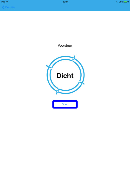

iOS App
Vandaag ben ik hard bezig geweest met de app. Na mijn besluit om mij te focussen op het puur nodige, heb ik een aantal stappen kunnen maken. Het ontwerp voor de app is verkleind, maar wel met een betere focus op de basis van mijn concept. Bovenstaande afbeeldingen zijn de app in werking op mijn iPad De communicatie tussen de app en de api/arduino is nu werkend en acties vanuit de app hebben effect op het deurslot!
Poster
Ook ben ik vandaag begonnen aan het ontwerpen van een poster voor mijn concept. De eerste schetsen heb ik met klasgenoten besproken en op basis daarvan ben ik verder gegaan. Hoe de poster er uiteindelijk uit zal zien zal ik posten tezamen met mijn reflectie op dit project.
Soms gaat er iets stuk...
Als laatste heb ik vandaag de transistor voor de solenoid moeten vervangen, die had helaas afgelopen weekend al het testen niet overleefd. Gelukkig hadden ze er genoeg bij de electro werkplaats.
1 note
·
View note
Text

Emergency Service LED Lights – warning flashing imagery!
List of components used:
UNO R3 Controller Board
830 Tie-Points Breadboard
Breadboard Jumper Wire (x4)
Resistor (x2)
Blue LED
Red LED
Technical Description:
Experimented with blinking LEDs on a breadboard, combined blue and red to create emergency service lights. Built upon the provided base code for the "Blink" and "RGB LED" examples provided by Arduino. Using multiple lights and alternating the light flow and delay by changing the parameter in the 'delay' command I created a blinking set of LED lights.
Code:
/*
Blink
Turns an LED on for one second, then off for one second, repeatedly.
Most Arduinos have an on-board LED you can control. On the UNO, MEGA and ZERO
it is attached to digital pin 13, on MKR1000 on pin 6. LED_BUILTIN is set to
the correct LED pin independent of which board is used.
If you want to know what pin the on-board LED is connected to on your Arduino
model, check the Technical Specs of your board at:
https://www.arduino.cc/en/Main/Products
modified 8 May 2014
by Scott Fitzgerald
modified 2 Sep 2016
by Arturo Guadalupi
modified 8 Sep 2016
by Colby Newman
This example code is in the public domain.
http://www.arduino.cc/en/Tutorial/Blink
*/
// the setup function runs once when you press reset or power the board
void setup() {
// initialize digital pin LED_BUILTIN as an output.
pinMode(12, OUTPUT);
pinMode(13, OUTPUT);
}
// the loop function runs over and over again forever
void loop() {
digitalWrite(12, HIGH);
digitalWrite(13, LOW); // turn the LED on (HIGH is the voltage level)
delay(100); // wait for a second
digitalWrite(12, LOW);
digitalWrite(13, HIGH); // turn the LED off by making the voltage LOW
delay(100); // wait for a second
}
1 note
·
View note
Text
Exploring Different Types of Arduino Kits for IoT and Education
Arduino is a famous open-source electronics platform that can be used to build everything from simple robotics to large IoT systems. Arduino kits are a terrific way to learn about electronics and programming while getting started with the platform. This blog post will look at three types of Arduino kits: the Arduino IoT Bundle, the Arduino Student Kit, and the Arduino MKR IoT Bundle.
The Arduino IoT Bundle is a collection of components and tools designed for building IoT projects. The kit includes an Arduino MKR1000 board, which is a powerful Wi-Fi-enabled microcontroller that can be used to connect to the internet and control sensors and other devices. A temperature and humidity sensor, a light sensor, and a servo motor are among the sensors and actuators included in the package. With the Arduino IoT Bundle, you can build projects that monitor environmental conditions, control home appliances, and even create your own smart home system.
The Arduino Student Kit is a comprehensive educational kit designed to introduce students to electronics and programming. The kit includes an Arduino UNO board, which is a popular microcontroller board used for a wide range of projects. It also includes a range of sensors and components, such as LEDs, resistors, and a breadboard, as well as a detailed guidebook that provides step-by-step instructions for building a variety of projects. With the Arduino Student Kit, students can learn the basics of electronics and programming, and gain hands-on experience building and testing their own projects.
The Arduino MKR IoT Bundle is a kit designed for building IoT projects using the powerful Arduino MKR1000 board. The kit comes with a number of sensors and actuators, such as a temperature and humidity sensor, a motion sensor, and a motor driver, as well as a thorough guidebook with step-by-step instructions for constructing a variety of IoT projects. With the Arduino MKR IoT Bundle, you can build projects that monitor environmental conditions, control home appliances, and even create your own smart home system. These kits are a great way to get started with electronics and programming and there are a variety of kits available to suit a wide range of interests and skill levels. Whether you want to construct IoT projects or learn about electronics and programming, there is an Arduino kit for you. The Arduino IoT Bundle, Arduino Student Kit, and Arduino MKR IoT Bundle are just a handful of the many kits available, each with its own combination of components and functionalities.
1 note
·
View note
Text
Hacking tools

GoodFET: this is an open-source JTAG adapter, based on the TI MSP430 FET UIF and EZ430U boards and is a USB interface.
The best starter antenna that you can use is ANT500. For you to use it, you will need an antenna since one is not provided by default.
HackRF One: the HackRF One is a software-defined radio that can transmit or receive radio signals from 1MHz to 6GHz.
You would need to connect it to any USB ports of the target computer and connect a LAN cable through to it. It can also be used to intercept traffic inbound to a target computer. It can be connected to the LAN and administered remotely.
LAN turtle: the USB LAN turtle works perfectly on Kali Linux.
The most interesting and amazing part of it all is that this device is incredibly cheap, costing only around $1.50. Just like the Arduino board above, this device can be programmed to function just like a USB rubber ducky.
DigiSpark: the DigiSpark is a low-powered microcontroller that can be programmed using the Arduino IDE found in Kali Linux.
You can also access its web server from a browser on Kali Linux. This can function better than the USB rubber ducky seen above. It is internet capable and you can use it as a human interface device like a USB mouse or keyboard, so it can perform like a USB rubber ducky.
Arduino MKR1000: you can program this device in Kali Linux, allowing it to perform various functions.
You can then operate this as a remote administration tool if you can have it installed in a network. These devices are cheap, readily available and can be hidden in places that cannot be easily discovered.
Raspberry pi: this is a small computer that you can install Kali Linux on and is quite small and portable.
This adapter is mostly preferred due to its packet injection capabilities and works well with most Kali Linux versions. It is supported by a huge number of Kali Linux kernels and uses the Atheros chipset that allows you to operate within all six Wi-Fi modes.
Alfa AWUS036NHA USB Wi-Fi adapter: the Alfa is the primary tool for attacking wireless networks using Kali Linux.
The captured traffic can be examined for sensitive content using software such as Wireshark in Kali Linux that we shall see in the next section. You can use it with Kali Linux to capture Wi-Fi traffic. You can operate it within the 2.4 GHz frequency and for Bluetooth traffic monitoring with Kali Linux.
UberTooth One: this is a very good tool for Bluetooth hacking.
These scripts can gather credentials from various locations, perform brute force attacks against password prompts, automatically copying files and directories to their internal memory. Since it is plug-and-play, it simulates a HUD device such as a keyboard and using scripts that you can write in Kali Linux, you can instruct it to run the scripts immediately when connected to the target USB device.
USB rubber ducky: the USB rubber ducky is a thumb drive-like device.
You can also collect credentials of connected victims by creating phishing pages and serving them to the unsuspecting victims, this is a much better way than relying on the Social Engineering Toolkit in Kali Linux.
Wi-Fi pineapple: the Wi-Fi pineapple is a device that allows you to clone and mimic existing Wi-Fi hotspots and create rogue access points that you can control.
You can use this device to test hardware and determine which ones are more resilient. This effectively disables any device that is not protected against such attacks. It works by taking in power from the connected device via USB, then multiplies it and discharges it into the data lines of the device.
USBKill: USBKill is a device that you can use to perform stress tests on hardware that is USB capable.
You can use these tools with your Kali Linux installation to modify the normal functionality of certain hardware devices that you have or can access. The following sections discuss some of the commonly used tools for hardware hacking. Hackers are therefore able to use tools together with Kali Linux to extract data and information out of such hardware in environments. Normally, these actions are not expected by the manufacturer of the hardware equipment. Hardware hacking enables hackers to be able to exploit the normal functionality of common hardware into their desires.
0 notes
Photo

Christmas sale: 50% Off. Learn about arduino hardware , arduino UNO & arduino MKR1000 Wifi board & electrical components such as motors & sensors. Click on the link below and enrol before the offer ends. https://www.edyusaurus.com/courses/robotics-arduino-hardware #arduino #arduinoproject #arduinouno #robotics #electronics #mechatronics #engineering #technology #onlinecourse #elearning (at Melbourne, Victoria, Australia) https://www.instagram.com/p/CXnDrAlJuWA/?utm_medium=tumblr
#arduino#arduinoproject#arduinouno#robotics#electronics#mechatronics#engineering#technology#onlinecourse#elearning
0 notes
Text
Using the MKR IoT Carrier Board as a game console
One of the first things many makers try to do when they receive a new piece of cool hardware is write a game for it. This is exactly what Johan Halmén did with his Breakout console that uses the Arduino MKR IoT Carrier board and an MKR1000 to both run and display the game.
Breakout typically involves moving a paddle horizontally along the bottom of the screen to bounce a ball that can destroy the bricks above it. However, since the carrier board’s color OLED screen is circular, Halmén had to create a different version of this, which he calls “BreakIn.” His game features a bunch of hexagonal tiles in the middle and a paddle that moves around the outside that is controlled by the onboard accelerometer. This lets the player tilt the device to move their paddle quickly and accurately.
Getting the circular display to work was a bit more of a challenge than a normal square one because coordinates had to be mapped using a bit of trigonometry first. Additionally, figuring out the angle of tilt and the collision geometry took some math as well. But once everything was up and working, the game was very fun to play, as can be seen in Halmén’s demo video below.
youtube
To read more about the code that went into this project, check out its Instructables write-up here.
The post Using the MKR IoT Carrier Board as a game console appeared first on Arduino Blog.
Using the MKR IoT Carrier Board as a game console was originally published on PlanetArduino
0 notes
Text
Beberapa Jenis Coding Arduino

1. Int (Integer) Integer adalah tipe data utama Anda untuk penyimpanan angka. Pada Arduino Uno (dan board berbasis ATmega lainnya) sebuah int menyimpan nilai 16-bit (2-byte). Ini menghasilkan kisaran -32.768 hingga 32.767 (nilai minimum -2 ^ 15 dan nilai maksimum (2 ^ 15) - 1). Pada papan berbasis Arduino Due dan SAMD (seperti MKR1000 dan Zero), sebuah int menyimpan nilai 32-bit (4-byte). Ini menghasilkan kisaran -2.147.483.648 hingga 2.147.483.647 (nilai minimum -2 ^ 31 dan nilai maksimum (2 ^ 31) - 1).
Contoh kode : int countUp = 0; // membuat integer variabel yang disebut 'countUp'' void setup() { Serial.begin(9600); // gunakan port serial untuk mencetak nomor } void loop() { countUp++; // Menambahkan 1 ke int countUp di setiap loop Serial.println(countUp); // mencetak status countUp saat ini delay(1000); //jeda selama satuan detik
}
2. Long (Long) Variabel panjang adalah variabel ukuran diperluas untuk penyimpanan angka, dan menyimpan 32 bit (4 byte), dari -2.147.483.648 hingga 2.147.483.647. Jika melakukan matematika dengan bilangan bulat, setidaknya salah satu angka harus diikuti oleh L, memaksanya menjadi panjang. Syntax : long var = val; Parameter : var : nama variabel val : nilai yang diberikan ke variabel Contoh kode : long speedOfLight = 186000L; ); digitalWrite(switchPin, HIGH); // nyalakan pullup resistor } void loop() { if (digitalRead(switchPin) == LOW) { // saklar ditekan – pullup menjaga pin tetap tinggi secara normal delay(100); // tunda ke saklar tolak running = !running; // toggle running variable digitalWrite(LEDpin, running); // menunjukan melalui LED } }
3. Float (Float) Tipe data untuk angka floating-point, angka yang memiliki titik desimal. Angka floating-point sering digunakan untuk memperkirakan nilai analog dan kontinu karena mereka memiliki resolusi lebih besar daripada bilangan bulat. Angka floating-point bisa sebesar 3.4028235E + 38 dan serendah -3.4028235E + 38 Mereka disimpan sebagai 32 bit (4 byte) informasi. Syntax : float var = val; Parameter : var : nama variabel val : nilai yang anda tetapkan untuk variabel itu Contoh program : float myfloat; float sensorCalbrate = 1.117; int x; int y; float z; x = 1; y = x / 2; // y mengandung 0, sekarang tidak dapat menyimpan pecahan z = (float)x / 2.0; // z sekarang berisi .5 (anda harus menggunakan 2.0 bukan 2) float x = 2.9; // variabel tipe float int y = x; // 2 Jika, sebaliknya, Anda ingin membulatkan selama proses konversi, Anda perlu menambahkan 0,5: float x = 2.9; int y = x + 0.5; // 3 atau gunakan fungsi round (): float x = 2.9; int y = round(x); // 3
Matematika floating point juga jauh lebih lambat daripada matematika integer dalam melakukan perhitungan, jadi harus dihindari jika, misalnya, loop harus dijalankan dengan kecepatan tinggi untuk fungsi timing kritis. Pemrogram sering berusaha keras untuk mengubah perhitungan floating point ke integer matematika untuk meningkatkan kecepatan.
0 notes
Text
Ejercicios con Arduino: BLINK
El código BLINK es uno de los ejemplos básicos que viene incluido en el programa de Arduino.
BLINK hace un loop de encendido y apagado de un LED en intervalos definidos en milisegundos.
Copio el código a continuación:
/* Blink
Turns an LED on for one second, then off for one second, repeatedly.
Most Arduinos have an on-board LED you can control. On the UNO, MEGA and ZERO it is attached to digital pin 13, on MKR1000 on pin 6. LED_BUILTIN is set to the correct LED pin independent of which board is used. If you want to know what pin the on-board LED is connected to on your Arduino model, check the Technical Specs of your board at: https://www.arduino.cc/en/Main/Products
modified 8 May 2014 by Scott Fitzgerald modified 2 Sep 2016 by Arturo Guadalupi modified 8 Sep 2016 by Colby Newman
This example code is in the public domain.
http://www.arduino.cc/en/Tutorial/Blink */
// the setup function runs once when you press reset or power the board void setup() { // initialize digital pin LED_BUILTIN as an output. pinMode(LED_BUILTIN, OUTPUT); }
// the loop function runs over and over again forever void loop() { digitalWrite(LED_BUILTIN, HIGH); // turn the LED on (HIGH is the voltage level) delay(1000); // wait for a second digitalWrite(LED_BUILTIN, LOW); // turn the LED off by making the voltage LOW delay(1000); // wait for a second }
El código propiamente tal, está en negrita, y los comentarios explicativos en cursiva.
En el video se explica en detalle el código, y se muestra su funcionamiento una vez cargado en la placa Arduino UNO, y conectado a la protoboard.
youtube
0 notes
Photo

Arduino MKRZero Is Like a Zero the Size of a MKR1000 ☞ https://blog.hackster.io/arduino-mkrzero-is-like-a-zero-the-size-of-a-mkr100-b01349d894ad #Arduino
3 notes
·
View notes
Photo

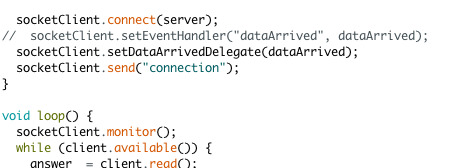

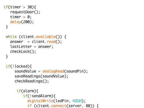
Arduino <> API
Gisteren hard bezig geweest met de laatste delen van mijn project. Gisteren heb ik de connectie tussen de API en arduino werkend gekregen. Het was even uitzoeken wat werkte overigens. Ik heb diverse socketlibraries voor arduino geprobeerd en op diverse manieren geprobeerd JSON te ontleden in arduino, echter geen van voorgenoemde manieren was een oplossing die werkte voor mijn volledige setup. De sockets wilde niet communiceren met mijn server, en de JSON library wilde niet samenwerken met de Wifi101 library nodig voor de MKR1000.
Arduino <> JSON?
In eerste instantie heb ik toen gekeken naar een andere manier om de JSON te ontleden echter heb ik er uiteindelijk voor gekozen om geen JSON meer als antwoord te sturen naar arduino toe. Ik stuur nu enkel een duidelijke code of de deur open moet of niet. Toen dit aan de praat was is het gelukt om in arduino het antwoord van de server te verwerken tot een bruikbare variabele.
0 notes
Text
Happy Holidays

Dear Valued Customer,
The sale you’ve been waiting for has come again!
The latest and improved version, TINA 12.1 has been released now with even more exciting features:
What’s new in TINA v12.1?
Schematic export to Altium and ORCAD (in TINA Industrial)
Google Cloud IOT interface
New Arduino model: MKR1000 support
Raspberry Pi 3 support (32 bit)
Ultrasonic Distance sensor
and more: https://www.tina.com/blog/happy-holydays/
0 notes
Text
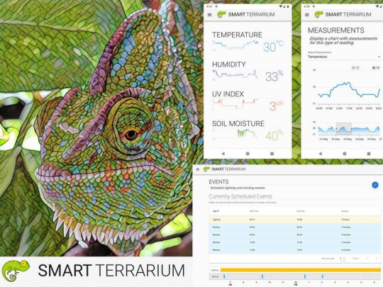
Smart Terrarium
Automated environment for reptiles to promote good husbandry and enable maximum lifespan for animals in captivity.

Things used in this project
Hardware components
Raspberry Pi 3 Model B×1
Arduino MKR1000 ×1
Arduino UNO & Genuino UNO ×1
DHT22 Temperature Sensor×1
Adafruit Waterproof DS18B20 Digital temperature sensor ×1
DFRobot Gravity: Analog UV Sensor (ML8511)×1
DFRobot Gravity: Analog Capacitive Soil Moisture Sensor- Corrosion Resistant×1
Ultrasonic Sensor - HC-SR04 (Generic) ×2Seeed Grove - 2-Channel SPDT Relay ×1
Hand tools and fabrication machines
3D Printer (generic)
Story
Intro
Smart Terrarium is the all in one system that provides the necessary information and automation to encourage a full and happy life for your reptiles. This system provides the user with the ability to monitor a variety of sensors in their animals habitat as well as control the lighting and misting system.
Backstory
This system was designed for my chameleon, Curie. She is a veiled chameleon and loves having her cage always kept in the optimal conditions. She is currently benefiting from the daily scheduled misting routines that the Smart Terrarium provides. This keeps her humidity in the appropriate range while also providing her with a nice place to cool off and get a drink.Another great part of having the Smart Terrarium is peace of mind. You no longer need to randomly check on the status of the mister bucket water level. You can always rely on the Smart Terrarium to notify you when you are running low. Also get notifications when the drain bucket is approaching maximum capacity.The most important part of this setup is the monitoring of the UV light. Chameleons require UV-B to produce Vitamin D. When a chameleon does not absorb enough calcium a chameleon can develop abnormalities in bone growth, rachitis, Metabolic Bone Disease (MBD) or just get very weak bones that are prone to breaking. The Smart Terrarium provides constant monitoring of UV light and can notify the user when the average UV index is below a certain threshold.
Hardware
This project uses a Raspberry Pi 3, an Arduino Uno, and a ArduinoMKR1000. The Raspberry Pi acts as our main system receiving readings from the Uno and MKR1000. The Pi also acts as a web server which delivers our app to the client when a user wants to monitor their system. They simply log in to a web page allowing them to interact with the Smart Terrarium from anywhere around the globe.

Raspberry Pi 3 A+
The MKR1000 is the main workhorse for getting sensor data and it sends its readings every second over wifi to the web server running on the Raspberry Pi. It has the following sensors connected to it:
(5) DS18B20 Digital Tempearture probes
(1) DHT22 Temperature & Humidity sensor
(1) UV sensor
(1)Soil Moisture sensor

Arduino MKR1000
The Arduino Uno is connected to the
Raspberry Pi via USB. It is used to monitor the water levels and also control the relays for the lights and misting pump. It has the following hardware connected:(2) HC-SR04 Ultrasonic Sensor
(2) Relays

Arduino Uno connected to 2 proximity sensors and 2 relays

Misting Bucket, Misting Pump, Drain Bucket with Proximity Sensor
Software
This system leverages the following open source software:Node.jsJohnny-fiveRethinkDBFirmataVue
Backend
The Raspberry Piis running an Express web server which collects readings from the sensors and saves them to a RethinkDB instance. The readings are being reported to the Pi every second so the user has access to the most current measurements.
The readings are saved every 5 minutes in Rethink DB for historical data.The Uno is running the PingFirmataSketch and using serial to expose the proximity sensors and relays to the Pi using Firmata protocol. The Pi leverages Johnny-five to allow the user to program in javascript.The MKR1000 is running a custom sketch using OneWire for the 5 temperature probes and then using analog inputs for the other sensors.
It posts the values to the Pi every second making sure the readings the user sees are fresh.
Frontend
The Raspberry Pi also serves up the front end portion of this app which leverages Vue.js. It allows the user to log in from anywhere having complete control over their pet's environment. The app works on any modern web browser so you can access it from a computer, tablet, or phone.The Smart Terrarium app allows the user to view the latests readings along with a sparkline graph of the previous day's historical data.The user can click through on any of the sensors
to view their history data.
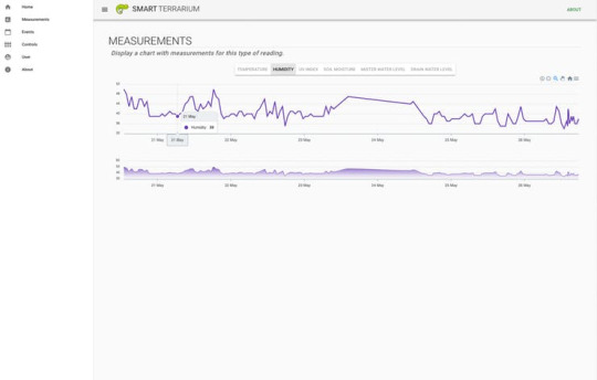
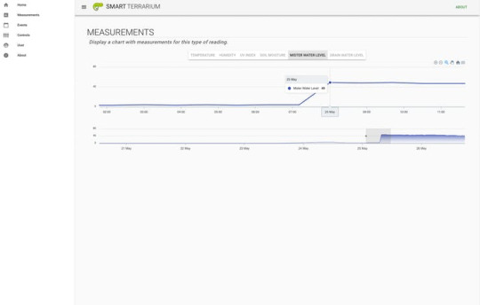
The Measurements page shows a graph with the entire sensor history. The user can select a section of the bottom graph to display a zoomed in version in the graph above. This allows the user to inspect the historic data for any spikes or dips where the environment is out of the norm.The user has the ability to schedule events including lighting and misting events.
The Event page displays the currently scheduled events and allows the user to add, edit, and delete events. These events are used to automate the lighting and misting sessions which provides peace making sure you never forget.
The Controls page allows the user to manually override the scheduled lighting and misting events. The page displays the current status of each relay and allows the user to toggle them with a click of a button.The Admin page allow the user to enter information about themselves for contact purposes. This is for the email notifications on high/low water levels on misting system as well as notifications for when the daily average UV index gets too low. There is also a spot for the animals birthday so we can provide birthday notifications.
Screenshots
Home Page

Home Page

Historical Measurements

Historical Measurements

Historical Measurements
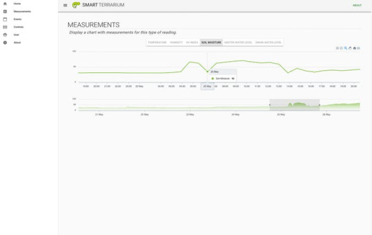
Historical Measurements (zoomed)>
Historical Measurements
Historical Measurements (zoomed)
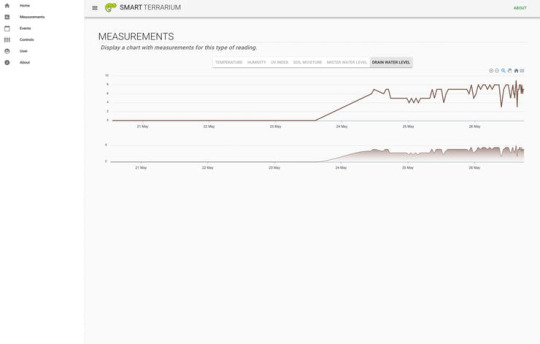
Historical Measurements
Events page for lighting and misting events.

Schedule Lighting and Misting Events
Controls page where the user can override the scheduled events.
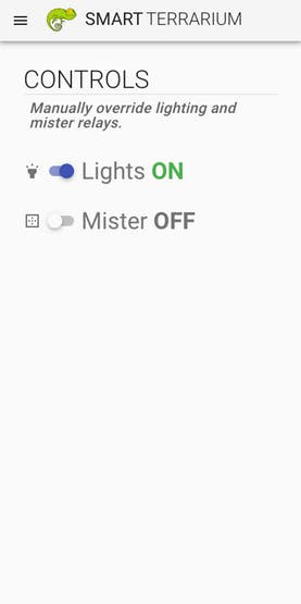
Misting and Lighting Overrides
Demo
Here is a demo of the overall system.
youtube
Demo of The Smart Terrarium
We hope you enjoyed our presentation of the Smart Terrarium and encourage any reptile owners to use this project to improve the lives of your pets.Thanks for your time and happy making!
Custom parts and enclosures
Plant Holder Brace
This provides extra support to the cage for hanging a plant.
Download Here
Mister Mount
This provides a nice clean installation of the misting head for the misting system.
Download Here
Schematics
Arduino Uno diagram
The Arduino Uno circuit used to control both relays for the lighting and misting system, as well as monitor the water levels on the misting bucket and drain.

Arduino MKR1000
This is really for the MKR1000 but tinkercad circuits didn't have it as a component. All pins are still correct.

Code
Ping Firmata
C#This is the version of firmata required for the
Proximity sensors
to function properly. Install this sketch on the Arduino Uno.
/* * Firmata is a generic protocol for communicating with microcontrollers * from software on a host computer. It is intended to work with * any host computer software package. * * To download a host software package, please clink on the following link * to open the download page in your default browser. * * http://firmata.org/wiki/Download */ /* Copyright (C) 2006-2008 Hans-Christoph Steiner. All rights reserved. Copyright (C) 2010-2011 Paul Stoffregen. All rights reserved. Copyright (C) 2009 Shigeru Kobayashi. All rights reserved. Copyright (C) 2009-2011 Jeff Hoefs. All rights reserved. Copyright (C) 2012 Julian Gaultier. All rights reserved. Copyright (C) 2015 Rick Waldron. All rights reserved. This library is free software; you can redistribute it and/or modify it under the terms of the GNU Lesser General Public License as published by the Free Software Foundation; either version 2.1 of the License, or (at your option) any later version. */ #include <Servo.h> #include <Wire.h> #include <Firmata.h> #define I2C_WRITE B00000000 #define I2C_READ B00001000 #define I2C_READ_CONTINUOUSLY B00010000 #define I2C_STOP_READING B00011000 #define I2C_READ_WRITE_MODE_MASK B00011000 #define I2C_10BIT_ADDRESS_MODE_MASK B00100000 #define MAX_QUERIES 8 #define MINIMUM_SAMPLING_INTERVAL 10 #define REGISTER_NOT_SPECIFIED -1 #define PING_READ 0x75 // PING_READ is for use with HCSR04 and similar "ultrasonic ping" components /*============================================================================== * GLOBAL VARIABLES *============================================================================*/ // analog inputs int analogInputsToReport = 0; // bitwise array to store pin reporting // digital input ports byte reportPINs[TOTAL_PORTS]; // 1 = report this port, 0 = silence byte previousPINs[TOTAL_PORTS]; // previous 8 bits sent // pins configuration byte pinConfig[TOTAL_PINS]; // configuration of every pin byte portConfigInputs[TOTAL_PORTS]; // each bit: 1 = pin in INPUT, 0 = anything else int pinState[TOTAL_PINS]; // any value that has been written // timer variables unsigned long currentMillis; // store the current value from millis() unsigned long previousMillis; // for comparison with currentMillis int samplingInterval = 19; // how often to run the main loop (in ms) // i2c data struct i2c_device_info { byte addr; byte reg; byte bytes; }; // for i2c read continuous more i2c_device_info query[MAX_QUERIES]; byte i2cRxData[32]; boolean isI2CEnabled = false; signed char queryIndex = -1; // default delay time between i2c read request and Wire.requestFrom() unsigned int i2cReadDelayTime = 0; Servo servos[MAX_SERVOS]; /*============================================================================== * FUNCTIONS *============================================================================*/ void readAndReportData(byte address, int theRegister, byte numBytes) { // allow I2C requests that don't require a register read // for example, some devices using an interrupt pin to signify new data available // do not always require the register read so upon interrupt you call Wire.requestFrom() if (theRegister != REGISTER_NOT_SPECIFIED) { Wire.beginTransmission(address); Wire.write((byte)theRegister); Wire.endTransmission(); delayMicroseconds(i2cReadDelayTime); // delay is necessary for some devices such as WiiNunchuck } else { theRegister = 0; // fill the register with a dummy value } Wire.requestFrom(address, numBytes); // all bytes are returned in requestFrom // check to be sure correct number of bytes were returned by slave if (numBytes == Wire.available()) { i2cRxData[0] = address; i2cRxData[1] = theRegister; for (int i = 0; i < numBytes; i++) { i2cRxData[2 + i] = Wire.read(); } } else { if (numBytes > Wire.available()) { Firmata.sendString("I2C Read Error: Too many bytes received"); } else { Firmata.sendString("I2C Read Error: Too few bytes received"); } } // send slave address, register and received bytes Firmata.sendSysex(SYSEX_I2C_REPLY, numBytes + 2, i2cRxData); } void outputPort(byte portNumber, byte portValue, byte forceSend) { // pins not configured as INPUT are cleared to zeros portValue = portValue & portConfigInputs[portNumber]; // only send if the value is different than previously sent if (forceSend || previousPINs[portNumber] != portValue) { Firmata.sendDigitalPort(portNumber, portValue); previousPINs[portNumber] = portValue; } } /* ----------------------------------------------------------------------------- * check all the active digital inputs for change of state, then add any events * to the Serial output queue using Serial.print() */ void checkDigitalInputs(void) { /* Using non-looping code allows constants to be given to readPort(). * The compiler will apply substantial optimizations if the inputs * to readPort() are compile-time constants. */ if (TOTAL_PORTS > 0 && reportPINs[0]) outputPort(0, readPort(0, portConfigInputs[0]), false); if (TOTAL_PORTS > 1 && reportPINs[1]) outputPort(1, readPort(1, portConfigInputs[1]), false); if (TOTAL_PORTS > 2 && reportPINs[2]) outputPort(2, readPort(2, portConfigInputs[2]), false); if (TOTAL_PORTS > 3 && reportPINs[3]) outputPort(3, readPort(3, portConfigInputs[3]), false); if (TOTAL_PORTS > 4 && reportPINs[4]) outputPort(4, readPort(4, portConfigInputs[4]), false); if (TOTAL_PORTS > 5 && reportPINs[5]) outputPort(5, readPort(5, portConfigInputs[5]), false); if (TOTAL_PORTS > 6 && reportPINs[6]) outputPort(6, readPort(6, portConfigInputs[6]), false); if (TOTAL_PORTS > 7 && reportPINs[7]) outputPort(7, readPort(7, portConfigInputs[7]), false); if (TOTAL_PORTS > 8 && reportPINs[8]) outputPort(8, readPort(8, portConfigInputs[8]), false); if (TOTAL_PORTS > 9 && reportPINs[9]) outputPort(9, readPort(9, portConfigInputs[9]), false); if (TOTAL_PORTS > 10 && reportPINs[10]) outputPort(10, readPort(10, portConfigInputs[10]), false); if (TOTAL_PORTS > 11 && reportPINs[11]) outputPort(11, readPort(11, portConfigInputs[11]), false); if (TOTAL_PORTS > 12 && reportPINs[12]) outputPort(12, readPort(12, portConfigInputs[12]), false); if (TOTAL_PORTS > 13 && reportPINs[13]) outputPort(13, readPort(13, portConfigInputs[13]), false); if (TOTAL_PORTS > 14 && reportPINs[14]) outputPort(14, readPort(14, portConfigInputs[14]), false); if (TOTAL_PORTS > 15 && reportPINs[15]) outputPort(15, readPort(15, portConfigInputs[15]), false); } // ----------------------------------------------------------------------------- /* sets the pin mode to the correct state and sets the relevant bits in the * two bit-arrays that track Digital I/O and PWM status */ void setPinModeCallback(byte pin, int mode) { if (pinConfig[pin] == I2C && isI2CEnabled && mode != I2C) { // disable i2c so pins can be used for other functions // the following if statements should reconfigure the pins properly disableI2CPins(); } if (IS_PIN_SERVO(pin) && mode != SERVO && servos[PIN_TO_SERVO(pin)].attached()) { servos[PIN_TO_SERVO(pin)].detach(); } if (IS_PIN_ANALOG(pin)) { reportAnalogCallback(PIN_TO_ANALOG(pin), mode == ANALOG ? 1 : 0); // turn on/off reporting } if (IS_PIN_DIGITAL(pin)) { if (mode == INPUT) { portConfigInputs[pin / 8] |= (1 << (pin & 7)); } else { portConfigInputs[pin / 8] &= ~(1 << (pin & 7)); } } pinState[pin] = 0; switch (mode) { case ANALOG: if (IS_PIN_ANALOG(pin)) { if (IS_PIN_DIGITAL(pin)) { pinMode(PIN_TO_DIGITAL(pin), INPUT); // disable output driver digitalWrite(PIN_TO_DIGITAL(pin), LOW); // disable internal pull-ups } pinConfig[pin] = ANALOG; } break; case INPUT: if (IS_PIN_DIGITAL(pin)) { pinMode(PIN_TO_DIGITAL(pin), INPUT); // disable output driver digitalWrite(PIN_TO_DIGITAL(pin), LOW); // disable internal pull-ups pinConfig[pin] = INPUT; } break; case OUTPUT: if (IS_PIN_DIGITAL(pin)) { digitalWrite(PIN_TO_DIGITAL(pin), LOW); // disable PWM pinMode(PIN_TO_DIGITAL(pin), OUTPUT); pinConfig[pin] = OUTPUT; } break; case PWM: if (IS_PIN_PWM(pin)) { pinMode(PIN_TO_PWM(pin), OUTPUT); analogWrite(PIN_TO_PWM(pin), 0); pinConfig[pin] = PWM; } break; case SERVO: if (IS_PIN_SERVO(pin)) { pinConfig[pin] = SERVO; if (!servos[PIN_TO_SERVO(pin)].attached()) { servos[PIN_TO_SERVO(pin)].attach(PIN_TO_DIGITAL(pin)); } } break; case I2C: if (IS_PIN_I2C(pin)) { // mark the pin as i2c �� // the user must call I2C_CONFIG to enable I2C for a device pinConfig[pin] = I2C; } break; default: Firmata.sendString("Unknown pin mode"); // TODO: put error msgs in EEPROM } // TODO: save status to EEPROM here, if changed } void analogWriteCallback(byte pin, int value) { if (pin < TOTAL_PINS) { switch (pinConfig[pin]) { case SERVO: if (IS_PIN_SERVO(pin)) servos[PIN_TO_SERVO(pin)].write(value); pinState[pin] = value; break; case PWM: if (IS_PIN_PWM(pin)) analogWrite(PIN_TO_PWM(pin), value); pinState[pin] = value; break; } } } void digitalWriteCallback(byte port, int value) { byte pin, lastPin, mask = 1, pinWriteMask = 0; if (port < TOTAL_PORTS) { // create a mask of the pins on this port that are writable. lastPin = port * 8 + 8; if (lastPin > TOTAL_PINS) lastPin = TOTAL_PINS; for (pin = port * 8; pin < lastPin; pin++) { // do not disturb non-digital pins (eg, Rx & Tx) if (IS_PIN_DIGITAL(pin)) { // only write to OUTPUT and INPUT (enables pullup) // do not touch pins in PWM, ANALOG, SERVO or other modes if (pinConfig[pin] == OUTPUT || pinConfig[pin] == INPUT) { pinWriteMask |= mask; pinState[pin] = ((byte)value & mask) ? 1 : 0; } } mask = mask << 1; } writePort(port, (byte)value, pinWriteMask); } } // ----------------------------------------------------------------------------- /* sets bits in a bit array (int) to toggle the reporting of the analogIns */ //void FirmataClass::setAnalogPinReporting(byte pin, byte state) { //} void reportAnalogCallback(byte analogPin, int value) { if (analogPin < TOTAL_ANALOG_PINS) { if (value == 0) { analogInputsToReport = analogInputsToReport & ~(1 << analogPin); } else { analogInputsToReport = analogInputsToReport | (1 << analogPin); } } // TODO: save status to EEPROM here, if changed } void reportDigitalCallback(byte port, int value) { if (port < TOTAL_PORTS) { reportPINs[port] = (byte)value; } // do not disable analog reporting on these 8 pins, to allow some // pins used for digital, others analog. Instead, allow both types // of reporting to be enabled, but check if the pin is configured // as analog when sampling the analog inputs. Likewise, while // scanning digital pins, portConfigInputs will mask off values from any // pins configured as analog } /*============================================================================== * SYSEX-BASED commands *============================================================================*/ void sysexCallback(byte command, byte argc, byte *argv) { byte mode; byte slaveAddress; byte slaveRegister; byte data; unsigned int delayTime; switch (command) { case I2C_REQUEST: mode = argv[1] & I2C_READ_WRITE_MODE_MASK; if (argv[1] & I2C_10BIT_ADDRESS_MODE_MASK) { Firmata.sendString("10-bit addressing not supported"); return; } else { slaveAddress = argv[0]; } switch (mode) { case I2C_WRITE: Wire.beginTransmission(slaveAddress); for (byte i = 2; i < argc; i += 2) { data = argv[i] + (argv[i + 1] << 7); Wire.write((byte)data); } Wire.endTransmission(); delayMicroseconds(70); break; case I2C_READ: case I2C_READ_CONTINUOUSLY: if (argc == 6) { // a slave register is specified slaveRegister = argv[2] + (argv[3] << 7); data = argv[4] + (argv[5] << 7); // bytes to read } else { // a slave register is NOT specified slaveRegister = (int)REGISTER_NOT_SPECIFIED; data = argv[2] + (argv[3] << 7); // bytes to read } if (mode == I2C_READ) { readAndReportData(slaveAddress, slaveRegister, data); } else { if ((queryIndex + 1) >= MAX_QUERIES) { Firmata.sendString("too many queries"); break; } queryIndex++; query[queryIndex].addr = slaveAddress; query[queryIndex].reg = slaveRegister; query[queryIndex].bytes = data; } break; case I2C_STOP_READING: byte queryIndexToSkip; // if read continuous mode is enabled for only 1 i2c device, disable // read continuous reporting for that device if (queryIndex <= 0) { queryIndex = -1; } else { // if read continuous mode is enabled for multiple devices, // determine which device to stop reading and remove it's data from // the array, shifiting other array data to fill the space for (byte i = 0; i < queryIndex + 1; i++) { if (query[i].addr == slaveAddress) { queryIndexToSkip = i; break; } } for (byte i = queryIndexToSkip; i < queryIndex + 1; i++) { if (i < MAX_QUERIES) { query[i].addr = query[i + 1].addr; query[i].reg = query[i + 1].reg; query[i].bytes = query[i + 1].bytes; } } queryIndex--; } break; default: break; } break; case I2C_CONFIG: delayTime = (argv[0] + (argv[1] << 7)); if (delayTime > 0) { i2cReadDelayTime = delayTime; } if (!isI2CEnabled) { enableI2CPins(); } break; case SERVO_CONFIG: if (argc > 4) { // these vars are here for clarity, they'll optimized away by the compiler byte pin = argv[0]; int minPulse = argv[1] + (argv[2] << 7); int maxPulse = argv[3] + (argv[4] << 7); if (IS_PIN_SERVO(pin)) { if (servos[PIN_TO_SERVO(pin)].attached()) { servos[PIN_TO_SERVO(pin)].detach(); } servos[PIN_TO_SERVO(pin)].attach(PIN_TO_DIGITAL(pin), minPulse, maxPulse); setPinModeCallback(pin, SERVO); } } break; case SAMPLING_INTERVAL: if (argc > 1) { samplingInterval = argv[0] + (argv[1] << 7); if (samplingInterval < MINIMUM_SAMPLING_INTERVAL) { samplingInterval = MINIMUM_SAMPLING_INTERVAL; } } else { //Firmata.sendString("Not enough data"); } break; case EXTENDED_ANALOG: if (argc > 1) { int val = argv[1]; if (argc > 2) { val |= (argv[2] << 7); } if (argc > 3) { val |= (argv[3] << 14); } analogWriteCallback(argv[0], val); } break; case CAPABILITY_QUERY: Serial.write(START_SYSEX); Serial.write(CAPABILITY_RESPONSE); for (byte pin = 0; pin < TOTAL_PINS; pin++) { if (IS_PIN_DIGITAL(pin)) { Serial.write((byte)INPUT); Serial.write(1); Serial.write((byte)OUTPUT); Serial.write(1); Serial.write((byte)PING_READ); Serial.write(1); } if (IS_PIN_ANALOG(pin)) { Serial.write(ANALOG); Serial.write(10); } if (IS_PIN_PWM(pin)) { Serial.write(PWM); Serial.write(8); } if (IS_PIN_SERVO(pin)) { Serial.write(SERVO); Serial.write(14); } if (IS_PIN_I2C(pin)) { Serial.write(I2C); Serial.write(1); // to do: determine appropriate value } Serial.write(127); } Serial.write(END_SYSEX); break; case PIN_STATE_QUERY: if (argc > 0) { byte pin = argv[0]; Serial.write(START_SYSEX); Serial.write(PIN_STATE_RESPONSE); Serial.write(pin); if (pin < TOTAL_PINS) { Serial.write((byte)pinConfig[pin]); Serial.write((byte)pinState[pin] & 0x7F); if (pinState[pin] & 0xFF80) { Serial.write((byte)(pinState[pin] >> 7) & 0x7F); } if (pinState[pin] & 0xC000) { Serial.write((byte)(pinState[pin] >> 14) & 0x7F); } } Serial.write(END_SYSEX); } break; case ANALOG_MAPPING_QUERY: Serial.write(START_SYSEX); Serial.write(ANALOG_MAPPING_RESPONSE); for (byte pin = 0; pin < TOTAL_PINS; pin++) { Serial.write(IS_PIN_ANALOG(pin) ? PIN_TO_ANALOG(pin) : 127); } Serial.write(END_SYSEX); break; case PING_READ: { byte pulseDurationArray[4] = { (argv[2] & 0x7F) | ((argv[3] & 0x7F) << 7), (argv[4] & 0x7F) | ((argv[5] & 0x7F) << 7), (argv[6] & 0x7F) | ((argv[7] & 0x7F) << 7), (argv[8] & 0x7F) | ((argv[9] & 0x7F) << 7)}; unsigned long pulseDuration = ((unsigned long)pulseDurationArray[0] << 24) + ((unsigned long)pulseDurationArray[1] << 16) + ((unsigned long)pulseDurationArray[2] << 8) + ((unsigned long)pulseDurationArray[3]); if (argv[1] == HIGH) { pinMode(argv[0], OUTPUT); digitalWrite(argv[0], LOW); delayMicroseconds(2); digitalWrite(argv[0], HIGH); delayMicroseconds(pulseDuration); digitalWrite(argv[0], LOW); } else { digitalWrite(argv[0], HIGH); delayMicroseconds(2); digitalWrite(argv[0], LOW); delayMicroseconds(pulseDuration); digitalWrite(argv[0], HIGH); } unsigned long duration; byte responseArray[5]; byte timeoutArray[4] = { (argv[10] & 0x7F) | ((argv[11] & 0x7F) << 7), (argv[12] & 0x7F) | ((argv[13] & 0x7F) << 7), (argv[14] & 0x7F) | ((argv[15] & 0x7F) << 7), (argv[16] & 0x7F) | ((argv[17] & 0x7F) << 7)}; unsigned long timeout = ((unsigned long)timeoutArray[0] << 24) + ((unsigned long)timeoutArray[1] << 16) + ((unsigned long)timeoutArray[2] << 8) + ((unsigned long)timeoutArray[3]); pinMode(argv[0], INPUT); duration = pulseIn(argv[0], argv[1], timeout); responseArray[0] = argv[0]; responseArray[1] = (((unsigned long)duration >> 24) & 0xFF); responseArray[2] = (((unsigned long)duration >> 16) & 0xFF); responseArray[3] = (((unsigned long)duration >> 8) & 0xFF); responseArray[4] = (((unsigned long)duration & 0xFF)); Firmata.sendSysex(PING_READ, 5, responseArray); break; } } } void enableI2CPins() { for (byte i = 0; i < TOTAL_PINS; i++) { if (IS_PIN_I2C(i)) { // mark pins as i2c so they are ignore in non i2c data requests setPinModeCallback(i, I2C); } } isI2CEnabled = true; // is there enough time before the first I2C request to call this here? Wire.begin(); } void disableI2CPins() { isI2CEnabled = false; queryIndex = -1; } void systemResetCallback() { if (isI2CEnabled) { disableI2CPins(); } for (byte i = 0; i < TOTAL_PORTS; i++) { reportPINs[i] = false; // by default, reporting off portConfigInputs[i] = 0; // until activated previousPINs[i] = 0; } // pins with analog capability default to analog input // otherwise, pins default to digital output for (byte i = 0; i < TOTAL_PINS; i++) { if (IS_PIN_ANALOG(i)) { // turns off pullup, configures everything setPinModeCallback(i, ANALOG); } else { // sets the output to 0, configures portConfigInputs setPinModeCallback(i, OUTPUT); } } // by default, do not report any analog inputs analogInputsToReport = 0; } void setup() { Firmata.setFirmwareVersion(FIRMATA_MAJOR_VERSION, FIRMATA_MINOR_VERSION); Firmata.attach(ANALOG_MESSAGE, analogWriteCallback); Firmata.attach(DIGITAL_MESSAGE, digitalWriteCallback); Firmata.attach(REPORT_ANALOG, reportAnalogCallback); Firmata.attach(REPORT_DIGITAL, reportDigitalCallback); Firmata.attach(SET_PIN_MODE, setPinModeCallback); Firmata.attach(START_SYSEX, sysexCallback); Firmata.attach(SYSTEM_RESET, systemResetCallback); Firmata.begin(57600); systemResetCallback(); // reset to default config } void loop() { byte pin, analogPin; /* DIGITALREAD - as fast as possible, check for changes and output them to the * FTDI buffer using Serial.print() */ checkDigitalInputs(); /* SERIALREAD - processing incoming messagse as soon as possible, while still * checking digital inputs. */ while (Firmata.available()) { Firmata.processInput(); } /* SEND FTDI WRITE BUFFER - make sure that the FTDI buffer doesn't go over * 60 bytes. use a timer to sending an event character every 4 ms to * trigger the buffer to dump. */ currentMillis = millis(); if (currentMillis - previousMillis > samplingInterval) { previousMillis += samplingInterval; /* ANALOGREAD - do all analogReads() at the configured sampling interval */ for (pin = 0; pin < TOTAL_PINS; pin++) { if (IS_PIN_ANALOG(pin) && pinConfig[pin] == ANALOG) { analogPin = PIN_TO_ANALOG(pin); if (analogInputsToReport & (1 << analogPin)) { Firmata.sendAnalog(analogPin, analogRead(analogPin)); } } } // report i2c data for all device with read continuous mode enabled if (queryIndex > -1) { for (byte i = 0; i < queryIndex + 1; i++) { readAndReportData(query[i].addr, query[i].reg, query[i].bytes); } } } }
MKR1000 Sketch
C#This sketch sends the majority of sensor readings to the app running on the Raspberry Pi. Make sure to update the Wifi SSID and Password before uploading.
#include <OneWire.h> #include <DallasTemperature.h> #include <ArduinoHttpClient.h> #include <WiFi101.h> #include <SimpleDHT.h> // Using Pin 5 of MKR1000 #define ONE_WIRE_BUS_PIN 5 // TODO: Move out ot separate file #define SECRET_SSID "SECRET_SSID" #define SECRET_PASS "SECRET_PASS" #define RIG_NAME "Gill" char ssid[] = SECRET_SSID; char pass[] = SECRET_PASS; // Setup a oneWire instance for temperature probes OneWire oneWire(ONE_WIRE_BUS_PIN); // Pass our oneWire reference to Dallas Temperature. DallasTemperature sensors(&oneWire); // probe_a: "28 FF 2F 9C B0 16 3 34" // probe_b: "28 FF 36 1E B1 16 4 4D" // probe_c: "28 FF 27 1E B1 16 4 FC" // probe_d: "28 FF 6A 74 B0 16 5 87" // probe_e: "28 FF E B5 B0 16 3 E2" // Define device addresses for each probe DeviceAddress Probe01 = {0x28, 0xFF, 0x2F, 0x9C, 0xB0, 0x16, 0x03, 0x34}; DeviceAddress Probe02 = {0x28, 0xFF, 0x36, 0x1E, 0xB1, 0x16, 0x04, 0x4D}; DeviceAddress Probe03 = {0x28, 0xFF, 0x27, 0x1E, 0xB1, 0x16, 0x04, 0xFC}; DeviceAddress Probe04 = {0x28, 0xFF, 0x6A, 0x74, 0xB0, 0x16, 0x05, 0x87}; DeviceAddress Probe05 = {0x28, 0xFF, 0x0E, 0xB5, 0xB0, 0x16, 0x03, 0xE2}; int uvSensor = A1; int uvIndex = 0; int pinDHT22 = A2; SimpleDHT22 dht22(pinDHT22); int soilSensor = A3; int soilMoisture = 0; char serverAddress[] = "192.168.86.127"; // raspberry pi address int port = 3030; WiFiClient wifi; HttpClient client = HttpClient(wifi, serverAddress, port); int status = WL_IDLE_STATUS; String response; int statusCode = 0; void setup() { // start serial port to show results Serial.begin(9600); delay(3000); pinMode(LED_BUILTIN, OUTPUT); while (status != WL_CONNECTED) { Serial.print("Attempting to connect to Network named: "); Serial.println(ssid); // print the network name (SSID); // Connect to WPA/WPA2 network: status = WiFi.begin(ssid, pass); } // print the SSID of the network you're attached to: Serial.print("SSID: "); Serial.println(WiFi.SSID()); // print your WiFi shield's IP address: IPAddress ip = WiFi.localIP(); Serial.print("IP Address: "); Serial.println(ip); Serial.print("Initializing Temperature Control Library Version "); Serial.println(DALLASTEMPLIBVERSION); // Initialize the Temperature measurement library sensors.begin(); // set the resolution to 10 bit (Can be 9 to 12 bits .. lower is faster) sensors.setResolution(Probe01, 9); sensors.setResolution(Probe02, 9); sensors.setResolution(Probe03, 9); sensors.setResolution(Probe04, 9); sensors.setResolution(Probe05, 9); } void loop() /****** LOOP: RUNS CONSTANTLY ******/ { Serial.println(); Serial.print("Total Probes: "); Serial.println(sensors.getDeviceCount()); // Command all devices on bus to read temperature sensors.requestTemperatures(); float probeA = sensors.getTempC(Probe01); float probeB = sensors.getTempC(Probe02); float probeC = sensors.getTempC(Probe03); float probeD = sensors.getTempC(Probe04); float probeE = sensors.getTempC(Probe05); float moistureSensorValue = analogRead(soilSensor); soilMoisture = ((moistureSensorValue / 1024) - 1) * 100 * -1; float uvSensorValue = analogRead(uvSensor); uvIndex = uvSensorValue / 1024 * 3.3 / 0.1; Serial.print("Rig Name: "); Serial.println(String(RIG_NAME)); Serial.print("ProbeA: "); printTemperature(Probe01); Serial.println(); Serial.print("ProbeB: "); printTemperature(Probe02); Serial.println(); Serial.print("ProbeC: "); printTemperature(Probe03); Serial.println(); Serial.print("ProbeD: "); printTemperature(Probe04); Serial.println(); Serial.print("ProbeE: "); printTemperature(Probe05); Serial.println(); Serial.print("soilMoisture: "); Serial.print(soilMoisture); Serial.println(); Serial.print("uvIndex: "); Serial.print(uvIndex); Serial.println(); byte temperature = 0; byte humidity = 0; int err = SimpleDHTErrSuccess; if ((err = dht22.read(&temperature, &humidity, NULL)) != SimpleDHTErrSuccess) { Serial.print("Read DHT22 failed, err="); Serial.println(err); } else { Serial.print("DHT22: "); Serial.print((int)temperature); Serial.print(" *C, "); Serial.print((int)humidity); Serial.println(" RH%"); } String postURL = String("POST readings to " + String(serverAddress) + ':' + String(port)); Serial.println(postURL); String contentType = "application/x-www-form-urlencoded"; String postData = String( "probeA=" + String(probeA) + "&probeB=" + String(probeB) + "&probeC=" + String(probeC) + "&probeD=" + String(probeD) + "&probeE=" + String(probeE) + "&rig_name=" + String(RIG_NAME) + "&uvIndex=" + String(uvIndex) + "&soilMoisture=" + String(soilMoisture) + "&humidity=" + String(humidity) + "&temperature=" + String(temperature)); digitalWrite(LED_BUILTIN, HIGH); client.post("/temperatures", contentType, postData); // read the status code and body of the response statusCode = client.responseStatusCode(); response = client.responseBody(); Serial.print("Status code: "); Serial.println(statusCode); Serial.print("Response: "); Serial.println(response); digitalWrite(LED_BUILTIN, LOW); delay(100); digitalWrite(LED_BUILTIN, HIGH); delay(100); digitalWrite(LED_BUILTIN, LOW); delay(100); digitalWrite(LED_BUILTIN, HIGH); delay(100); digitalWrite(LED_BUILTIN, LOW); delay(1000); } // print temperature for device adress void printTemperature(DeviceAddress deviceAddress) { float tempC = sensors.getTempC(deviceAddress); if (tempC == -127.00) { Serial.print("Error getting temperature "); } else { Serial.print(tempC, 1); Serial.print(" C"); // Serial.print(" F: "); // Serial.print(DallasTemperature::toFahrenheit(tempC)); } }
SmartTerrariumClient
This is the Client portion of Smart Terrarium built using Vue.js.
ryanjgill / smart-terrarium-client
Client for Smart Terrarium —
Read More
Latest commit to the master branch on 5-27-2019
Download as zip
SmartTerrariumApp
Smart Terrarium App for receiving data, controlling hardware, and running the Smart Terrarium Client. This repo also contains the sketch for the MKR1000.
ryanjgill / smart-terrarium-app
Smart Terrarium App for receiving data, controlling hardware, and running the Smart Terrarium Client — Read More
Latest commit to the master branch on 5-31-2019
Download as zip
(This article copied from hackster.io Author: Ryan Gill)
0 notes
Text
Assignment 4: what is the difference between the variable types: ‘int’ and 'long’ in Arduino language? Write the answer in your blog
Integers according to Arduino:
“Integers are your primary data-type for number storage.
On the Arduino Uno (and other ATmega based boards) an int stores a 16-bit (2-byte) value. This yields a range of -32,768 to 32,767 (minimum value of -2^15 and a maximum value of (2^15) - 1). On the Arduino Due and SAMD based boards (like MKR1000 and Zero), an int stores a 32-bit (4-byte) value. This yields a range of -2,147,483,648 to 2,147,483,647 (minimum value of -2^31 and a maximum value of (2^31) - 1).
int’s store negative numbers with a technique called (2’s complement math). The highest bit, sometimes referred to as the "sign" bit, flags the number as a negative number. The rest of the bits are inverted and 1 is added.
The Arduino takes care of dealing with negative numbers for you, so that arithmetic operations work transparently in the expected manner. There can be an unexpected complication in dealing with the bitshift right operator (>>) however.” Long according to Arduino: “Long variables are extended size variables for number storage, and store 32 bits (4 bytes), from -2,147,483,648 to 2,147,483,647.If doing math with integers, at least one of the numbers must be followed by an L, forcing it to be a long. See the Integer Constants page for details.” So Long can store 32 bits ( 4 bytes ) and Int can store 16 bits ( 2 bytes ).
0 notes
Photo

Christmas sale: 50% Off. Don’t pay A$199.98 instead just pay A$99.99. Learn about arduino hardware , arduino UNO & arduino MKR1000 Wifi board & electrical components such as motors & sensors. Click on the link below and enrol before the offer ends. https://www.edyusaurus.com/courses/robotics-arduino-hardware #arduino #arduinoproject #arduinouno #robotics #electronics #mechatronics #engineering #technology #onlinecourse #elearning https://www.instagram.com/p/CXfrHc8JnJp/?utm_medium=tumblr
#arduino#arduinoproject#arduinouno#robotics#electronics#mechatronics#engineering#technology#onlinecourse#elearning
0 notes