#assembler directives (debug
Explore tagged Tumblr posts
Visit Tumblr Blog
Explore Tumblr blogs with no restrictions, modern design and the best experience.
Last Seen Tumblr Blogs


Fun Fact
There were a total of 171.5 billion posts on Tumblr in 2019.
Note
How would one go about learning how to make something like the cactus?
Like prerequisites, older code, hardware stuff, etc.
The main prerequisites I can think of are being heavily interested in vintage computers, and having the drive to try and fail and then try again.
I started with building Grant Searle's design, borrowing from other working designs as I went. However, for the front panel? That's alot of time designing, learning, simulating in Logisim, and testing with physical logic gates to produce something 100% original and of my own design. I imagine most folks won't want to go to the trouble of designing an entire front panel state machine like I did.
The good news is that there are way more kits that can help teach the necessary skills than ever before! Most notably, Ben Eater's 6502 kit is a really great way to learn many of the things that I've put into practice here. He has a whole youtube video series associated with it, walking through concepts, construction, programming, etc. step by step. Even if you don't build one of his kits, watching them is an informative process. *I* learned alot, even after having built the Cactus.
If you're going the Z80 direction, the RC2014 series of kits can teach you plenty. There's also glitchworks kits in a few processor types, but those tend to be a bit more for the advanced user. There's the 1802 Membership Card but that's small and not really expandable. I could be here all day listing kits that can help teach and build up experience.
I should mention that I have a computer science degree in my back pocket, but learning logic gates or using assembly was only lightly touched on in the course of my studies. Most of the programming I do involved messing around in BASIC anyway.
I really didn't have a game plan for some of it, so alot of my learning process was trial and error. Alot of errors, in fact. Still making them, and learning from them. I also took the harder route to construction, since I didn't know how to use EDA tools for designing PCBs like KiCAD or Altium or Eagle (don't use Fritzing for the love of fuck).
Oh, one other thing I can recommend: reading through contemporary 1970s computing magazines like Byte (check the internet archive for back issues). There are all sorts of cool projects and ideas present that can really guide you. It doesn't hurt to have a copy of Don Lancaster's TTL Cookbook on hand (I think it's in PDF form online).
Finding a community to help you out is also a great idea. Even back in the 1970s, many folks who jump-started the home computer revolution had the Homebrew Computer Club to help them out. Community meetings to bounce ideas off of, and help one another through debugging are essential in my book -- you don't have to work in a vacuum. I've got a few places I've asked for help, most notably the Retrotech Crew discord server. I've had the benefit of friends who also have homebrewed designs like @techav, who have inspired me with their ideas, but helped me out with mine. In turn, as I've learned, I've been able to help out others.
Hopefully that answers your question. Keep 'em coming!
44 notes
·
View notes
Text
I thinks it's easy to do in any engine.
My hypothesis is that these large studios have developers and designers in different team with poor communication. So, what happens is that the developers receive some large list of things to implement and then the designers get them and put them in the game world.
But design changes over time and when designers are like "wait, now for the rest we decided to use bonefires instead of talking to an npc" (I don't know if that was the story behind the design in the case of fromsoft games, I just use this as an example of possible explanation). So what they do is that, instead of just saying to the devs "hey we need to interact with other things than npcs", which I think the devs are competent enough to do in a short time span, they just, use the tools they already have and build whatever they can with it.
So it's easier for them to put an invisible npc than to send a mail to the dev team. It's easier for them to ask a boss to target a horse than to send a mail asking for the ability to target other things. It's easier to glue two enemies together than to send a mail asking for enemies having several attacks at the same time.
My second hypothesis is this is the direct consequence of object oriented programming. I think for most OOP devs, when you tell them you need to have npcs the player can interact with, they give you a NPC class that allow for a player object to interact with it. They rarely give you a npc class and an "interact with me" class that you can assemble. I don't think most devs separate data from behavior.
I don't want this to sound like "I'm better than everyone else" (because clearly I'm not). It's just that on this very niche and specific point, it's something I've observed amongst other devs.
Also these are hypotheses. I never worked on a large project like these, I just don't see other explanations.
And @gauntletqueen, yes, if it is working it ain't stupid. Most of the time working like that can work just fine. It's just that if you do enough of these the game will start to crack and bugs will spill. If you keep doing these, at some point you will have moments where the bonefire npc starts following the player in some specific conditions because a dev changed the way npcs move and didn't realize they were used for bonefires. At some point the players will find a way to ride the targeting horse. At some point a newly developed ability that mute an enemy will not works for enemies that are secretly two npcs. And Fromsoft games don't have these issues, either because they spend a lot of time debugging, or they just don't do too many janky tricks like that for bugs to appear. But I'm willing to bet that working like this costs them more time than it makes them gain.
League of legends has that exact problem, and the designers straight up said that they could never make abilities that, for example, duplicate or redirect projectiles because their code just cannot allow it. Despite them wanting to do similar things in the past.
I know Bethesda has the (well deserved) reputation of creating their games out of hacked together duct-tape-laden spaghetti code on an ancient quirky engine but I feel like FromSoft deserves their fair mention too. Bonfires aren't objects, they're a visual mesh with an invisible NPC standing on top of it that you "talk to" when you want to sit. Tons of enemies are just two NPCs glued on top of one another because they didn't know how to make an enemy have more than one attack that can fire off at a time. Winter lanterns' frenzy buildup attack comes from an invisible guy sitting on their heads shooting you with an invisible gun. Djura doesn't shoot you with his gatling gun, he just sits there doing nothing (with his cape sitting right around his ears due to how the game renders cloth physics from far away) because the actual NPC shooting you is the gun itself. Lothric and Lorian aren't two separate NPCs holding onto each other, they're one NPC with a second, invisible NPC glued to its back that takes damage on behalf of Lothric. Why? Because they couldn't figure out how to make one NPC ride on another one. They straight up went "We couldn't figure out how to make one NPC ride another, so we combined two NPCs into one and then glued another one to its back, simple." Really it's amazing how much of FromSoft's game design is just "we put an invisible guy here to do things because we couldn't figure out how to make the visible guy do it"
Even Elden Ring for all its advancements in mounts and whatnot has hilarious behind the scenes quirks. When Radahn does his meteor attack he doesn't track you, he teleports his horse underneath you and then aims at the horse
41K notes
·
View notes
Text
How to Prepare for Your First Hackathon: A Beginner’s Guide
If you’ve signed up for a hackathon and are wondering how to get ready, you’re not alone. The fast-paced, creative, and often intense environment of a hackathon can be intimidating for first-timers. But with the right preparation, your first hackathon experience can be rewarding, fun, and a major boost to your skills and confidence.
Whether you’re joining a local event or a large online competition like those organized by Hack4Purpose, this guide will help you get ready so you can make the most of your time.
1. Understand the Hackathon Theme and Rules
Before the event, carefully read the theme, problem statements, and rules. Many hackathons have specific focus areas—such as social good, fintech, healthcare, or sustainability.
Knowing the theme helps you brainstorm relevant ideas in advance and ensures your project fits the judging criteria. Also, clarify team size limits, allowed tools, and submission deadlines.
2. Form or Join a Team
Most hackathons encourage teamwork. If you don’t already have a team, use the event’s networking channels, forums, or social media groups to find teammates. Look for people whose skills complement yours—if you’re good at coding, find designers or marketers.
If you prefer to work solo, check if the hackathon allows it. Platforms like Hack4Purpose support both solo and team participation.
3. Brush Up on Essential Tools and Technologies
Depending on your interests and the hackathon theme, prepare by getting comfortable with relevant tools:
Coding languages like Python, JavaScript, or Java
Development frameworks (React, Flask, Django)
APIs and cloud platforms (Google Cloud, AWS)
Collaboration tools (GitHub, Slack, Trello)
You don’t need to master everything, but being familiar with your toolkit reduces stress during the event.
4. Plan Your Idea but Stay Flexible
Have a rough idea or problem you want to tackle, but be ready to pivot. During the hackathon, feedback from mentors or teammates may lead you in a better direction.
Focus on building a Minimum Viable Product (MVP)—a simple, working version that demonstrates your idea’s core value.
5. Prepare Your Environment
Set up your workspace for productivity:
Ensure your laptop and software are updated
Have a stable internet connection (especially for online hackathons)
Gather snacks and water to stay energized
Use headphones to minimize distractions
A smooth environment lets you focus on building instead of troubleshooting.
6. Learn the Basics of Pitching
At the end of most hackathons, teams present their projects. Practice a clear, concise pitch explaining:
The problem you solved
How your solution works
What makes it unique or impactful
Good communication can make a big difference in how judges perceive your work.
7. Utilize Mentors and Workshops
Take advantage of mentorship sessions and workshops often provided by hackathon organizers like Hack4Purpose. Mentors can help you refine ideas, debug code, or suggest resources.
Don’t hesitate to ask questions — that’s what they’re there for!
8. Keep Your Health in Check
Hackathons are exciting but can be exhausting. Get good sleep before the event, take short breaks, stretch, and stay hydrated. Your brain performs best when you take care of your body.
Final Thoughts
Preparation sets the stage for a successful and enjoyable hackathon experience. By understanding the theme, assembling a balanced team, brushing up on tools, and planning your approach, you’re already ahead.
So, whether you’re gearing up for your first hackathon or looking to improve, remember that every expert was once a beginner who dared to try.
Ready to dive into a hackathon and create something amazing? Check out Hack4Purpose and join the next challenge!
0 notes
Text
Building Your Own Mechanical Dog: A Beginner’s Guide
In the ever-evolving world of robotics, creating your own mechanical dog is a fascinating and rewarding challenge. Whether you're a hobbyist, a student, or simply curious about robotic engineering, building a mechanical dog can be a fun way to learn about coding, mechanics, and artificial intelligence. It’s more than just assembling wires and parts—it's about bringing movement and purpose to a machine that mimics a beloved companion. At mechanical dog, we believe that anyone passionate about robotics can take the first step in developing a robotic pet with personality. This guide will walk you through the essentials—from selecting the right components to programming basic functions—to help you build your first functional and interactive mechanical dog.
Understand the Core Functionality of a Mechanical Dog
Before jumping into assembly, it's crucial to understand what makes a mechanical dog function. These robotic companions typically involve servos or motors to mimic the movements of legs, a microcontroller as the brain, and a power source for mobility. Sensors such as ultrasonic detectors help the mechanical dog navigate its environment. Grasping the roles of each component ensures a more efficient build process and sets the foundation for future customization. It also helps in troubleshooting and upgrading the design later. Learning this early provides a technical roadmap and gives you clarity on what parts to prioritize as a beginner in robotics.
Choosing the Right Materials and Parts to Begin
Starting with the right components makes a big difference in your mechanical dog’s performance. You'll need a sturdy yet lightweight frame, preferably 3D-printed plastic or aluminum. Essential parts include servo motors for leg movement, a rechargeable battery pack, a microcontroller like Arduino or Raspberry Pi, and wiring kits. Buying beginner-friendly kits from reputable robotics stores is highly recommended. Mechanical dog recommends selecting components based on simplicity and expandability. Focus on acquiring parts that allow trial and error without breaking your budget. This stage sets the groundwork for building something durable and modifiable over time.
Assembling the Frame and Installing Motors
Once you have the necessary parts, it’s time to bring your mechanical dog to life. Begin by assembling the body and legs, using screws and brackets to fix the frame. Install the motors at the joints to replicate knee and hip motion. Precision in alignment is key—improper placement may result in unbalanced movement. Make sure each motor is securely fastened and capable of smooth rotation. During this stage, mechanical dog builders often test the range of motion manually before connecting to the control board. Taking your time here helps prevent mechanical issues down the line.
Wiring and Connecting Your Microcontroller System
With the frame and motors in place, the next step is wiring. Connect each motor to the microcontroller using jumper wires or a motor shield. Labeling wires helps reduce confusion later, especially when debugging. Your microcontroller acts as the brain of the mechanical dog and sends commands that control movement. Power connections must be secure and insulated to prevent short-circuiting. This phase requires patience and organization, particularly for first-timers. Once everything is in place, running a basic movement script is a great way to ensure your connections work and to see your mechanical dog come alive.
Programming Basic Movement and Direction Controls
Programming is where your mechanical dog learns to walk. Start with simple scripts that control forward and backward movement using timed signals to motors. As you progress, introduce directional turns and stop-start commands. Platforms like Arduino IDE or Python make this easy for beginners, especially with online resources and libraries. At mechanical dog, we encourage experimenting with code to understand how speed and timing affect performance. Getting these basics down sets the stage for more advanced behaviors, like obstacle avoidance and voice command integration. Programming breathes life into your build and gives it functionality.
Integrating Sensors for Navigation and Interaction
Sensors make your mechanical dog interactive and responsive to its environment. Ultrasonic sensors help it detect walls, infrared sensors track lines or paths, and gyros assist in balance. Proper sensor placement is essential—usually on the head or front body of the robot. Once installed, they are connected to the microcontroller and incorporated into your code. This enables your mechanical dog to avoid obstacles or follow predefined routes. These intelligent behaviors enhance the experience and demonstrate real-world robotics applications. Adding sensors is a significant upgrade and a fun learning curve for every builder.
Testing, Troubleshooting, and Future Enhancements
Once all systems are connected and programmed, it’s time to test your mechanical dog. Watch for issues like jerky movement, sensor misreads, or battery drainage. Take notes and go step-by-step to troubleshoot. This is where hands-on learning is most valuable. Mechanical dog builders often revisit earlier steps for fine-tuning. After successful testing, consider adding voice control, facial recognition, or remote operation via Wi-Fi. With every enhancement, you’ll grow your skills and make your mechanical dog smarter. Remember, every successful robotics project involves problem-solving and persistence.
Conclusion
Building a mechanical dog from scratch is a fulfilling journey that combines creativity, logic, and hands-on learning. Whether you’re doing it as a personal challenge or stepping into the field of robotics professionally, the experience offers a deep understanding of engineering and artificial intelligence. With patience and curiosity, your mechanical dog will not only move and interact but also reflect the effort you’ve invested in learning. At mechanical dog, we support all levels of builders and believe that even a beginner can create something incredible. Start small, think big, and bring your robotic companion to life.
0 notes
Text
Why and how are LED headlights legal? They are so bright that they are a real hazard at night.
The legality of LED headlights is based on their compliant design, strict regulatory certification and correct installation, but in reality, there are indeed glare problems caused by abuse, inferior modifications or optical mismatch. The following is an in-depth analysis of technical, regulatory and social factors:
1. The core reasons for the legality of LED headlights
1. Regulatory certification standards
North America (DOT/SAE):
The FMVSS 108 standard limits the brightness of the low beam (≤ 20,000 candela) and the height of the beam cutoff line (to prevent direct light from oncoming drivers).
Europe (ECE R112):
Requires that the low beam must have an asymmetric Z-shaped cutoff line (lower on the left and slightly higher on the right) to ensure that the road signs are illuminated but not dazzling.
China (GB 25991):
The LED color temperature must be between 4300K–6000K, and high color temperature blue light (>6500K) is prohibited.
2. Design guarantee of original LEDs
Optical precision: Original assemblies (such as Audi Matrix LED) have built-in lenses and reflectors to ensure that the light pattern strictly complies with regulations.
Adaptive function: Automatically adjust the beam angle (according to vehicle speed/turning) or shield oncoming vehicles (such as Mercedes-Benz Digital Light).
3. Energy efficiency and safety progress
LEDs save 50% energy compared to halogen lamps, reduce battery load, and have no mercury pollution (in compliance with environmental regulations such as EU RoHS).
2. LEDs become the root cause of "road pollution"
1. Illegal modifications are rampant
Directly replace halogen bulbs:
The original car reflector is not optimized for LEDs → beam scattering (NHTSA statistics show that such modifications lead to a 23% increase in the risk of night accidents). Using LED headlight bulbs with adjustable lamp bodies and light patterns can be adjusted to standard light patterns to avoid beam scattering.
Using uncertified products:
Inferior LEDs have falsely marked lumens (nominal 20,000 lumens, only 9,000+ in actual measurement), and the color temperature exceeds the standard (7000K cold white light, with light blue light at the edge of the light pattern).
2. Installation error
The self-modifier did not adjust the beam angle (the low beam should be less than 0.7 meters at 50 meters from the ground), causing the actual cutoff line to be tilted, thus causing glare to the oncoming driver.
3. Vehicle height difference
The LED headlights of SUVs/pickup trucks are installed at a high position, which will cause downward glare to car drivers even if they are compliant (IIHS calls for the establishment of height compensation standards).
III. Global measures to deal with LED glare
1. Technical improvement
ADB (Adaptive High Beam):
Identify oncoming vehicles through cameras and dynamically block part of the beam (such as Toyota AHS).
Laser auxiliary lighting:
The laser module of the BMW i8 is only activated on high-speed straights to avoid urban use.
2. Strengthening regulations
United States: In 2021, NHTSA proposed that new cars should be equipped with automatic dimming as standard (ANPRM 2021-0082).
EU: In 2023, new cars will be required to be equipped with ADB (ECE R149).
3. Law enforcement and education
Tightening annual inspections: Some areas in China use glare testers (threshold ≤ 225 cd/lx) to screen illegal modifications.
Public education: AAA in the United States issued the "Guide to the Correct Use of Headlights" to popularize the method of beam adjustment.
IV. User response suggestions
Purchase compliant products: Look for compliance certification marks to avoid unbranded goods on Amazon/eBay.
Professional installation and debugging: After modification, be sure to use a headlight calibrator to adjust the angle (cost 20–50).
Anti-glare tools: Wear yellow polarized glasses for night driving (filter blue light below 450nm).
Use an anti-glare rearview mirror (such as an automatic anti-glare rearview mirror).
Future Outlook
Smart road projection: Mercedes-Benz Digital Light can project zebra crossings or warning symbols to replace high beam communication.
V2X collaborative dimming: The Internet of Vehicles enables lighting collaboration between vehicles and globally optimizes lighting safety.
Legal LED headlights are an improvement, but the simultaneous evolution of regulations, technology and public awareness is needed to eliminate hidden dangers.

#led lights#car lights#led car light#youtube#led auto light#led headlights#led light#led headlight bulbs#ledlighting#young artist#american cars#cars#car culture#car#classic cars#car light#legal#legal advice#headlight bulb#headlamp#headlight
1 note
·
View note
Text
DC Power 650nm Red Line Laser Module Used for Mechanical Manufacturing

Featured by highly straight and highly fine red reference line emission, the real use of a 650nm red line laser module always gets even finer and brighter line indication than formally used manual or mechanical line aligning devices. As a result, on consideration of high work efficiency and high fineness line indication for a lot of raw material processing works, it has been used widely for those of mechanical manufacturing works. Only if this ultra compact size tube designed laser line generator gets proper installation and adjustment, it just makes good line positioning results for all precise machinery processing works effectively. In the process of machining mechanical parts, it is necessary to accurately determine the machining position. The 650nm red line laser module can project a clear straight red reference line, provide an accurate reference for the positioning of the tool or workpiece, and ensure the accuracy and quality of the machining. For example, in drilling, milling, cutting and other machining processes, by installing the laser line generator on the machine tool or processing equipment, the starting position and direction of the machining can be quickly and accurately determined. It should only be selected with correct output power and optic lens fan angle, thus it enables no mistake and no contact line indication for all raw material processing works. During the assembly process of mechanical products, it is necessary to ensure that the installation position of each component is accurate. This 650nm red line laser module can be used as a reference line for assembly to help workers quickly and accurately install components in the correct position. It is making good work for improving the efficiency and quality of assembly. For example, in the assembly process of automobile engines, by installing the red laser line generator on the assembly line, workers can accurately install the various components of the engine to ensure the performance and reliability of the engine. Further more, it is also a major part to make quality inspection during the process of mechanical manufacturing. This 650nm red line laser module can be used to detect geometric parameters such as straightness and flatness of parts. For example, when detecting the straightness of mechanical parts, this red laser line generator can be projected onto the surface of the part, and the degree of fit between the red straight line and the surface of the part can be observed to determine whether the straightness of the part meets the requirements. When everything is ready, it comes to the process of debugging process of mechanical manufacturing equipment, while this 650nm red line laser can help technicians quickly and accurately adjust the parameters and position of the equipment. For example, when debugging a CNC machine tool, the straight line projected by the red alignment laser line can be used to adjust the coordinate axis of the machine tool to ensure the accuracy and stability of the machine tool. Whenever users are aware of powerful red laser radiation and wearing proper laser safety goggles, it always brings users easy, secured and no mistake line measurement for all application fields conveniently.
#650nm red laser module#red line laser module#laser line generator#alignment laser#laser safety goggles
0 notes
Text
LED display one -stop guide
The installation of the LED display is a complex system project that requires professional technical support. This article will fully analyze the installation points and environmental protection processing schemes of the LED display from multiple dimensions such as difficulty, professional requirements, and abandoned processing.

Technical requirements for LED display installation
The installation of LED display involves multiple professional fields, including structural engineering, electrical engineering, software debugging, etc. The installation process includes: infrastructure, steel structure installation, screen body assembly, power distribution system installation, control system debugging, etc. Taking a 100-square-meter outdoor screen as an example, the installation cycle usually takes 7-10 days. There are outdoor LED display solutions.
Strict requirements for safety norms. According to the "LED Display Common Specifications" (SJ/T11141-2017), installation must be considered as factors such as wind load, earthquake resistance, and electrical safety. The installation of high -rise buildings requires additional lightning protection measures, and the ground resistance is less than 4Ω.

The necessity of professional installation
Professional installation teams are equipped with special equipment and tools, such as laser levels, torque wrenches, and high -altitude operation platforms. Installed personnel must hold professional qualifications such as high -altitude work certificates and electricity certificates. According to industry statistics, professional installation can reduce the failure rate by 80%.
The risk of self -installation includes: hidden dangers of structural security, errors in electrical connection, improper waterproof treatment, etc. A shopping mall has caused the display to fall due to its own installation, causing a direct economic loss of 500,000 yuan. Professional installation can provide 2 years of quality insurance to ensure safety use. Provide you with LED display installation guidelines.

Environmental treatment of abandoned display screens
The LED display recycling uses a modular disassembly process. First, the metal framework, power module and LED module are separated, and the metal recovery rate can reach 95%. The LED chip extracts precious metals through a chemical immersion method, with a recovery rate of more than 98%.

Establishing a comprehensive recycling system is crucial. Samsung Electronics has set up a recycling center in the world. In 2022, it handled 120,000 square meters of abandoned display, and the re -utilization rate of materials reached 92%. The lead -free welding process is adopted to reduce environmental pollution.
LED display installation is a professional and technical work. It is recommended to choose a professional team for installation. In the future, with the development of modular design and intelligent installation technology, the installation of the LED display will be more convenient, the recycling processing is more environmentally friendly, and provides a guarantee for the sustainable development of the industry.

Thank you for watching. I hope we can solve your problems. Sostron is a professional LED display manufacturer. We provide all kinds of displays, display leasing and display solutions around the world. If you want to know: LED display: lighting the world's multi -faceted hand. Please click read.
Follow me! Take you to know more about led display knowledge.
Contact us on WhatsApp:https://api.whatsapp.com/send?phone=+8613510652873&text=Hello
0 notes
Text


To create a robot shaped like a ball, you’ll need a mix of mechanical, electrical, and software engineering skills, along with some knowledge of robotics. Here’s an overview of the process, broken down into key steps:
1. Conceptual Design
Draw a Blueprint: Use software like AutoCAD, Fusion 360, or SolidWorks to design the robot. Start with its external appearance (the ball) and work inward. Plan where components such as motors, sensors, and power sources will be placed.
Determine Functions: Decide what the robot will do—roll, pick up objects, interact with the environment. This will guide the type of hardware and control mechanisms you’ll need.
2. Materials & Components
Shell: The outer sphere can be made from lightweight but strong materials such as polycarbonate or aluminum. Make sure it can support internal components but is light enough to move.
Motors & Gears: Use DC motors or stepper motors to drive the robot’s movement. Gyroscopic or pendulum mechanisms inside can help with stability and motion.
Gyroscope or Inertial Measurement Unit (IMU): You’ll need this to help with balance and direction control, especially if the robot is meant to roll like a ball (e.g., like the BB-8 from Star Wars).
Wheels/Tracks (Internal): Though the robot will look like a ball from the outside, the movement is usually driven by internal wheels or tracks that keep it balanced as it moves.
Power Source: A rechargeable battery pack will be needed. Choose one that can supply enough power for the motors, sensors, and any external tools (like arms or lights).
Sensors: If your robot will interact with the environment, you might want to include ultrasonic sensors (for obstacle detection), cameras, or IR sensors for remote control.
Microcontroller/Processor: You’ll need a microcontroller to control the robot’s actions, such as an Arduino or Raspberry Pi.
3. Assembly
Chassis Construction: Build the frame inside the ball using 3D printing or metalworking techniques. This frame will hold the internal components securely.
Install Motors and Gyroscopes: Place the motors and gyroscopes in a balanced way to ensure the ball rolls smoothly without tipping over. Align your wheels or internal pendulum system properly.
Mount Sensors: Position sensors where they will be most effective (e.g., ultrasonic sensors at the front to detect obstacles).
Power System: Wire the battery pack to your microcontroller and motors. Use appropriate safety measures to prevent short-circuiting.
4. Programming
Control Code: Write the code that will control the robot’s movements. If using an Arduino, the Arduino IDE can help. For more advanced processing (e.g., object recognition or AI), you may want to use Python or ROS (Robot Operating System) with Raspberry Pi.
Movement Control: Program the gyroscope to keep balance and coordinate with the motors. Implement algorithms to handle acceleration, deceleration, and turns.
Autonomous or Remote-Controlled?: If you want it to be autonomous, you’ll need additional algorithms for obstacle detection and pathfinding. For remote control, integrate Bluetooth, Wi-Fi, or radio controllers.
5. Testing & Debugging
Prototyping: Start with simple tests—ensure it can move and balance properly. Fine-tune motor power and gyroscopic control.
Calibration: Adjust sensors and movement controls to ensure smooth operation. Test it in various environments (smooth floor, rough surfaces) to see how it handles different terrains.
Iterate: You’ll likely go through several iterations of refining components, improving the code, and upgrading hardware.
6. Finishing Touches
Outer Appearance: Once the internals work, focus on the aesthetics. You can paint the shell or add LED lights to give the robot a futuristic look.
Durability: Make sure the ball can withstand collisions or falls, especially if it’s autonomous and will be navigating real-world environments.
Resources You Might Need:
3D Printer: To create custom parts or frames.
Soldering Kit: For wiring and assembling electronics.
Microcontroller Kit: Like Arduino or Raspberry Pi starter kits.
Gyroscope and IMU: Available at electronics stores or online.
Motors and Gears: You can find these on sites like Adafruit or SparkFun.
By following these steps and continuously refining your design, you'll be able to create a working ball-shaped robot!
0 notes
Text
Embedded Systems Demystified: Understanding their components and Uses
Embedded systems, the cornerstone of modern technology, are specialized computer systems designed to perform dedicated functions within a larger mechanical or electrical system. These systems, ranging from simple devices like digital watches to complex ones like the control systems in automobiles, are distinguished by their combination of hardware and software, optimized for specific applications. Unlike general-purpose computers that feature versatile processing units and memory for multiple tasks, embedded systems prioritize efficiency, including low power consumption and cost-effective performance, through the integration of microcontrollers, microprocessors, and real-time operating systems (RTOS).
As the backbone of countless applications across various industries, including telecommunications, automotive, medical devices, and even the Internet of Things (IoT), embedded systems play a pivotal role in the evolution of technology. This article delves into the core components that define these systems, such as microprocessors, application software, and printed circuit boards, while exploring their architecture, design principles, and practical applications. It also addresses the challenges in designing these intricate systems, from debugging to customization, and casts a glance at recent advancements and future directions, highlighting how integrated circuits, the 8051 microcontroller, and embedded C programming continue to shape the landscape of embedded systems.
Core Components of Embedded Systems
Embedded systems are integral to numerous devices, functioning through a complex interplay of hardware, software, and real-time operational protocols. Here we break down the essential components that form the backbone of these systems.
Hardware Components
Processor Types: At the heart of every embedded system is a processor, which can be a microprocessor or a microcontroller. Microcontrollers integrate memory and peripheral interfaces, making them ideal for specific control- oriented applications. Conversely, microprocessors require separate integrated circuits for memory and peripherals, offering more flexibility but at a complexity cost.
Memory: Embedded systems utilize two primary types of memory: RAM (volatile) and ROM (non-volatile). The ROM stores permanent instructions for the system, while RAM facilitates the ongoing operations.
Power Supply: Essential for operation, the power supply can be standalone or integrated into a larger system, depending on the design requirements.
Input/Output Ports: These ports are crucial for the system’s interaction with external devices, enabling data transmission through various communication protocols like UART, SPI, and USB.
Software Components
Real-Time Operating System (RTOS): This software manages the hardware resources of embedded systems, optimized for real-time applications. It ensures tasks are completed within strict timing constraints, crucial for applications like medical systems and automotive controls.
Application Software: Tailored to the specific functionalities of the embedded device, this software directly manages device operations and user interactions.
Device Drivers: These software components allow the operating system to interact with the hardware.
Development Tools
Compilers and Assemblers: These tools translate high-level code into machine language that processors can execute. While compilers handle languages like C and C++, assemblers are used for assembly language.
Debuggers and Emulators: Essential for testing, these tools help developers debug the code and emulate hardware operations, ensuring software reliability before deployment.
Integration Technologies
System on Chip (SoC): Integrating all components onto a single microchip, SoC technology simplifies design and enhances performance while reducing power consumption and cost.
Multicore Processing: Allows parallel processing capabilities, enhancing performance and efficiency, particularly in complex applications.
By understanding these core components and their interactions, developers can design more efficient and effective embedded systems, tailored to specific needs and environments.
Design Principles and Architecture
Embedded systems are engineered with specific design principles and architectural frameworks to meet unique operational demands. This section outlines the essential design principles and architectural styles that govern the development of embedded systems.
Key Design Principles
Single-functioned Operation: Each embedded system is developed to perform a specific function, enhancing its efficiency and reliability.
Reactivity and Real-time Operation: These systems are designed to respond to changes in their environment in real- time, a critical feature for applications such as automotive airbag deployment.
Tight Integration of Hardware and Software: Hardware components and application software are closely integrated to optimize performance and reduce power consumption.
Customizability and Flexibility: The architecture allows customization, making embedded systems adaptable to varied requirements.
Low Power Consumption: Design strategies prioritize energy efficiency to extend the life of the system, especially in battery-operated devices.
Compact Size and Cost-Effectiveness: Systems are designed to be small and cost-effective, without compromising on functionality.
Architectural Styles
Embedded systems architecture can be segmented into two primary types:
Harvard Architecture: Separates data and instruction memory, allowing simultaneous data access that speeds up operations
Von Neumann Architecture: Uses a single memory for data and instructions, simplifying the design but potentially slowing the system due to the shared memory
Design Approaches and Considerations
System on Chip (SoC) and Multicore Processing: These technologies integrate multiple components into a singlechip, reducing size and improving performance
Reconfigurable Computing: Offers the flexibility to alter the configuration of the hardware as per changing requirements without halting the system
Design for Manufacturing (DFM): Focuses on designing products that are easier to manufacture, enhancing scalability and reducing costs
Challenges in Design and Architecture
Component Selection and System Integration: Selecting appropriate components that match the system's requirements and ensuring seamless integration pose significant challenges.
Software-Hardware Interface: Designing an effective interface between the software applications and the hardware components is crucial for the optimal functioning of embedded systems.
Heat Dissipation and Environmental Hazards: Special attention is given to managing heat and protecting the system from environmental damages like electrostatic discharge (ESD) and electromagnetic interference (EMI)
By adhering to these principles and considering the outlined architectural styles, designers can create robust, efficient, and reliable embedded systems tailored to specific applications and environments.
Applications Across Industries
Embedded systems have revolutionized operations across a vast array of industries by performing specialized tasks within numerous devices. These systems are integral to technologies ranging from consumer electronics to advanced industrial machinery. Below is an overview of the diverse applications of embedded systems across various sectors:
Automotive Industry
Safety Mechanisms: Embedded systems enhance vehicle safety through features like airbags and anti-lock braking systems.
Navigation and Infotainment: Manage GPS systems and multimedia functions, improving user experience and vehicle functionality.
Vehicle Performance: Control engine systems, monitor vehicle diagnostics, and optimize fuel efficiency.
Medical Devices
Diagnostic Equipment: Embedded systems are crucial in devices that monitor heart rates, glucose levels, and blood pressure.
Treatment Devices: Regulate and administer treatments through advanced drug delivery systems and therapeutic devices.
Wearable Health Monitors: Track health metrics such as physical activity, heart rate, and sleep patterns, providing insights and alerts.
Consumer Electronics
Smartphones and Tablets: Manage core functions including user interface, connectivity, and multimedia processing.
Home Automation: Control systems for lighting, security, and HVAC, enhancing comfort and energy efficiency.
Wearable Technology: Smartwatches and fitness trackers that monitor physical activities and health metrics.
Industrial Automation
Manufacturing: Automate tasks such as assembly lines, quality control, and inventory management, increasing efficiency and safety.
Process Control: Monitor and control industrial processes like chemical reactions and machine operations to ensure optimal performance.
Robotics: Embedded systems guide robotic mechanisms used in manufacturing, warehousing, and material handling.
Aerospace and Defense
Aircraft Systems: Control navigation, communication, and engine management systems in aircraft.
Surveillance and Reconnaissance: Embedded systems play a key role in unmanned aerial vehicles (UAVs) for surveillance and data collection.
Mission-Critical Systems: Manage life-support and operational systems in spacecraft and military equipment.
Telecommunications
Network Equipment: Embedded systems are used in routers, switches, and modems to manage data flow and connectivity.
Mobile Communication: Enable smartphones and other portable devices to connect and communicate efficiently.
Satellite Systems: Control satellite operations and data transmission, crucial for global communication networks.
Energy Sector
Smart Grid Technology: Manage the distribution and efficient use of electricity through real-time monitoring and control systems.
Renewable Energy Systems: Control operations in solar panels and wind turbines, optimizing energy production.
Utility Management: Monitor energy consumption, improve system reliability, and facilitate maintenance and repairs.
Embedded systems' adaptability allows them to be customized for specific tasks in these industries, leading to innovations that enhance functionality, safety, and efficiency. Their integration into various devices and machinery has become a cornerstone of technological advancement, influencing how industries evolve and operate.
Challenges in Embedded System Design
Embedded system design faces several challenges that impact the efficiency and security of these technologies. Understanding these challenges is crucial for developers to enhance system performance and reliability.
Debugging and Testing
Debugging Process: Debugging embedded systems typically requires attaching a separate debugging system to the target system via a serial or other port. This setup allows programmers to view and manage the source code from a general-purpose computer, which can be cumbersome and time-consuming.
Testing Protocols: Testing printed circuit boards (PCBs) is conducted at each development phase. Custom testing firmware is created to verify if the PCB functions as expected, demanding meticulous attention to detail and extensive validation procedures.
Security Enhancements
Increasing Security Measures: With the rise of connected devices, security has become a paramount concern. Embedded system designers are now integrating robust security features such as hardware-based security, secure boot procedures, and advanced encryption algorithms to safeguard against breaches.
Cybersecurity Solutions: Developing effective cybersecurity solutions is essential to address vulnerabilities in embedded systems, particularly for Internet of Things (IoT) devices and industries previously lax in security measures.
Software and Hardware Integration
Selection of Programming Language: The choice between C++ and Rust is significant in embedded device programming. Rust offers a memory safety model that enhances security, presenting a compelling alternative to the traditionally used C++ in embedded systems.
Component Selection: The technical proposal phase involves selecting components based on technical characteristics, operating environment, cost, quality, and availability. This balance between cost and performance is critical in determining the overall effectiveness of the embedded system solution.
Project Development Challenges
Requirements Gathering: Conducting thorough interviews with clients to formulate precise requirements for their products is a foundational step in project development.
Offering Alternatives: Providing feasible alternatives during the planning phase ensures that the final product meets the client's needs while adhering to technical and budgetary constraints.
By addressing these challenges through strategic planning and implementation, developers can significantly enhance the performance and security of embedded systems, ensuring they meet the rigorous demands of modern technology applications.
Recent Advances and Future Directions
Embedded systems are continuously evolving, driven by technological advancements and increasing demands across various sectors. This section explores recent innovations and the anticipated future trends in embedded system technology.
Technological Innovations and Trends
AI and Machine Learning: Integration of AI and machine learning in embedded systems has enabled devices to make intelligent decisions and adapt to their environments effectively. This trend is enhancing the capabilities of devices in real-time processing and decision-making.
Edge Computing: By processing data closer to the source of data generation, edge computing minimizes latency and reduces the reliance on constant internet connectivity, thereby enhancing the efficiency of embedded systems.
Advanced Connectivity Solutions: Developments in wireless technologies such as 5G, Wi-Fi 6 and 6E, and Bluetooth LE Audio are revolutionizing how embedded systems communicate and interact, enabling faster and more reliable connections.
Focus on Sustainability and Efficiency
Energy-Efficient Design: With sustainability as a priority, there is a significant shift towards developing low-power embedded systems using advanced power management technologies and energy harvesting techniques
Green Technology: The integration of environmentally friendly practices in the design and deployment of embedded systems is becoming increasingly important
Security and Quality Enhancements
Software Quality: Strengthening the software quality through rigorous testing and adherence to high standards is essential to ensure the reliability and performance of embedded systems
Cybersecurity Measures: As embedded systems become more interconnected, the implementation of robust cybersecurity measures to protect against potential threats and vulnerabilities is crucial
Market Growth and Economic Impact
Market Expansion: The embedded systems market is projected to grow significantly, driven by its applications in AI, mobile computing, and sophisticated processing technologies.
Economic Contributions: As a pivotal element of modern technological solutions, embedded systems are contributing substantially to economic growth and innovation across industries
Future Directions
Quantum Computing: Looking ahead, quantum computing holds the potential to exponentially increase the processing power of embedded systems, opening new avenues for data analysis and decision-making
Open-Source Collaboration: The trend towards open-source hardware and software is fostering greater innovation and collaboration within the embedded systems community
Embedded systems are set to become even more integral to technological progress, with advancements in AI, security, and sustainable practices leading the way. The continuous evolution in this field promises to bring more sophisticated, efficient, and secure embedded solutions to the forefront of technology.
Conclusion
Throughout this exploration of embedded systems, we have journeyed through the intricate balance of hardware and software components, design principles, and the architectural frameworks that underpin these fundamental technology elements.
The discussion highlighted not only the core components and their critical roles but also the current challenges in design and security, underscoring the continuous innovation required to advance in this fast-paced domain. By delving into the varied applications across multiple industries—from automotive to telecommunications and beyond—we've seen how embedded systems function as the linchpins of modern technological infrastructure, driving progress and efficiency at an unprecedented scale.
Looking forward, the future of embedded systems appears boundless, fueled by advancements in AI, machine learning, and edge computing, alongside a growing emphasis on sustainability and cybersecurity. These evolving trends not only promise to expand the capabilities of embedded systems but also underscore the significant economic and societal impact these technologies continue to wield. As we anticipate further breakthroughs, the dialogue around embedded systems will undoubtedly advance, highlighting the imperative for ongoing research, development, and collaboration to harness these powerful tools in the push towards a more innovative and interconnected world.
0 notes
Text
The top ten brands of copper row processing machines (how to choose from Hebei liquid pressure parent machine)
For example, the tension of the winding, the screen voltage, and the adjustment of the adjustable parts such as the starting position, and the adjustment of the starting position is an effective method in maintenance. By regulating the adjustable components, some injuries are corrected. For example, in a certain enterprise to repair a bus that has been used for many years, its system display screen is dull, and it is normal after adjusting the screen power supply voltage.
The leakage protector of the Top Ten Brand of the Top Ten Copper Machining Machinery is a current -current -type leakage leakage protection equipment. It is suitable for the power transformer neutral point grounding system (TT and TN systems), and it is also suitable for the ground to the ground. Some of the IT systems that are not grounded in neutral points with a large capacitor (non-phase-phase-phase shock is not applicable) The following editors will introduce the leakage protection of the copper row bending machine:
Plossal part: The copper row bending busbar machine uses a hydraulic transmission. The slider part is composed of a slider, the oil cylinder, and the mechanical block of the block. The left and right oil cylinders are fixed on the rack. Control the value by the CNC system.
Before using the ring -shaped parent wire equipment equipment, the power is connected to the air load. In the process, many details can be observed. The instructions check for each component to confirm whether each function is normal and effective. This is also a process of being familiar with machinery and equipment. After a preliminary understanding, you can debug the corresponding functions that need to be processed. Equipment force.
The processing accuracy of the precision machining technology has the processing accuracy of the NC plans machine has been increased from the original wire (0.01mm) to the micron level (0.001mm). Some varieties have reached about 0.05 μm. The accuracy can be stable to 0.05 μm, and the shape accuracy can reach about 0.01 μm. The special processing accuracy of light, electricity, chemistry and other energy can reach nano -level (0.001 μm). Optimized through the design of the machine tool, the machine tool parts components are optimized. Super precision processing and precision assembly, using high -precision full -loop control and temperature, vibration error compensation techniques to improve the geometric accuracy of machine tool processing, reduce the shape errors, surface roughness, etc. The process of processing.
Site function: Cutting, punching, bending, bending, standing bending, twice, flat pressure point, flat voltage, voltage cable connector and other molds can be switched in the station independent, supporting specifications.
According to the distinction of Qu Daokui, the structure space implementation of the mechanical device can be called "mechanical device" below 3 axis, not "robot". "Only when 6 axis is 6 axis belongs to the" robot "in dynamic sense. This means that the operating point can enable the operating device to reach a required job point in a three -dimensional three -dimensional space, and at the same time, it forms the job direction that is also in the three -dimensional three -dimensional space on the operating point.
0 notes
Text
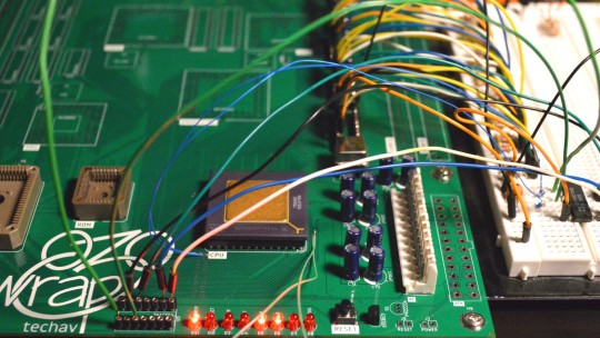
Wrap030-ATX First Tests
The best place to start with assembling and testing a board like this is the power supply. If there's a catastrophic error, like a direct short between supply rails, it's best to find out before wasting other components. Thankfully on this project, I'm using a standard PC power supply so all I need is some basic filtering capacitors. Not much to screw up there except maybe some backwards electrolytics.
Next is generally reset and CPU clock. These are essential for getting the CPU up and running and should be confirmed operational before continuing. Here again I'm using stock modular components — a brownout reset signal generator and a can oscillator — so debugging was minimal.
Finally, the CPU should be tested with these signals to see if it will free run (tie the CPU data bus to a known value, usually something like 0b00000000, and watching to see if the address bus increments freely).

The CPU free run test is an important one. It confirms the most basic functions of the board and the CPU are functional. A board that can't free run at this stage likely has some significant problem that must be solved before anything else will work.
Luckily, it passed this test!
I used the data bus transceiver sockets to attach test wires to, so I could tie all the data bus signals low. On the 68k architecture, $0000,0000 corresponds to the instruction ORI.b #0,D0 which is a 16-bit opcode ($0000) for an OR instruction followed by an immediate constant word ($0000). So for every 32-bit bus access, the CPU is fetching one complete instruction, incrementing the Program Counter by 4, then repeating. The result of the instruction is stored in the D0 register, so nothing is ever written to the bus.
This behaviour can be confirmed with a logic analyzer, but it's easiest to visualize by connecting LEDs to some of the higher address bits and watching them count up in binary (which is what I did here).
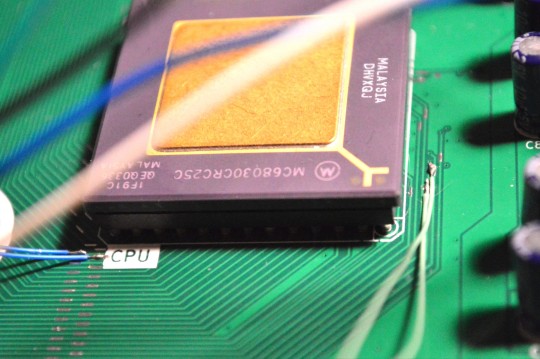
On the 68030 there is a bit more to do than just grounding the data bus. In particular, the CPU's asynchronous bus expects peripherals to report they are ready and have placed valid data on the bus by asserting the Data Strobe Acknowledge signals (DSACKn#). In normal operation, the system will delay asserting these signals to give the peripheral device enough time to do its job, signalling the CPU to insert wait states until the data is ready. For free run though, these signals can be tied low to signal to the CPU that the data it's requesting (all 0s) is ready immediately (because the data bus is tied to ground).
Here is where a last-minute addition to my PCB layout really came in handy. I removed the solder mask on these small sections of important signal traces so I would have a clear place to probe these signals on the top of the board. This also gave me just enough room to solder some 30 gauge wire to the DSACKn# and address signals for running the free run test.
Now that I know the most basic functions of the board are working, I can move on to the next step — running first code. To run real code I'll need ROM working, which will also require the bus controller CPLD to be minimally functional.
I am hoping to have this project at least running BASIC in time to exhibit it at VCF Southwest in Dallas at the end of June this year. I've got a lot of work still to do to reach that goal, but passing these first tests does give me hope that there are no huge show-stopping problems with my PCB (at least nothing that can't be worked around with a bodge wire or two)
#homebrew computing#vintage computing#wrap030 atx#motorola#mc68030#motorola 68k#motorola 68030#vcf southwest#VCFSW
13 notes
·
View notes
Link
Build a multitasking operating system and kernel with an interactive shell!
What you’ll learn
Developing a Multithreaded Kernel From Scratch! Course
How to create a kernel from scratch
How to create a multi-tasking kernel
Learn how to handle malicious or problematic programs in your operating system. Terminating them if they misbehave.
How memory works in computers
The difference between kernel land, userland, and the protection rings that make up modern computing
Kernel design patterns used by the Linux kernel itself
You will learn all about virtual memory and how to map virtual addresses to physical addresses
You will learn how to make the kernel understand processes and tasks
Learn how to load ELF files
You will learn how to debug disassembled machine code
You will learn how to debug your kernel in an emulator with GDB.
Requirements
You must know the C programming language
It is wise to have some basic knowledge of the assembly language
You should have a Linux operating system, free to install from the internet (We use Ubuntu in this course)
Description
This course is designed to teach you how to create your very own multitasking operating system and kernel from scratch. It is assumed you have no experience in programming kernels and you are taught from the ground up.
Real Mode Development
Real mode is a legacy mode in all Intel processors that causes the processor to start in a legacy state, it performs as the old 8086 Intel processors did back in the way.
In the “Real Mode Development” section of the course we start by learning about the boot process and how memory works, we then move on to creating our very own boot loader that we test on our real machine! This boot loader will output a simple “Hello World!” message to the screen and we write this boot loader in purely assembly language.
In this section, we also read a sector(512 bytes) from the hard disk and learn all about interrupts in real mode and how to create them.
This section gives you a nice taster into kernel development, without overwhelming you with information. You are taught the basics and enough about the legacy processors to be able to move forward to more modern kernel development further into this course.
Protected Mode Development
In this section, we create a 32-bit multi-tasking kernel that has the FAT16 filesystem. Our kernel will use Intel’s built-in memory protection and security mechanisms that allow us to instruct the processor to protect our kernel and prevent user programs from damaging it.
We create our own virtual filesystem layer that uses a design that is similar to the Linux kernel. This clever abstraction that will be taught to you was inspired by the instructor’s knowledge of writing Linux kernel drivers in his past.
Developing a Multithreaded Kernel From Scratch! Course
You are taught about the design of the FAT16 filesystem and how the FAT16 filesystem is broken down into clusters and that they can chain together. We then implement our very own FAT16 filesystem driver allowing files to be born!
We implement functionality for tasks and processes and write our own keyboard drivers.
Memory management is essential in any operating system and kernel.
Let us not forget that we even create an ELF file loader, we will compile all our operating systems programs into ELF files and allow the loading of binary programs or ELF programs. ELF files contain a lot of information that describes our program for example where our program should be loaded into memory and the different sections of the program.
By the end of this course, you will have a fully functioning 32-bit multi-tasking kernel that can have many processes and tasks running at the same time. You will have a working shell that we can use as well.
Assembly language bonus
This is a bonus section designed to bring your assembly skills up to scratch should you struggle a little bit with the assembly language in this course. It’s however advised you come to this course with experience in assembly language, we do use it, and its importance. Never the less if you want to take a chance on this course with no assembly experience then this section will help point you in the right direction so you’re able to take what you learned and apply it to the kernel.
Taught by an expert that that has created Linux kernel modules professionally in the workplace.
Download
To download the more paid courses for free visit the course catalog where you get 1000+ paid courses for free without investing money. To download above paid course for free visit the link below.
Developing a Multithreaded Kernel From Scratch! Course Catalog
2 notes
·
View notes
Text
Common debugging problems and solutions after LED display installation
LED full-color display screens are widely used outdoors and are usually assembled from multiple boxes. During the installation and debugging process, some common problems may occur. These problems and solutions are summarized below:

What may be the reasons for failure to load?
A. Make sure the control system hardware is powered on correctly (+5V).
B. Check and confirm that the serial port cable connected to the controller is a straight-through cable, not a crossover cable.
C. Make sure that the serial port cable is intact and that both ends are not loose or detached.
D. Select the correct product model, transmission method, serial port number and baud rate, and correctly set the address bits and baud rate on the control system hardware. Take you 5 minutes to understand the LED display control system.
E. Check whether the jumper cap is loose or fallen off and make sure it is in the correct direction.
F. If the above steps are ineffective, use a multimeter to measure whether the serial port of the connected computer or control system hardware is damaged.
What may be the reason for communication failure?
A. Make sure the control system hardware is powered on correctly (+5V).
B. Check and confirm that the serial port cable connected to the controller is a straight-through cable, not a crossover cable.
C. Make sure that the serial port cable is intact and that both ends are not loose or detached.
D. Select the correct product model, transmission method, serial port number and baud rate, and correctly set the address bits and baud rate on the control system hardware. Teach you the purchasing guide for LED display control system.
E. Check whether the jumper cap is loose or fallen off and make sure it is in the correct direction.
F. If the above steps are ineffective, use a multimeter to measure whether the serial port of the connected computer or control system hardware is damaged.

Why does the system prompt "Please connect the LED display controller"?
In many cases, it is because the LED display control system hardware is not detected during the test time. After connecting the hardware, set the screen parameters in the software, close and reopen the software to ensure the connection is successful. What are the supporting equipment for LED display screens?
Everything is normal on the controller but there is nothing on the display?
A. Make sure the LED display is powered on normally.
B. Check whether the connection between the HUB distribution board and the display screen is reversed.
C. Check whether the edited and sent program is empty.
The entire screen of the unit board is not bright or dim?
A. Visually check whether the power connection cable, the 26P cable between the unit boards and the power module indicator light are normal.
B. Use a multimeter to measure whether the voltage output of the unit board and power module is normal, and make fine adjustments to meet the standards.

What is the reason for the black screen on the LED display?
A. Make sure all hardware is powered on correctly.
B. Check whether the serial port cable connected to the controller is loose or detached.
C. Confirm whether the connection is correct, including whether the connection between the HUB distribution board and the display screen is tightly connected and not reversed.
What does automatic or manual brightness adjustment mean?
Brightness adjustment is to adjust the darkest to brightest range of the display screen. Automatic brightness adjusts the predetermined brightness according to the time period. Manual brightness is set by user operation. How to adjust the brightness and contrast of LED display?
The assembly and maintenance of LED displays are technically demanding and meticulous. Good assembly and maintenance techniques directly affect the service life and performance of the display.

Thank you for watching. I hope we can solve your problems. Sostron is a professional LED display manufacturer. We provide all kinds of displays, display leasing and display solutions around the world. If you want to know: The difference between LED advertising vehicles and LED mobile stage vehicles. Please click read.
Follow me! Take you to know more about led display knowledge.
Contact us on WhatsApp:https://api.whatsapp.com/send/?phone=8613570218702&text&type=phone_number&app_absent=0
0 notes
Text
rk1700 december day 10, 27: structure, home
written for @rk1700december. day 10: structure; day 27: home
rhea is female connor. cronos is rk900.
also on ao3
----
‘Uh, Cronos? Reed left something for you before he left. Please come and retrieve the package.’
Cronos’ gaze lands on Rhea who has been resting in bed since returning from her… impromptu debugging with the Administrator. He reaches for her through their connection and tells her what he will do and where he will go, and when all she does is burrowing deeper into the nest she has made out of a few blankets and some spare clothing, he takes it as an affirmative and, after curbing his anxiety that threatens to overtake him whenever he has to leave Rhea for any length of time, he goes to the coordinates attached to the message and finds a box as wide as his shoulders waiting for him.
‘All of this?’ he gestures at the package. ‘And who is Reed?’
‘Yes, all of it is yours, and you might know him as Elijah Kamski. He isn’t exactly subtle about his true identity, unlike most Council members.’
Cronos nods and takes the box with some customary expression of gratitude. He gives it a shake, hearing the content click against one another and feeling the shift of the centre of mass and the weight. More plastic just like the frame of his bed, but this one is much smaller and much more closely-packed. He gives it one more shake just to hear the sound again and goes back to his quarters.
He sits on the floor with the box in his lap, and before he can interface with the seal and unlock it, Rhea somehow manages to sneak up on him and hook her chin onto his shoulder which of course startles him, but he calms down quickly enough.
‘Let’s see what Elijah got for us, shall we?’ he says to Rhea. Sure, interfacing might be more convenient and power-saving, but there is something about talking and making his actions known to other people that just… seems more attractive. As if they weren’t that alone in the solar system.
Rhea nods (or as much as she can in this position anyway). Deactivating the skin on his hand, Cronos establishes a connection with the seal of the box, and a hologram of a mini Elijah pops up. ‘Hi, Cronos, Rhea,’ it says. ‘I noticed that Anchor and the Administrator were keeping a lot away from you, even the essential stuff you need to understand a bit of what’s going on. There also isn’t much for you to play with apart from blocks so…’ holographic Elijah shakes his head with a chuckle. ‘More blocks for you, I guess. Mind you, this one is much more delicate and detailed, so don’t throw them around like your normal blocks.’
The hologram disappears, and the box starts unfolding itself neatly to reveal a neat stack of plastic parts ready to be cut out and assembled into… something. Cronos interfaces once more with the box, now no more than a thin polygon created out of malleable synthetic fibre with electronics weaved into the threads, and finds the construction manual. That is when he opens a connection with Rhea and sends it to her as well even though it is highly likely that, without direct interfacing, she won’t be able to process it and merely logs it as another minuscule change in her system - everything is compared to the vast memory storage she has and cannot access. The comment about Anchor hiding things away from them gives him a bad feeling about his surroundings but he decides to not look too deep into it for now; he’s got something to build.
Let’s see, he carefully untangles the pieces of plastic from one another and spreads them out onto the floor. We need a piece of this from here, another piece from there, and then we’ll need to join them together before putting it onto there…
A few hours and a half-hour break to coax a bottle of thirium into Rhea later, the model of the facility is finally taking shape. Sure, the classified and off-limits sections and wings of the site are still represented by larger chunks of plastic, but it is detailed and delicate when it comes to the places they are free to access, and he can imagine a miniature Anchor in the shooting range, the facility’s personnel having meals together - no matter android or human - in the canteen, he and Rhea watching the shuttles depart and taxi from the viewing deck next to the landing pad. There even is a model of a shuttle which Cronos can easily control and make float in midair with his biotics. He leans back, realising that the model is almost finished, and gives a larger piece to Rhea. Care to do the honours? he asks through their link.
Rhea accepts the piece slowly and then holds it in her palm. Right. Processing power. Cronos holds her other hand with his bare hand, initiating an interface, and shares the isolated instruction for the part with her. Eyes widening in recognition, Rhea easily slots the component into where it should be, and, without breaking contact, she assembles the rest one-handedly with occasional help from Cronos. He suspects some of the pieces are magnetic as they automatically snap to their place as long as they are held close to where they are supposed to be, and he adds ‘express gratitude to Elijah’ into his to-do-list simply because of how happy Rhea looks, how she turns her head to smile at him after each piece is secured in place, how - for the first time since Cronos met her - she can set her pain aside for the shortest while; yes, even when they couple and Cronos is deep inside Rhea and they can be the closest to each other, the agony that is everyday living does not fade for her.
But now - but now -
The final piece. It is small, it should have been handled with extra care and probably with the help of tools, but Rhea looks so determined to put it onto the model that stopping her would have been a crime in itself, and the slight fear of her dropping the piece in the structure will prove to be futile; it snaps to its place with a small click, the lights in the room dim with a low thrum, and the places where the generators of the facility should be glows, thin lines of blue emerging from the rooms to complete the final piece of the model by forming into people and equipment too small to be represented by actual parts. With a glowing hand, Cronos directs Rhea’s bare finger to tap a corner of the structure they just assembled together. Examining the model and pointing out the movements of holographic people don’t exactly answer the many questions they have, but it is a reminder of their home, something familiar amongst so many uncertainties and secrets.
Look, Rhea points at a hologram. That’s us.
Cronos squints and sees a tiny version of the two of them playing with blocks. Their facial features are grainy and pixelated just like the others, but he thinks that they are happy. Just like themselves.
Yes, Rhea, he draws her into the space between his legs and envelopes her in a hug. That’s us.
4 notes
·
View notes
Text
The true secret To Successful Product Improvement In addition to Support

Blog Developing some sort of new software program product/application or perhaps adding the latest feature in order to the existing you are able to possibly be overwhelming. The development crew requires evaluating their attempts shrewdly to make merchandise development a prosperous task. By complex performing environments to be able to technical complications, and assist services, quite a few factors have an effect on a software solution layout. But, with concentrating on00 the actual details, the team could point development and help support practice higher.
Blog
Market Alignment
Having market orientation, most of us necessarily mean identifying and assembly consumer's expectations and needs. A program development team really should provide for conducting comprehensive end user analysis and market study to gain experience straight into customer's desires. By means of setting out their preferences and also finding what features many people accurately want in a item, the development team can give high-quality user emotions.
Growth Strategies
Having a new strategized method for getting a new product is actually something which you can not overlook. Building a new product or service requires dividing the duties involving product designing, operations, along with development teams. Encourage the style and design team to provide many input into the intended approaches and conduct person exploration to ensure this it is fulfilling wearer's needs. Though product managing team will have for you to move in the ideal direction, designers can certainly decide and guide coders to help ensure superior products.
Technological know-how Executed
It is important to ensure that the particular technology you are using intended for creating the merchandise is suitable for the industry. Design teams should pick out technology by keeping the end-user in mind. Oftentimes, for instance, a program owing to expensive software/hardware demands could become inaccessible in order to consumers whilst staying acquireable to the corporate stores.
Product's Functionality
Let's find this actuality very clear- a software have their own restriction in terms of utilities. You won't add every sole feature you think could possibly enhance any software's features. Sometimes even though adding scores of complex functions, you actually may end up acquiring a elaborate software using multiple anomalies. In form a contrast, probably some of your own personal clients might have expected for putting multiple capabilities, but this could not have an impact on the main target involving making a software do the job just as required. Outline some sort of strategy and commence with improving upon software efficiency, maybe by fixing main functions or maybe debugging a whole new feature while users come across functionality considerably more important than a new added feature.
Feature's Simplicity
If the main purpose of your small business will be to develop a remarkable application, the best matter you can do is usually to review its feature's usability. What is usage connected with the added features if they can be taken away without which affects software's operation. As a matter associated with fact, cardiovascular disease you will certainly keep a product a lot, the faster applications may run. Plus, it can make software development finer. In addition , focus on introducing valuable characteristics instead regarding increasing their statistics seeing that a customer makes typically the shopping for decision only by means of investigating a software's level of quality, definitely not the extra attributes which are useless.
Coding/Programming
If the product is definitely by now working fine having an standard programing words, that's fully fine. Have a tendency re-code it merely requires to produce it purely web-based. Placed priorities by diving in customer database and make a requirement list prior to be able to adjusting the user screen. Certainly, doing some security and safety and computer software changes are usually mandatory hence the product may run competently on several operating systems.
Progress Acceleration
Unless the development staff is able to get products speedier in often the market, the company still cannot be ahead of all their competitors. Guess, you are generally taking 4-5 decades for you to develop a product, although it normally takes 1-2 several years for your challengers to get the same product, your personal solution more likely will probably fall in vengeance involving having great designs.
Be able to balance your product designing and development speed whilst ensuring good user experience.
Software Migrations and Upgrades
Balancing concerning software migration and repair, sometimes cause several difficulties which later causes much larger problems, and put all people in jeopardy until it obtains resolved. The easiest way to avoid that is to make small changes during a program estivage or new let go. Simply, keep away from doing sychronized migrations as well as subsequent migrations while relocating existing databases to more modern applications. In addition, ensure the of plan developer to help software improvement and complications occurred while in the migration.
Closing thoughts
Aforementioned factors usually are vital for ensuring a profitable tool and support. Generally be sure that the product making, management, in addition to development competitors are working throughout balance. Though the design workforce can influence some connected with the components majorly, teaching customer's prerequisites play a new critical role with making certain project success.
1 note
·
View note
Text
The role of hydraulic parent machine (how much is the Shandong mother row pressure machine)
With the deepening of people's understanding of the ring -shaped buser, the demand for equipment in the market is constantly improving. However, people should pay more attention when they are actual. Meet the requirements. So, what are the problems of the choice of ring bus machines? Let me introduce it to you.
The role of the hydraulic parent discharge unit adopts the plum blossom to eight or four modes of the plum tower. The cutting of large tonnage oil cylinders, the cutting surface of the cutting workpiece is vertical, the oil pump preparation pressure is reduced, and the service life increases several times.
In the field of textile industry, the parent line equipment is one of the equipment types with strong application requirements. With the continuous growth of productivity demand, the application requirements of this product are constantly improving. In order to better adapt to this change, the parent line machine product has also undergone a large update, while the Yunbu pavement machine is a manifestation of the latest results. Compared with the traditional bus device, what can its performance advantage roughly understand from?
Before the operation of the numerical control bus machining machine, first check whether each operating station, limited switch, pedal switch, emergency stop button, etc. can be flexible and fastened to ensure the safety of the equipment. Injecting oil in time in time according to the usage. The operators of the bus processing machine must concentrate their efforts during their homework to avoid the occurrence of safety accidents.
In order to improve the service life of CNC BUSBAR MACHINE, the use environment of the homeline processing machine generally requires the direct irradiation and other thermal radiation of the sun, and to avoid places with too humid, too much dust, or corrosive gases. Punching, forging equipment, etc. The role of hydraulic parent machine
Pay attention to the accumulation of work experience in the usual assembly work, and know the operation of each part, each part of the operation. Therefore, it is not difficult to learn. Because many parts and parts are processed by foreign associations, there are inevitably some problems. During debugging, it is difficult to find the problem where the problem is, which part cannot be operated normally, or if there is no action, or if the movement is not flexible, you will take a lot of detours. Time to deal with the problem. Usually I follow the master slowly, watching how they do it, encounter every problem, how to deal with it, and write down each question carefully. When you debug yourself independently, it is easy to solve the same problem when you encounter the same problem. It's right.
The role of the parent line processing machine of the hydraulic parent machine is a supporting equipment designed by reference to advanced foreign products and combined with domestic reality to improve work efficiency and ensure the safety of operational safety. In order for everyone to better use the homeline machining machine, let me introduce the maintenance of the homeline processing machine.
Secondly, before the purchase of the bus processing machine, the suppliers must provide various original materials and repair materials provided by the equipment. It is better to grant people and fish than to give people fishing. After learning about these materials. Being able to understand the production manufacturers' production and design. If the operations are negligent, many unnecessary costs will occur after the equipment is put into production.
0 notes