#chamfer plane
Explore tagged Tumblr posts
Visit Tumblr Blog
Explore Tumblr blogs with no restrictions, modern design and the best experience.
Last Seen Tumblr Blogs


Fun Fact
1,644 Tumblr posts in 1 second.
Text
The last time I posted about my office, I had just redone the desks and gotten them stained and into more or less their final configuration. That was January 18, 2021. January 24, 2021, I ordered this Object:

The Linon Home Decor Products Casimer 6-Drawer Wide Rolling Home Office Storage Cart, Natural.
The thing about this cart is, it looks like raw pine! Just plain ass wood. Nothing special. That's what made me want it, because I wanted to make it match my new desks.
The thing about this cart is, it is not raw fucking pine. It is covered in some sort of truly evil matte plastic coating, like a super flat polyurethane or some shit. I immediately set about trying to strip it...and gave up. Hard. To the point where I almost literally do not have pictures until I got to this stage:

Basically, that polyurethane was a bitch to get off. I had to buy a random orbital sander, 60 grit pads, citristrip and serious elbow grease. @dustycymbre came in clutch with powerful techniques.


Through perseverance, muscle and a lot of cussing, we got it done. I routed the top panel to be a square match to the sides and then added a chamfer to the top, and we stained it to match the desks. I also made some matching shelves of the same red oak the desks have:

And then the scope crept, because I realized if I simply moved the desk out of the way, not only would mounting the shelves be easier, but I could also PAINT THE WALL


Then it was shelf time.


This really helps me feel some control in my life, and our office is now a wonderful source of happiness for me. It's so lovely to hang out in there with all the warm woods and my silly steampunk theme and the bright bright purple shining in the sunlight and glowing warmly in the chandelier's LEDs.


Also I got us new fancy monitor arms and set up Switch docks on HDMI switchers so we can game on our monitors side by side! I'm literally living the dream it's fucking awesome. This room absolutely rocks now.


Thank you for reading, here's Ghira seeing every plane of existence overlapping in a swirling mobius
#my crafts#desks#woodworking#old house#oh fun fact i learned from the fire map that this bitch is from like the 1860s#taigh a' cheartais is old as shit y'all#over 160 years if I counted right
18 notes
·
View notes
Text
Japanese chamfer plane mystery solved after 12 years
Back in 2011, I wrote a post about my Japanese chamfer plane. It’s a quick and easy way of creating a defined 45º bevel on a corner of a board. Every Japanese chamfer plane I’ve seen has a scale like this on it, with two sets of measuring marks.
The reason for the “A” and “B” scales has puzzled me over the years. The best explanation I could come up with is that the “A” scale provided the width of the chamfer made by the plane, while the “B” scale was a measurement of how much of each face of the corner would be removed to get a chamfer of a certain width. Here’s a drawing that illustrates my alleged cleverness.

On my visit to Inoue Hamono, I was able to get a more definitive and straightforward answer about this from Toshio and Masatoshi Inoue. The “A” scale is based on traditional Japanese units of length. Each mark is 1/2 of a bu (分), which is about 3mm. The “B” scale is in millimeters. Each scale is used to set the plane to cut a chamfer of the length you want, depending on the system of measurement you are using.
Toshio and Masatoshi also told me that you should ignore this scale and use a proper ruler instead. I found that hilarious.
I redid my math, and it turns out that if the length of the wood on one face of the board is, say, 5 tick marks on the “B” scale, then the length of the chamfer created is very close to 5 tick marks on the “A” scale. This is just coincidence. There are Japanese chamfer planes that will create a 30º chamfer on the corner of a board, and this conversion would not work on that sort of plane.
11 notes
·
View notes
Text
@taddymason These are so cool! I love how beautifully you've captured all the little shapes that define their forms, and I wanted to highlight two cool elements I saw

I love the visibility of the tiny flecks of impurities that almost look like bubbles in a soda here, and the way the highlight continues down the slightly chamfered edges of the planes. Also the effect of what I think must be a piece of reddish stone affixed to the rear of the crystal? The shape that shows almost looks like a person sealed away inside the crystal, and that's very cool and inspiring.

on this crystal I love how clear it is that the green parts of the crystal are translucent in that you can see the walls of the white material descending through. I also love how the highlights communicate the form of this rounded crystal, and while it might be just where cloudiness in the material itself coincides with the highlight, but it looks like the sky is being reflected on the crystal's surface?
Very cool work, I should do more studies.
Crystals study


i'm so tired
52K notes
·
View notes
Text
How to Create a Game-Ready Car 3D Model Step-by-Step Guide

Creating a game-ready car 3D model is a must-have skill for any aspiring or professional 3D artist working in the game industry. Vehicles are a staple in racing games, open-world adventures, and simulation experiences, and when crafted properly, they become high-impact 3D game assets that elevate the entire experience.
In this guide, we’ll walk you through each essential phase of the process, from initial planning to final export. Whether you're a beginner or brushing up on your workflow, this breakdown will help you master the art of 3D vehicle modeling using best practices in hard surface modeling.
Step 1: Collect References and Analyze Design
Before opening your 3D software, gather visual references. This includes orthographic blueprints, real car photos, and concept sketches. Analyzing how cars are built in real life helps in understanding form, proportions, and technical details.
Why this matters: Creating believable assets for 3D modeling games starts with strong reference material. Your model should reflect the theme and style of the overall 3D game environment it will exist in.
Step 2: Blocking Out the Base Mesh
Start with a simple block-out of the car’s overall silhouette using primitive shapes like cubes and planes. Don’t worry about details yet—focus on getting the scale and major forms right.
Goal of this stage:
Build a solid foundation for your car 3D model
Ensure proportional accuracy
Maintain a clean topology for later stages
This early layout serves as the backbone for your future 3D hard surface modeling steps.
Step 3: Sculpting the Body with Hard Surface Techniques
With the block-out complete, begin shaping the panels, hood, roof, doors, and other core sections. Use bevels, loops, and chamfers to define crisp edges and clean transitions.
This step falls under Hard Surface Modeling, which is the backbone of creating realistic mechanical assets like cars, weapons, or architecture in 3D modeling games.
Tips:
Stick to a quad topology for smooth subdivision
Minimize polygons without sacrificing form
Model with the game engine’s performance in mind
Step 4: Modeling Accessories and Props
Once the car body is done, add smaller components: wheels, mirrors, headlights, grills, wipers, and interior seats. These are treated as separate props 3D model elements but must blend visually with the main mesh.
Each part should be optimized to function as reusable 3D game assets, especially in modular systems used in large-scale 3D game environments.
Step 5: UV Mapping and Baking Details
After modeling, create a well-organized UV map. Use overlapping UVs where possible to conserve texture space, especially for symmetrical parts like tires.
Next:
Bake high-resolution details into normal maps
Baking is a critical step in 3D environment modeling, allowing detailed visuals while keeping your 3D vehicle modeling light and engine-ready.
Step 6: Texturing the Car for Games
Use a PBR (Physically-Based Rendering) texturing workflow to apply realistic materials like metal, paint, rubber, and glass. Tools like Substance Painter or Quixel Mixer are ideal for painting directly onto the model.
Texture sets usually include:
Albedo/Base Color
Roughness
Metallic
Normal Map
Ambient Occlusion
For 3D modeling games, optimize texture resolution—2K is ideal for most in-game cars. Keep your materials performance-friendly while still being visually rich.
Step 7: Rigging and Exporting
If your car has movable parts—like spinning wheels or opening doors—add simple rigging or object parenting to allow for animation in-game.
Final checks before export:
Set the correct scale and orientation
Freeze transformations
Export in engine-friendly formats like FBX or GLTF
Step 8: Optimize for Real-Time Performance
Your car must look great and run smoothly. Reduce unnecessary geometry, use LOD (Level of Detail) models, and make sure your UV layout avoids wasted texture space.
Optimization ensures your car 3D model can be used efficiently alongside other 3D game assets and props in large-scale 3D game environments without impacting frame rate.
Final Thoughts
Creating a polished, optimized, and visually impressive 3D vehicle model isn’t just about sculpting a cool car—it’s about understanding how the asset will function within a broader 3D game environment.
By combining solid hard surface modeling techniques with UV efficiency, baking, and real-time optimization, you’ll produce 3D game assets that perform flawlessly and look fantastic. Whether it's for a racing game or an open-world sandbox, a well-made car adds immersive value and dynamic gameplay opportunities.
#3d game environments#hard surface modeling#3D game assets#3d vehicle modeling#props 3d model#3d modeling services
0 notes
Text
A Legacy on the Wrist: Introducing the Peacock Perfection Classic 1950 Chronograph

For discerning horology enthusiasts and admirers of timeless military design, we at Peacock Watch are proud to unveil a timepiece that embodies both heritage and innovation: the Peacock Perfection Classic 1950 Chronograph [Limited]. This exceptional watch is more than just an instrument for telling time; it is a meticulously crafted tribute to the robust elegance of military watches from the Korean War era, reimagined with modern precision and unparalleled artistry. As China’s first high-end military chronograph, the Perfection Classic 1950 sets a new benchmark in horological excellence, seamlessly blending historical inspiration with contemporary craftsmanship. The journey to create this remarkable timepiece involved months of dedicated refinement, a testament to our unwavering commitment to quality and detail.
The Art of Movement and Dial

At the heart of the Perfection Classic 1950 lies a movement that exemplifies the pinnacle of mechanical engineering. The movement bridges are adorned with exquisite Geneva stripes, their unique luster reflecting the meticulous care taken in their finishing. Ensuring impeccable accuracy, the swan neck regulator offers precise timekeeping adjustments through its gracefully polished curves. This fusion of classical nobility and modern craftsmanship pays homage to the esteemed traditions of haute horlogerie. Further showcasing the dedication to detail, the Y-shaped bridges are hand-finished with circular chamfering, imparting a soft sheen while effectively reducing stress, thereby enhancing the overall durability and stability of the movement.
The dial of the Perfection Classic 1950 is a work of art in itself. The Arabic numeral hour markers are an innovative design conceived by our brand, drawing inspiration from the revered Chinese "Eight Great Techniques" of chasing. These numerals capture the very essence of ancient calligraphy, embodying the nuanced pauses and deliberate brush strokes. Each numeral is meticulously carved, conveying the profound spirit of Eastern culture and adding a unique dimension to the watch’s aesthetic.
Exquisite Craftsmanship and Military Heritage

Comfort and sophistication extend to the strap, which is crafted from select NOVONAPPA calfskin. This premium leather is known for its supple texture and fine grain, ensuring a luxurious feel on the wrist. Employing a technique reserved for the highest quality leather goods, the strap features meticulous hand-stitching. The waxed thread is densely and evenly applied to the leather surface, with secure knots reinforcing the integrity of the construction. This not only beautifully highlights the delicate texture of the leather but also provides long-term durability, a testament to our relentless pursuit of superior quality in every detail.
The chronograph function of the Perfection Classic 1950 boasts a sophisticated horizontal clutch architecture. This intricate design aligns the chronograph’s second-hand drive wheel, clutch wheel, and running seconds hand on a single plane. This configuration not only offers a captivating view of the chronograph’s intricate mechanics in action but also contributes to precise and reliable timekeeping. Adding a touch of timeless elegance, the hands of the Perfection Classic 1950 feature the distinguished art of bluing steel. This time-honored watchmaking tradition, synonymous with luxury, is executed with meticulous care by Peacock’s skilled artisans.
Further enhancing its connection to its military inspiration, the Perfection Classic 1950 is equipped with an innovative rangefinding bezel, drawing inspiration from historical artillery instruments. This lightweight and precise feature allows wearers to appreciate the ingenuity of military tactics from the past, adding a layer of historical significance to this exceptional timepiece.
A Timeless Masterpiece Awaits

The Peacock Perfection Classic 1950 Chronograph [Limited] is a testament to our unwavering dedication to horological excellence. It is a watch that seamlessly blends the rugged charm of military aesthetics with the refined precision of modern watchmaking. From the meticulously finished movement to the thoughtfully designed dial and the luxurious leather strap, every detail speaks to our commitment to creating timepieces of exceptional quality and enduring beauty. This limited edition chronograph is not just a watch; it is a legacy on the wrist, a tangible piece of history reimagined for the modern era.
Shop Now and Own a Piece of History: [Peacock Perfection Classic 1950 Luxury Chronograph Watch]
Embrace the Legacy. Command Time. Acquire Your Perfection Classic 1950 Today!
#peacock#tourbillon#jewellery#luxury watches#timepiece#luxury#peacock watches#chinese watch#peacock 1950#watch#watches
0 notes
Text
Understanding CAD Modeling Approaches in SolidWorks: Cross-Section vs. Features

When it comes to creating parts in CAD software like SolidWorks, designers often dive straight into modeling without giving enough thought to the best way to approach the task. However, planning and strategising before creating a CAD model can lead to faster creation, easier editing, and better alignment with manufacturing processes. In SolidWorks training online, the words “model” and “part” are used interchangeably.
Key Factors for a Good Modeling Plan
A modeling plan is considered effective when it meets the following:
Fastest time to create the part
Ease of editing the part later
Alignment with how the part will be manufactured
These strategies are deeply discussed in any professional SolidWorks online course, helping learners build the right mindset from day one.

Two common approaches are used in modeling: the cross-section approach and the features approach.
Cross-Section vs. Features Approach
Cross-Section Approach: This is generally quicker. You sketch the entire part profile and extrude it in one go. However, it might be harder to edit later if changes are needed.
Features Approach: This method builds the part step by step, like creating a block, chamfer, and hole. It mirrors how a machinist would make the part in real life, starting from a block and then working step-by-step. While it may take longer initially, it’s more modular and easier to modify.
Many SolidWorks online classes explain both these approaches in depth with examples. Whether you're attending SolidWorks training online or self-learning through videos, understanding both styles is a must.
For example, take a chamfered block with a hole. In the cross-section approach, the sketch would include all the features (like the chamfer and the hole) in one sketch. In the features approach, you would first create a solid block, then apply a chamfer, and finally create the hole. Each of these is done as a separate feature.
Personal preferences and industry experience often influence this debate between speed and modularity. Designers with a manufacturing background may lean toward the features approach because it better reflects how parts are made in the real world.
Creating a Part in SolidWorks
Once you’ve chosen your modeling strategy, the next step is to use a CAD/CAM system like SolidWorks to create the part. This is a major part of what SolidWorks classes online focus on for beginners and intermediate learners.
SolidWorks builds a part using features. A feature can be an extrusion, a hole, or a revolve. When you add a feature, it combines with existing features to build the full 3D part. Each new addition updates the model in the feature tree.
Basic Features in SolidWorks:
Extrusion: Creates a shape with uniform thickness.
Revolve: Creates a shape by revolving a 2D sketch around an axis.
The feature creation process begins with a 2D sketch. You sketch the profile on a selected sketch plane and then use it to create a 3D feature.
SolidWorks provides two tabs: the Sketch tab and the Features tab. You can start from either tab, but starting from the Features tab is often considered more efficient because it automatically guides you into sketching mode.
Example Walkthrough
Let’s look at a simple plate example:
Create Sketch1: Select Top Plane > Use Center Rectangle > Smart Dimension for sizing > Exit sketch.
Create Block Feature: After exiting, enter the thickness (e.g., 0.5) and finish. Rename the node to “Block” and save the file.
Add Hole Feature: Select the top face of the block > Extruded Cut > Draw a circle from the origin > Dimension it (e.g., diameter 1) > Enter thickness (0.5) and finish. Rename the node to “Hole.”


This step-by-step approach mirrors what’s covered in SolidWorks training online, making complex parts easy to build.
Conclusion
In summary, the choice between the cross-section and features approach in CAD modeling depends on your goals—speed or flexibility. For educational purposes, especially in SolidWorks online class modules, using the features approach helps learners understand part creation more deeply by breaking it into manageable steps.
If you’re looking to build your skills in SolidWorks and learn both these modeling approaches with hands-on practice, check out the SolidWorks training course online. It's a great way to strengthen your CAD knowledge and get industry-ready.
0 notes
Text
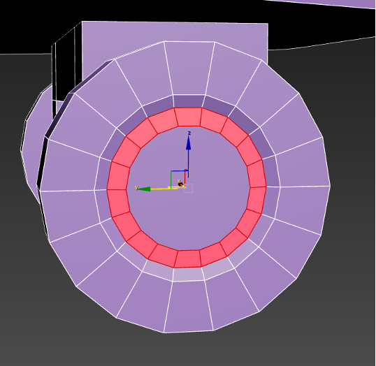
The First Project Part 3 (Unwrapping)

We're creating smooth edges and hard edges. The hubcap's seams should be hard, but the outer ring of it should be smooth.
Select the ring, then auto smooth.

I've smoothed the other ring too, then i hardened the edges between the tire and the final ring.
Select an object a part of the whole plane, then go into F3 to kind of isolate it. I'm just checking I've beheaded the cylinders.

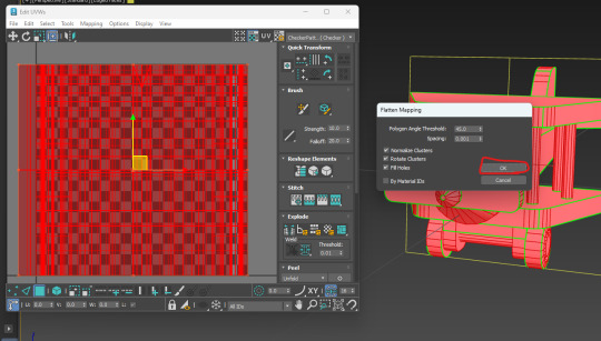
Applied the UVW unwrap modifier.
Ctrl A, select all faces

2. Flatten Mapping.
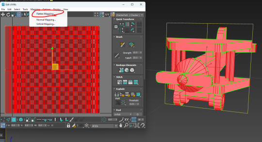
3. Slarp ok button.
Now we have some edge, face, and vertex select for this screen separate from the main 3ds editor.
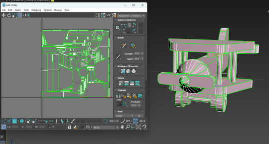
Moving the UVs out of the area.

Now select the tail fin in the main 3ds and that will select it's islands in the UV editor. I drag them out of the main cluster.

Click the edge of this chamfer, then click stich custom.

That will stich the disconnected parts back together as they connect on the model itself.
As you can see here, these two edges connect on the model, but are disconnected in the UV unwrap. This is why I will use the custom stich tool, to bring these back together.
After connecting the cone's edges click straighten selection (I've been doing the simple connections for the rest of the things).

actually don't do that last step that will fuck shit up. Instead break off these bits using the break tool, then flatten the skirt, then re-stitch the stuff back to it.
the result.

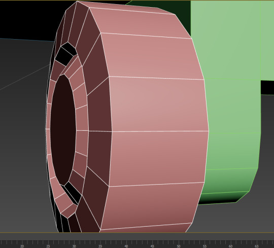
Disconnect the hub from the wheel.

for the smaller bits, select their origin (the outer ring), hen click quick planar map to connect them up.
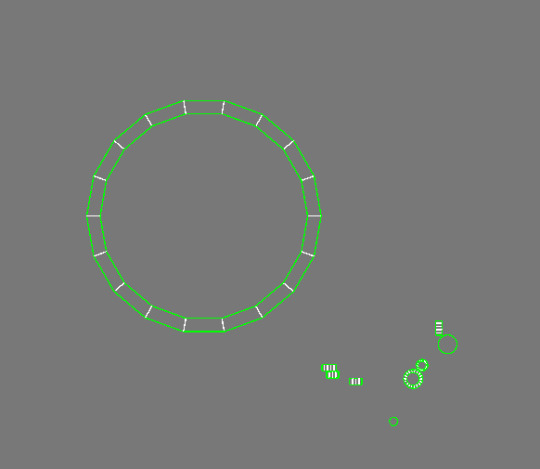
I'll get this giant circle, but the size doesn't really matter.
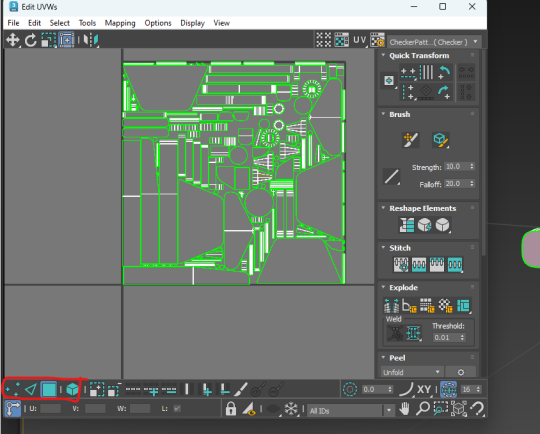
For packing to ensure maximum space is used I must break some parts into smaller pieces:

These long pieces can be split near the middle using the break tool, these are the seams I'm splitting. There's some wasted space in that top right area.
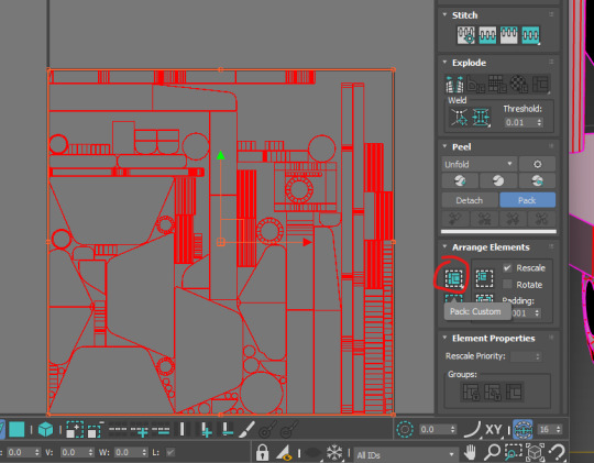
Now I repack the whole thing (I forgot to document packing, but basically you just ctrl+a all the islands then click pack custom).

Now you can see some of the wasted space is reduced, though it might be required to cut down on some more pieces to squeeze a little more space, maybe not though.
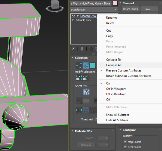
Now we right click on unwrap UVW and collapse all.
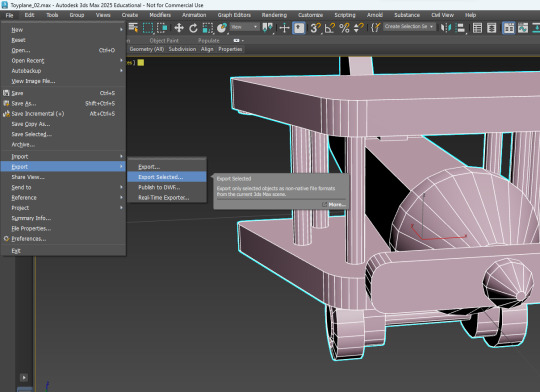
export.
sexport.

Going to Substance painter
0 notes
Text
Finishing Touches
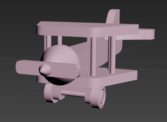
For the last few modeled parts, I thought I'd pull them all together, since they are rather short 'n sweet.
..............................................................................................................................
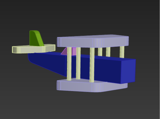
For the rods on either side of the planes wings, we duplicated a cylinder three times, spacing them out into a triangle shape. Then, with one cylinder still selected, we navigated to the right side of the screen and clicked the 'attach' button. We could then go around and click the other two pillars. This would combine the meshes together. You'll be able to tell if this endeavor was successful by clicking one of the pillars and having all three light up. A successful combining:

Then all that had to be done was mirror the object, which had to be done in a way that felt rather non-intuitive, but worked none the less.
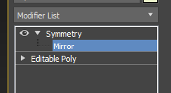
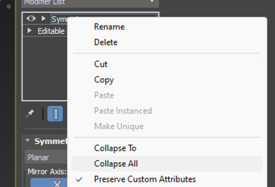
By accessing the 'modifier list' above the objects parameters, we could click the inbedded list and scroll through till we found symmetry. Once symmetry was added above our object mesh, we could click it's drop down and select mirror. Then using W,E,R, it's as easy as pulling on the mesh which will essentially duplicate it, but mirrored. To clean up, we can also collapse (basically a fancy way of saying merge) the symmetry drop down into our mesh to solidify it into one object. The many, many drop-downs needed to get there:
..............................................................................................................................
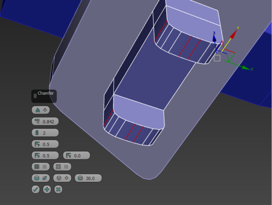
For the wheels and axle, we stuck a box on the underside of the bottom wing and added two cuts into it using the connect button (just like we did for the plane body). This time, instead of sliding the cut, however, we pinched it instead, allowing us to manipulate it and move it equally across the box. Cuts made in equal measure:

From there, we extruded the two faces either side of the cut, which adds protrusions to the original box shape, something I was familiar with thanks to last year. The height could be adjusted, and then I chamfered the edges for that nice rounded appearance.
Side note: Extruding is ten times easier in 3DS Max apparently. It tended to just... break a Maya model. Extruding protrusions:

Adding the wheels was simple. All we had to do was add a large cylinder, and inset three inner circles into it– another option that becomes available through the click of a button once the item becomes a polygon. All of this was create the illusion of hubcaps and depth on our wheels. Adding insets to the wheels to create a hubcap:
With three insets, I could double-click and use W,E,R to drag back the middle on to create a nice hubcappy illusion. I was pleasantly surprised at how nicely this worked.
The single wheel could then be duplicated and flipped using W,E,R. I chose to snap mine to my plane for accuracy, though it could have just as equally been eyeballed. A hubcap!:
And, for a little extra flare, we smoothed out the faces we created, to get rid of the janky hard-edged looked. This was as simple as selecting the ring of faces we wanted, and going to the bottom right to apply an auto-smooth. The smoothing process:


..............................................................................................................................
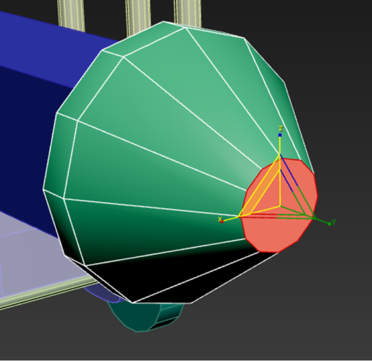
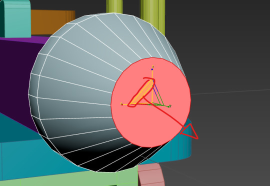
The final little pieces were the front cone and propellers! The propellers were easy, just another box that got the chamfer treatment, but the cones were actually a little different.
Instead of using an actual cone primitive shape, we used a simple cylinder. By cutting a connecting loop into it and sliding it down to the base, we could then select the front and scale it using W,E,R. This was the top wouldn't be entirely pointed! Though be sure to use the triangle between the side and up arrows, this ensures you'll pull the mesh in and down in a pinching motion.
Cone-ception! It's actually a cylinder:

..............................................................................................................................
0 notes
Text
Automatic milling slot plane drilling chamfering tapping machine
0 notes
Text
What is a Jack Plane : The Ultimate Guide to Mastering Woodworking with Precision
A jack plane is a woodworking hand tool used for leveling and flattening wood surfaces. The jack plane efficiently removes excess materials, leaving a smooth and even finish. It is an essential tool for carpenters and woodworkers to shape and refine their projects. With its sharp blade and sturdy construction, the jack plane is able to handle various types of wood and achieve precise results. Whether you are smoothing rough timber or preparing boards for joinery, the jack plane is a versatile tool that enhances the quality and accuracy of woodworking projects. Its ergonomic design and ease of use make it a popular choice among professionals and hobbyists alike.
The Evolution Of Jack Planes
Welcome to our blog post on the fascinating evolution of jack planes! In the world of woodworking, these versatile tools have undergone significant changes over time, adapting to the needs of craftsmen through innovation and technological advancements. In this section, we will explore the transformation of jack planes, from their early days as hand tools to their integration with power tools.From Hand Tools To Power ToolsJack planes have come a long way since their humble beginnings as hand tools. Traditionally, these planes were manually operated by craftsmen, requiring considerable physical effort and expertise. Carved from high-quality wood or iron with a sharp blade embedded in the body, hand-operated jack planes were essential instruments in shaping and smoothing wooden surfaces.However, as technology progressed, power tools revolutionized woodworking. Electrically powered jack planes were introduced, signifying a significant shift in the efficiency and ease of woodworking tasks. These power-driven planes utilize motors that rotate the cutter, enabling craftsmen to work more quickly and accurately. Now, woodworkers can achieve precise and smooth finishes with reduced physical exertion.Importance Of Jack Planes In Woodworking HistoryThe evolution of jack planes is not only a testament to human ingenuity but also highlights their enduring significance in woodworking history. Whether they are hand-operated or powered, jack planes hold a crucial role in the craft, as they perform several vital functions that make them indispensable for woodworkers.Firstly, the primary purpose of jack planes is to flatten and level uneven surfaces, ensuring that the woodwork is uniform and free of irregularities. This is especially important for larger projects where precision is paramount.Secondly, jack planes excel at removing excess material, allowing craftsmen to shape and mold wood to their desired specifications. Whether it is chamfering edges or creating beveled surfaces, these versatile planes are indispensable for achieving precise and unique designs.Lastly, jack planes are valuable tools for smoothening wooden surfaces to a glass-like finish. By skillfully manipulating the blade's depth and angle, woodworkers can eliminate imperfections, resulting in a polished product that showcases their craftsmanship.

Credit: www.amazon.com
Understanding Jack Planes
A jack plane is an essential tool for woodworking. Whether you're a professional carpenter or a DIY enthusiast, understanding jack planes is crucial to achieving smooth and precise surfaces in your woodworking projects. In this post, we will delve into the anatomy of a jack plane and explore the different types available in the market.Anatomy Of A Jack PlaneThe anatomy of a jack plane consists of various components that work together to create the perfect woodworking tool: - Blade (Iron or Cutter): The cutting edge of the jack plane that removes material from the wood. It needs regular sharpening for optimal performance. - Frog: The part of the plane that holds the blade in place and allows for adjusting its depth. - Lever Cap: A metal piece that secures the blade in place and provides additional stability. - Tote: The handle located at the rear of the plane, allowing for a comfortable grip during use. It provides balance and control. - Knob: The front handle of the plane, assisting in guiding the tool along the wood surface. - Sole: The flat bottom surface of the plane that comes in contact with the wood. It needs to be flat and smooth to ensure an even and effortless planing process. Types Of Jack PlanesThere are mainly two types of jack planes available: Types of Jack Planes Description Low-Angle Jack Plane A low-angle jack plane comes with a low blade angle, typically around 12 to 20 degrees. It excels at end-grain work, such as trimming joints and smoothing difficult woods. Bailey Jack Plane The Bailey jack plane, also known as a standard jack plane, has a higher blade angle of around 25 degrees. It is versatile and suitable for general-purpose work, such as smoothing and flattening surfaces. These different types of jack planes cater to various woodworking needs, ensuring you have the right tool for the task at hand. By understanding their distinct features and applications, you can make an informed choice when selecting a jack plane for your woodworking projects.
Choosing The Right Jack Plane
When choosing the right jack plane, it's essential to consider various factors to ensure you select the best fit for your woodworking needs. Whether you're a seasoned professional or just starting out, finding the right jack plane can make a significant difference in the quality of your work. From considering the features and capabilities of different models to understanding the benefits of various brands, the selection process can be both exciting and crucial to the success of your woodworking projects.Considerations For Selecting A Jack PlaneThere are several key factors to keep in mind when choosing a jack plane: - Blade Material and Sharpness - Adjustable Throat Plate - Comfort and Ergonomics - Price and Budget - Overall Durability Comparing Different Brands And ModelsWhen comparing different brands and models of jack planes, it's important to consider the following factors: - Customer Reviews and Ratings - Availability of Spare Parts - Warranty and After-Sales Service - Market Reputation and Longevity - Compatibility with Additional Accessories

Credit: www.amazon.com
Mastering Woodworking With A Jack Plane
If you are passionate about woodworking and are looking to enhance your skills, mastering the art of using a jack plane is a must. A jack plane is an essential tool for any woodworking enthusiast. It is a versatile plane that allows you to shape and smooth wood with precision. In this blog post, we will explore some of the techniques you can use to achieve precision planing with a jack plane and highlight some common mistakes to avoid. By incorporating these tips into your woodworking routine, you'll be well on your way to becoming a master craftsman.Techniques For Precision PlaningWhen it comes to achieving precise results with a jack plane, there are several techniques that can make a significant difference. By honing your skills in these areas, you can elevate the quality of your woodworking projects: - Maintain a sharp blade: Keep your jack plane blade sharp by regularly sharpening it. A dull blade will result in less effective planing, leaving behind rough surfaces. - Set the blade correctly: Ensure the blade of your jack plane is set at the right depth. If it is set too shallow, it will not cut efficiently, and if it is set too deep, it may cause tear-out. - Use proper body mechanics: Proper body positioning and posture are crucial for achieving precision planing. Maintain a firm grip on the plane, position your body correctly, and apply consistent and even pressure throughout each stroke. - Work against the grain: When planing, it is generally best to work against the grain of the wood for optimum results. This helps minimize tear-out and ensures a smoother finish. - Take light, consistent passes: Instead of trying to remove too much material with each pass, take light and consistent passes. This allows for greater control over the planing process and helps avoid potential mistakes. Common Mistakes To AvoidWhile mastering the art of using a jack plane is a rewarding endeavor, it is essential to be aware of common mistakes that can impact your woodworking projects. By avoiding these errors, you can save time, resources, and achieve better results: - Applying too much pressure: Applying excessive pressure when planing can result in uneven surfaces and may cause the jack plane to stray off course. Applying consistent and even pressure is key to achieving optimum results. - Neglecting to mark your workpiece: Failing to mark your workpiece before planing can lead to uneven surfaces or removing more material than necessary. Take the time to mark your intended areas of material removal to maintain accuracy. - Skipping grits when sanding: While a jack plane can remove material efficiently, it is still essential to follow up with sanding for a smooth finish. Skipping grits when sanding can result in noticeable scratches or an uneven surface. - Not checking for squareness: Before starting to plane, it is crucial to check the squareness of your workpiece. Failure to do so may lead to skewed edges or an unbalanced final product. - Ignoring grain direction: The direction of the wood grain significantly impacts the planing process. Ignoring the grain direction can lead to tear-out or an inconsistent finish. Take the time to analyze the grain and adjust your planing technique accordingly.
Maintaining And Sharpening Your Jack Plane
A jack plane is a versatile woodworking tool used for smoothing and shaping wood. It has a long base and adjustable blade, making it suitable for both rough and fine cutting. Maintaining and sharpening your jack plane regularly is essential to ensure smooth and precise woodwork. Regular honing and proper blade adjustment will keep your jack plane in top condition for efficient woodworking. Proper Care And Maintenance TipsProper care and maintenance are essential for ensuring that your jack plane performs optimally and lasts for years to come. By following these simple yet crucial care tips, you can keep your jack plane in top condition: - Store your jack plane in a dry area to prevent rust or corrosion from developing on its metal components. - Regularly inspect the plane's body, handles, and hardware for any signs of damage or wear. - Ensure that the plane's frog, which holds the blade, is securely fastened. Loose or misaligned frogs can affect the plane's overall performance. - Keep the plane's sole clean and free of debris, as this can impact its ability to glide smoothly over the wood surface. - Apply a thin coat of paste wax or oil to the metal components to help prevent rust and improve glide. - Periodically tighten any loose screws or bolts to maintain stability during use. Sharpening The Blade For Optimal PerformanceThe blade of your jack plane plays a crucial role in achieving optimal performance. Here's how you can sharpen its blade effectively: - Begin by removing the blade from the plane. Use a screwdriver or an appropriate tool to loosen and detach the blade from the frog. - Secure the blade in a vice, ensuring it is stable and positioned at a comfortable angle for sharpening. - Use a sharpening stone, starting with a coarse grit and gradually progressing to finer grits, to sharpen the blade. Maintain a consistent angle and apply even pressure as you move the blade back and forth across the stone. - Regularly check the blade's sharpness by gently running your finger along its edge, being cautious not to cut yourself. When the blade feels sharp and smooth, it is ready for honing. - Hone the blade by adding a few drops of honing oil to a finer grit stone. Repeat the sharpening motion, applying consistent pressure, until the blade achieves a polished edge. - After sharpening, carefully clean the blade to remove any metal shavings or residue. Reattach the blade to the frog, ensuring it is tightly secured. With regular maintenance and sharpenings, your jack plane will remain a reliable tool in your woodworking arsenal, allowing you to achieve smooth and precise results with every use.

Credit: www.linkedin.com
Frequently Asked Questions Of What Is A Jack Plane
Why Is It Called A Jack Plane? A jack plane is called so because it is a versatile tool that can level and smooth wood surfaces. It "jacks" or lifts the wood fibers, making it easier to work with. The name "jack plane" has been used for centuries to describe this handy woodworking tool. What Is The Difference Between A Jack Plane And A Smoothing Plane? A jack plane is used for rough work, removing large amounts of wood, while a smoothing plane is for finishing and achieving a smooth surface. What Is The Benefit Of A Jack Plane? A jack plane provides smooth and level surfaces for woodworking projects, making it versatile and essential for shaping and smoothing wood. It helps remove rough spots and imperfections, achieving precise and professional results. What's The Difference Between A Jack Plane And A Jointer Plane? A jack plane is versatile for various woodworking tasks, suitable for rough stock removal and smoothing. A jointer plane is longer, used to flatten and straighten the edges of boards. The difference lies in their purposes and dimensions, with the jointer plane being longer than the jack plane.
Conclusion
To sum up, a jack plane is a versatile woodworking tool for smoothing and shaping wood. Whether you're a professional carpenter or a DIY enthusiast, a jack plane is a valuable addition to your toolkit. Its ability to remove material quickly and produce a smooth surface makes it indispensable for various woodworking projects. Get yourself a reliable jack plane and elevate your woodworking skills! Read the full article
0 notes
Text
The Woodworker's Toolkit: Essential Tools and Their Uses

A woodworker's toolkit is a treasure trove of essential tools that enable the transformation of raw wood into functional and artistic creations. In this comprehensive guide, we will delve into the world of woodworking tools, highlighting their uses, functionalities, and the pivotal role they play in shaping wood into fine pieces of craftsmanship. From the humble chisel to the versatile router, understanding these tools is fundamental for any woodworker looking to embark on their woodworking journey.
1. Measuring and Marking Tools:
Accurate measurement and precise marking are the foundation of successful woodworking. Tools like tape measures, combination squares, and marking gauges ensure that wood is cut, shaped, and joined with exactitude. These tools are the woodworker's compass, guiding them through each project.
2. Saws:
Saws are the heartbeat of woodworking, allowing for the initial shaping and cutting of wood. There are various types of saws, each with its unique purpose. The handsaw excels at straight and curved cuts, while the backsaw delivers fine and precise cuts. For larger projects, the circular saw and table saw provide speed and accuracy, while the band saw handles intricate curves.
3. Chisels and Gouges:
Chisels and gouges are indispensable tools for carving, shaping, and creating intricate details. Their sharp blades allow woodworkers to remove precise amounts of wood, whether for mortise and tenon joints, carving intricate designs, or creating beveled edges.
4. Planes:
Planes are essential for smoothing and shaping wood surfaces. Hand planes, like the smoothing plane and jack plane, are used for refining and flattening wood. The block plane is ideal for chamfering edges and end grain. These tools ensure that surfaces are not only smooth but also true and flat.
5. Router:
A router is a versatile tool used for hollowing out an area or adding decorative edges to wood. It can be hand-held or mounted on a router table, providing precision in tasks such as creating dadoes, grooves, and intricate patterns. Routers are a woodworker's gateway to creativity.
6. Drills and Drivers:
Drilling holes and driving screws are everyday tasks in woodworking. Drills, both corded and cordless, along with impact drivers, offer efficiency and power. Woodworkers can choose from a variety of bits and drivers to suit the specific needs of each project, from simple pilot holes to countersinking screws.
7. Sanders:
Sanding is a crucial step in achieving a smooth and polished finish. Orbital sanders, belt sanders, and random orbital sanders are used to remove imperfections, smooth surfaces, and prepare wood for finishing. These tools save time and effort while enhancing the overall quality of the piece.
8. Clamps:
Clamps are the unsung heroes of woodworking, holding pieces firmly in place during glue-ups and ensuring tight, secure joints. Bar clamps, pipe clamps, and spring clamps come in various sizes and configurations, offering versatility in clamping different project sizes and shapes.
9. Handheld Power Tools:
Power tools such as jigsaws, routers, and circular saws provide efficiency and precision. Jigsaws excel at cutting curves and intricate shapes, while circular saws offer straight and beveled cuts. Woodworkers often use these handheld power tools for both shaping and joinery tasks.
10. Safety Gear:
Safety should always be a top priority in woodworking. Essential safety gear includes safety glasses, ear protection, dust masks, and a good pair of work gloves. These items protect woodworkers from potential hazards like flying wood chips, loud machinery, and dust particles.
11. Workbenches and Vises:
A sturdy workbench and vise are essential for holding workpieces securely while woodworking. Woodworkers rely on these fixtures for tasks like planing, sawing, and assembly. A well-designed workbench is the foundation of an efficient woodworking space.
12. Sharpening Tools:
Sharp tools are the hallmark of fine woodworking. Honing guides, sharpening stones, and strops are used to maintain the keen edges of chisels, planes, and other cutting tools. Regular sharpening ensures precise cuts and a longer lifespan for woodworking tools.
13. Dust Collection Systems:
Woodworking generates a significant amount of dust, which can be harmful when inhaled. Dust collection systems, including shop vacuums and dust collectors, help keep the workspace clean and the air safe to breathe. These systems are a must for health-conscious woodworkers.
14. Specialty Tools:
Specialty tools like doweling jigs, biscuit joiners, and dovetail jigs offer precision in joinery tasks. These tools simplify complex woodworking techniques, allowing woodworkers to create strong and intricate joints with ease.
In conclusion, the woodworker's toolkit is an array of essential instruments that enable the transformation of raw wood into functional and artistic creations. From measuring and marking to cutting and shaping, each tool serves a unique purpose in the woodworking process. Understanding these tools and their uses is essential for woodworkers of all levels, guiding them through their woodworking journeys and helping them craft pieces that stand as testaments to skill, creativity, and craftsmanship.
0 notes
Text


More rooftops of the city! With the invention of the elevator the tops of city structures, so much more open to light and air, have gradually evolved during the 20th century into a second ground plane. This view of a block in Barcelona, with its characteristic chamferred corners, makes vivid the equivalence of the roofs with the courts at the center of the block. This particular block contains the famous Casa Mila by the organic Catalan architect Antonio Gaudi at the upper left. The roofscape of the Casa Mila is animated with the curves of the building and the organic shapes of the chimneys.
Our own work in Philadelphia consciously follows this trend. The Hamilton is a courtyard building following the pattern of European cities. Both the courtyard and the roof are active spaces in which tenants benefit from exposure to light and air. We have plenty of mechanical equipment that does not get in the way. The equipment is not, however, twisted into organic shapes!
1 note
·
View note
Text


More rooftops of the city! With the invention of the elevator the tops of city structures, so much more open to light and air, have gradually evolved during the 20th century into a second ground plane. This view of a block in Barcelona, with its characteristic chamferred corners, makes vivid the equivalence of the roofs with the courts at the center of the block. This particular block contains the famous Casa Mila by the organic Catalan architect Antonio Gaudi at the upper left. The roofscape of the Casa Mila is animated with the curves of the building and the organic shapes of the chimneys.
Our own work in Philadelphia consciously follows this trend. The Hamilton is a courtyard building following the pattern of European cities. Both the courtyard and the roof are active spaces in which tenants benefit from exposure to light and air. We have plenty of mechanical equipment that does not get in the way. The equipment is not, however, twisted into organic shapes!
0 notes
Text
OK, having a freind in the hobby industry (model trains, not wargaming, but the cad process is the same), seperation of parts in injection moulded plastic is usually because the CAD designer has had to compromise with the production technology available, as otherwise every seperate part requires extra plastic to be secrificed by the sprue tree.
Every detail on a plastic part has got to be designed in such a way as to come away cleanly and reliably every time from two traditionally machined halves, or if it's a more complex shape like a hollow cube with a missing wall, for example, you'll have an internal filler and two halfs with the box oriented 45 degrees, that internal part will need to have a very subtle chamfer to the edges to avoid creating a vacuum seal when the part cools

the more complex a single moulded shape the more complex the moulds have to be to release reliably, thus more expensive, and we're talking about a technology that's something like a £100,000 investment minimum for every new tooling (not the design work, every single physical tooling that needs to be ordered and made costs that much) for a company of GW's standing.
this is why many older warhammer figures, both white metal and plastic, look like that, because they didn't have the capital for anything beyond the most basic toolings

if I had to guess at a reason why the above model was designed the way it is, tyranid scales have a slight overhang, easy to pull off on one side of a mould, you just have a single peice to the tooling on the bottom and two peices on the top that seperate along a 45 degree plane to accomodate those claws. What do you do when it has scales on both sides and don't have the capital to increase the cost of the already eye wateringly expensive toolings? you seperate the second set of scales and orient it with the other side of the tail and boom! you've just saved the company half a million in overhead costs on those ten sets of toolings for the upcoming tyranid monster. compare that figure to a quid in plastic per thousand units and some slight consternation on the buyer's part at the extra work required the choice is obvious.

Okay, Warhammer people ... we all are on the same page this sort of step is pointless and nonsense?
There's no reason that section couldn't have been part of the tail mold so really wtf
22 notes
·
View notes
Photo


A while ago someone asked if I could write something about how to use Mentori Kanna :)
Adjusting the iron and shipbreaker is a lot easier when you remove the middle section but the more hours you put on this plane the more capable one gets and soon you're able to get the cutting depth you like without removing it :) Basically you need to find a good compromise between speed and the finish left by the plane. Which is why I use 2 of these on finer projects with one set up for rougher work and one for finishing :)
Here I only had to cut 2 small chamfers so I just set this one up to take a lightish cut :)
The width of the chamfer is adjusted by turning the nut between the 2 halves of the sole. You can use the scales to keep the ends of the sole parallel. I like to use my vernier callipers inside jaws to adjust the width of the chamfer but putting them between the sole’s halves and tightening the thumbscrews until the jaws of the callipers gently touch the halves of the sole :) Once you adjusted it to the desired width you can either tighten the nuts between the halves or the thumbscrew on the outside of the sole to lock everything in place :)
Then you can just put it to work until the sides of the soles start touching the workpiece and prevent you from cutting any deeper :)
I found this to be a lot more effective and pleasant than using a router or sander but this depends on how many chamfer you are actually planning to cut :D
By the way the workpiece on can see in the photos is the sole of a Sargent No.3408 smoothing plane :) I like transitional planes :)
This weekend was quite nice and I enjoyed that many people were happy with the work I’ve done :)
I wish everyone a great time with sweet dreams and sharp blades (^-^)/
#handplane#japaneseplane#transitional plane#Sargent#japanese plane#sergent plane#sagent 3408#chamfer plane
36 notes
·
View notes
Text
The First Project Part 2
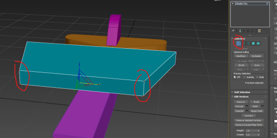
Using the vertex tool I Select these two vertexes at both edges, then I use the scale tool to bring them together. This is easier than using the connect tool to add slices.
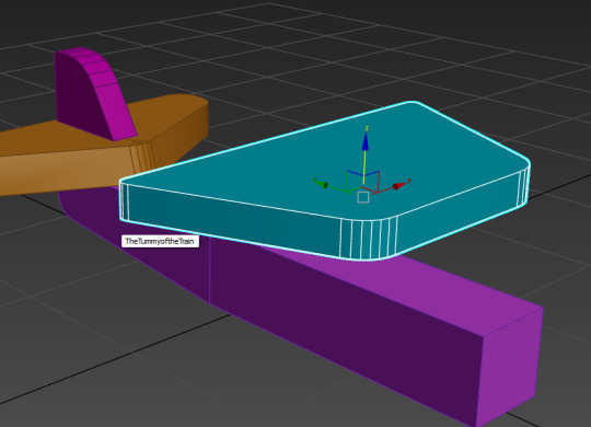
Now I have used chamfer on these edges.

To open the grid and snap settings, right click snaps, then enable axis constraints.

untick snap to grid points and then select vertex for object snapping.

To change the pivot go to the hierarchy tab and select affect pivot only.
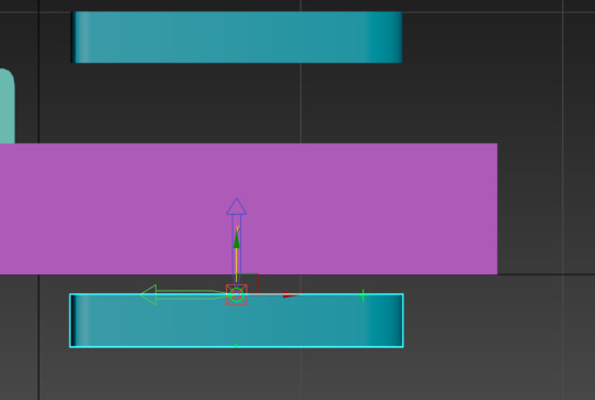
Now snap the pivot to a vertex using the y axis.
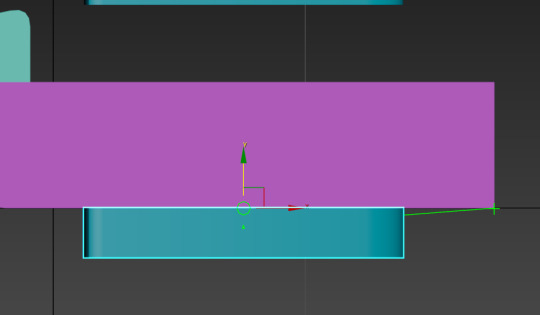
Now move bottom wing to a vertex on the plane body (any) while using the left view (because we only want to move it up and down).

To attach, select one cylinder, then click the attach button, then click on the other cylinders, then deselect and reselect, now they're all connected.

Mirroring is quite monstrous, it might even bring an end to my life. However, the strength to carry on does not come from courage, it comes from the promise of observing such beauty as the Little King John's defeat, then comeback after the great deluge which swept away his lands. Anyway, search for symmetry in the modifier search bar, then go and select mirror, then move the mirrored thing to the left to reveal it. Afterwards select flip, then move the mirrored thing to the right, and set the x to 0.

Giving pants to the plane is not in fact the goal, no, what you're seeing the the default settings of the extrude tool.
Extrude the cylinder off the shape, that is what I did, yes.
Now I use the inset settings to create this wheel. I can add more insets by pressing the plus button next to the tick.
I've created this wheel shape, with slight extrusion of the surface because barely anything is flat, especially tyers.
I cloned the wheel, then I snap rotated the duplicate 180 degrees, then vertex snapped the wheel to a vertex on the other object.
it has been perfected and combined.
0 notes