#circuitbuilding
Text

CAPACITOR 25V 4700uF
STOCK AVAILABLE !!!
FOR PRICE AND MORE INFORMATION FOLLOW US ON OUR WHATSAPP CHANNEL :
For any Query:

Know More: https://www.indiamart.com/rajendra-electronics-newdelhi/
Facebook: https://www.facebook.com/profile.php?id=61550818087962
Instagram: https://www.instagram.com/rajendra.electronic/
LinkedIn: https://www.linkedin.com/in/rajendra-electronics-144b73290/
Reddit: https://www.reddit.com/user/Rajendra_Electronics
Youtube: https://www.youtube.com/@Rajendra_Electronics/about
Twitter: https://twitter.com/Rajendra_Elec
Pinterest: https://in.pinterest.com/rajendraelectronics314/
Tumblr: https://www.tumblr.com/blog/rajendra314
#ElectronicsUpgrade#TechInnovation#capcitortech#diyelectronics#electroniccomponents#TechGadget#capcitorpower#circuitry#diyprojects#electronicrepair#electricalengineering#TechEnthusiast#ElectronicDesign#InnovationInTech#GadgetRepair#circuitbuilding#TechEssentials#powerfulcapacitor#electronicslab#DIYTech
0 notes
Text
5 Relay Module Circuit Designs You Can Build With A Soldering Iron
Introduction
A relay is an electromagnetic switch used to turn on or turn off a circuit. It consists of an electromagnet (a coil of wire that becomes magnetic when current flows through it) and a set of contacts. The electromagnet activates the contacts to either make or break the connection in the circuit. Relay modules are boards that house one or more relays along with the necessary components to control them. In this post, we will show you five different relay module circuit designs that you can build at home with a soldering iron.
Basics of a Relay Module
In order to understand how a relay module works, it is important to know the basics of a relay. A relay is an electrically controlled switch that can be used to turn on or turn off a circuit. A relay module is a device that contains one or more relays.
Relay modules are available in a variety of shapes and sizes, but they all have three basic components: terminals, a coil, and a switch. The terminals are where the electrical connection is made to the load (the device that will be turned on or off by the relay). The coil creates a magnetic field when electricity is flowing through it, and this magnetic field activates the switch. The switch is what actually turns the load on or off.
When choosing a relay module circuit for your project, there are several things to keep in mind. First, you need to decide how many channels you need. One channel can control one circuit, so if you have multiple circuits that you want to control with your relay module, you will need more than one channel. Second, you need to decide what voltage you will be using. Relay modules are available in both low voltage (5V) and high voltage (12V) versions. Finally, you need to decide what type of switching you need: SPDT (single pole double throw) or DPDT (double pole double throw). SPDT modules can only control one circuit at a time, while DPDT modules can control two circuits simultaneously
Types of Relay Modules
There are two main types of relay modules: those with an optocoupler and those without. Optocouplers provide electrical isolation between the control circuit and the load circuit, which can be helpful in preventing voltage spikes and other electrical issues. Relay modules without optocouplers are typically less expensive, but they may not provide the same level of protection against electrical problems.
How to Build a Relay Module Circuit
Building a relay module circuit is not difficult, but it requires some basic understanding of electronics. Here are the steps:
1. gather the necessary components: a soldering iron, solder, wire, a breadboard, and the relay module.
2. Solder two wires to the terminals of the relay module.
3. Connect one end of each wire to the power supply (batteries work fine). The other ends of the wires will be connected to the load (the device you want to control with the relay).
4. Place the relay module on the breadboard so that the wires are not touching each other or any other components. This will prevent shorts.
5. Connect one wire from the power supply to one of the outer legs of the transistor on the relay module (this will be your trigger signal). The other wire from the power supply can go to any other point on the transistor leg or to ground.
6. To test your circuit, apply voltage to the trigger signal wire and observe that current flows through to your load (you may need an ammeter for this). If everything is working properly, you can now build your final circuit on a more permanent medium such as perf board or strip board.
Tips for Building Relay Module Circuits
1. When soldering the relay module to your circuit board, be sure to use a good quality solder. This will ensure that the connection is strong and won't come loose over time.
2. Make sure that the exposed wires on the relay module are insulated. This will prevent them from accidentally touching and shorting out your circuit.
3. If you're using a breadboard to build your circuit, be sure to use long jumper wires to connect the relay module. This will prevent the breadboard from becoming overloaded and causing problems with your circuit.
4. Once you have your circuit built, test it out before connecting it to any power source. This will ensure that everything is working properly and that there are no shorts or other issues that could cause problems down the road.
Conclusion
With a little bit of creativity and a soldering iron, you can build any one of these relay module circuit designs. Each design has its own unique features and benefits, so be sure to choose the one that best suits your needs. And if you're feeling really ambitious, why not try building all five? Explore More
0 notes
Video
instagram
I haven’t made much meaningful progress on my circuit bending projects lately (at least nothing worth sharing) but I’ve been learning a lot by cobbling together some simple circuits out of a bunch of random components. Here are a couple of parallel circuits running off the same battery pack. It ain’t pretty and my soldering is sloppy but I’m really enjoying the process of learning through doing. You got to start somewhere, right? . . . #musicdiscoverylab #lofi #diy #diymusic #maker #makerspace #electronics #soldering #learnasyougo #project #circuitbuilding #circuits #buzzer #leds #battery #workinprogress #beginner #startsimple #babysteps https://www.instagram.com/p/BpaeIcIB1eJ/?utm_source=ig_tumblr_share&igshid=gf73w8atktnr
#musicdiscoverylab#lofi#diy#diymusic#maker#makerspace#electronics#soldering#learnasyougo#project#circuitbuilding#circuits#buzzer#leds#battery#workinprogress#beginner#startsimple#babysteps
0 notes
Photo

#arduino #circuitbuilding day (at Newcastle upon Tyne)
0 notes
Text

Circuitbuilding Do-It-Yourself For Dummies - H. Ward Silver http://dlvr.it/R7nwBP http://dlvr.it/R7nwBP
0 notes
Photo

Is your son or daughter (or you!) ready to level up to breadboarding? Breadboards are used to prototype a circuit design before permanently assembling onto a printed circuit board (PCB). The great thing about breadboards is that if you mess up, you can easily fix the problem and no soldering is required. They are also reusable so they're great for a classroom or group activity. Finally, you can start with basic prototyping and then when ready add an Arduino or other micro controller to program the electronic components. . . . . . #kithub #breadboard #protoboard #breadboarding #circuitdesign #prototype #prototyping #solderless #circuitbuilding #stemeducation #diykit #electronics #electricalengineering #futureengineer #ee
1 note
·
View note
Text
It's Inventors Week!
It’s Inventors Week!
Image courtesy of Discoverycube.org Come to the Discovery Cube OC for a week of tinkering, building, and exploring while learning about electronic and robotic principles. You’ll get to practice your skills and test your knowledge with snap circuit building, Makey Makey invention activities, and an interactive stage show! There will be an exclusive live video conference with NASA on July 7 at…
View On WordPress
0 notes
Text
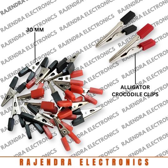
RED & BLACK 30 MM ALLIGATOR CROCODILE CLIPS
STOCK AVAILABLE !!!
FOR PRICE AND MORE INFORMATION FOLLOW US ON OUR WHATSAPP CHANNEL :
For any Query:
☎ : +91-9899391155, +91-9910772484
Know More: https://www.indiamart.com/rajendra-electronics-newdelhi/
Facebook: https://www.facebook.com/profile.php?id=61550818087962
Instagram: https://www.instagram.com/rajendra.electronic/
LinkedIn: https://www.linkedin.com/in/rajendra-electronics-144b73290/
Reddit: https://www.reddit.com/user/Rajendra_Electronics
Youtube: https://www.youtube.com/@Rajendra_Electronics/about
Twitter: https://twitter.com/Rajendra_Elec
Pinterest: https://in.pinterest.com/rajendraelectronics314/
Tumblr: https://www.tumblr.com/blog/rajendra314
#electronicsclip #alligatorclips #diyelectronics #techtools #electricalconnectors #clipcables #redandblack #techaccessories #circuitbuilding #diyprojects #electricalconnections #electronicslab #techgadgets #clipitright #electroniccomponents #TechInnovation #circuitprototyping #makerspace #electronicengineering #diytech
0 notes
Last Seen Blogs

iamthebbwluvr-blog
Untitled

shrdha63
Untitled
shrdha63
Untitled

nico-echo
Kocin

infinitetango
InfiniteTango