#differences between AutoCAD and SOLIDWORKS
Explore tagged Tumblr posts
Visit Tumblr Blog
Explore Tumblr blogs with no restrictions, modern design and the best experience.
Last Seen Tumblr Blogs


Fun Fact
In 2020, 27% of US Tumblr users had an annual household income of over $100,000.
Text
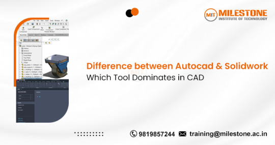
Difference between Autocad and Solidwork: Which Tool Dominates in CAD?
In the realm of Computer-Aided Design (CAD), professionals and enthusiasts alike often find themselves comparing AutoCAD and SolidWorks, two of the most prominent tools available. Both have distinct features and cater to different aspects of design, but the debate on which tool dominates in CAD continues. This blog will delve into the differences between AutoCAD and SolidWorks [Solidworks vs AutoCAD], examining their functionalities, applications, and which tool might be the better choice depending on your needs.
AutoCAD: The Drafting Powerhouse
AutoCAD, developed by Autodesk, is one of the oldest and most widely used CAD software applications. Since its inception in 1982, AutoCAD has become synonymous with 2D and 3D drafting and design. Its extensive use in architecture, engineering, and construction industries highlights its importance in creating detailed drawings and plans.
Key Features:
2D Drafting and Documentation: AutoCAD excels in 2D drafting, providing precise and comprehensive tools for creating detailed floor plans, elevations, and sections.
3D Modeling: While primarily known for 2D, AutoCAD also offers robust 3D modeling capabilities, though it is often considered less intuitive than some specialized 3D CAD software.
Customizability: Users can customize the interface and use AutoLISP for scripting and automation, enhancing productivity.
Industry-Specific Toolsets: AutoCAD provides specialized toolsets for various industries, such as AutoCAD Architecture, AutoCAD Mechanical, and AutoCAD Electrical.
Applications: AutoCAD is widely used in industries that require detailed and accurate drafting. Architects, civil engineers, and urban planners heavily rely on AutoCAD for creating blueprints and detailed construction drawings. Its ability to produce precise 2D documentation makes it indispensable in these fields.
SolidWorks: The 3D Modeling Specialist
SolidWorks, developed by Dassault Systèmes, is renowned for its proficiency in 3D CAD design. Introduced in 1995, SolidWorks quickly gained popularity due to its user-friendly interface and powerful modeling capabilities. It is particularly favored in the mechanical and product design industries.
Key Features:
3D Parametric Modeling: SolidWorks is known for its parametric design approach, allowing users to create complex 3D models that can be easily modified by changing parameters.
Assembly Modeling: Users can design parts individually and then assemble them, checking for interferences and ensuring that all components fit together perfectly.
Simulation and Analysis: SolidWorks offers integrated simulation tools for stress analysis, fluid dynamics, and thermal analysis, enabling designers to validate their models under real-world conditions.
User-Friendly Interface: Its intuitive interface reduces the learning curve, making it accessible to both beginners and experienced users.
Applications: SolidWorks is predominantly used in mechanical engineering, product design, and manufacturing. Its robust 3D modeling and simulation capabilities make it ideal for designing complex machinery, consumer products, and automotive components. Engineers and designers appreciate its ability to visualize and test designs before production, reducing time and costs.
Comparing AutoCAD and SolidWorks
Ease of Use:
AutoCAD: While powerful, AutoCAD's interface can be daunting for beginners, especially in 3D modeling. Mastery requires significant training and experience.
SolidWorks: Known for its user-friendly interface, SolidWorks is easier to learn, particularly for 3D modeling. The intuitive design process is a major advantage.
Functionality:
AutoCAD: Excels in 2D drafting and documentation, making it the go-to tool for architects and civil engineers.
SolidWorks: Superior in 3D modeling and parametric design, ideal for mechanical and product design engineers.
Industry Use:
AutoCAD: Dominates in architecture, construction, and civil engineering due to its precision in 2D drafting.
SolidWorks: Preferred in mechanical engineering, manufacturing, and product design for its advanced 3D modeling and simulation tools.
Cost:
AutoCAD: Generally offers a range of pricing options but can be expensive, particularly for full-featured versions with industry-specific toolsets.
SolidWorks: Also costly, especially with additional simulation and analysis packages, but offers various licensing options to fit different needs.
Which Tool Dominates?
The dominance of AutoCAD or SolidWorks in CAD largely depends on the specific requirements of the project and the industry. AutoCAD remains unparalleled for 2D drafting and documentation, making it indispensable in architecture and construction. On the other hand, SolidWorks leads in 3D modeling and parametric design, making it the preferred choice for mechanical and product design.
Ultimately, the choice between AutoCAD and SolidWorks should be guided by the nature of your work. For those involved in creating detailed 2D plans, AutoCAD is the tool of choice. Conversely, if your focus is on 3D design and simulation, SolidWorks offers unmatched capabilities. Both tools are leaders in their respective areas, and mastering either can significantly enhance your design proficiency.
0 notes
Text
3d design services
In today’s fast-paced and innovation-driven world, 3D design services have become a cornerstone in product development, engineering, architecture, and manufacturing industries. Whether you're conceptualizing a new medical device, prototyping a complex part, or visualizing a final product, 3D design plays a pivotal role in reducing costs and improving efficiency.

One of the key players driving precision and creativity in this field is Foxxtechnologies, a forward-thinking company known for delivering cutting-edge design solutions tailored to meet a wide range of industry needs.
Email Us : [email protected]
What are 3D Design Services?
3D design services involve creating digital three-dimensional models of objects using specialized CAD (Computer-Aided Design) software. These models help visualize the product from all angles and serve as the blueprint for manufacturing, 3D printing, or simulation testing.
These services are widely used in:
Product Development
Medical Devices
Industrial Components
Consumer Electronics
Architecture and Engineering
Why Choose Foxxtechnologies for 3D Design Services?
Foxxtechnologies stands out in the 3D design space due to its experience, technical precision, and client-centric approach. Here’s why they’re a trusted partner in the industry:
1. Industry Expertise
Foxxtechnologies offers deep domain knowledge across sectors such as life sciences, healthcare, and engineering. Their expert team understands regulatory standards and technical challenges, especially in the design of medical devices.
2. Advanced CAD Tools
Using state-of-the-art software like SolidWorks, AutoCAD, and Fusion 360, Foxxtechnologies ensures high-detail accuracy in every project—from concept sketches to final 3D renderings.
3. Customized Solutions
Each project is unique, and so is the design solution. Foxxtechnologies provides custom-tailored 3D modeling services to match your specific project requirements, functionality, and design constraints.
4. Rapid Prototyping Support
With in-house 3D printing capabilities and prototype development services, they help bring digital designs to physical reality quickly and cost-effectively.
5. Compliance-Ready Designs
For industries like biotech and pharmaceuticals, Foxxtechnologies ensures that every 3D design complies with industry regulations, such as ISO 13485 and FDA standards.
Applications of 3D Design by Foxxtechnologies
Medical Devices – Prosthetics, surgical tools, lab components
Industrial Equipment – Machine parts, enclosures, assemblies
Consumer Products – Plastic casings, ergonomic handles
Architectural Models – Building facades, interior mock-ups
Packaging Design – Custom bottles, containers, caps
The Foxxtechnologies Advantage
Partnering with Foxxtechnologies means gaining access to a full-cycle 3D design and development ecosystem. From ideation to production-ready files, their services bridge the gap between imagination and engineering precision.
Conclusion
If you’re looking to bring your next big idea to life, 3D design services are essential—and having a reliable partner like Foxxtechnologies can make all the difference. With a commitment to innovation, precision, and client satisfaction, they continue to shape the future of design across industries.
Email Us : [email protected]
https://www.instagram.com/foxxlifesciencesglobal/
0 notes
Text
Discover the Power of SpaceMouse Pro Wireless for 3D Designers
If you’re a professional in 3D design, architecture, engineering, or animation, then you understand how much your tools affect the quality of your work. The better your tools, the easier it is to create, visualize, and finish your projects. One such tool that’s been making life easier for many designers is the SpaceMouse Pro Wireless by 3Dconnexion.
This isn’t just another mouse. It’s a smart tool that changes how you navigate in 3D space — all with just one hand.
What Makes SpaceMouse Pro Wireless Special?
The SpaceMouse Pro Wireless is not a standard mouse. It’s made for professionals who work with 3D models and need full control over every angle, zoom, and movement. With a unique sensor that allows six degrees of movement (up/down, left/right, forward/backward, and rotation), you get full freedom to move your 3D model naturally.
Instead of constantly dragging your mouse and clicking through commands, you simply push, pull, or twist the controller cap to explore your design smoothly.
Features That Professionals Love
• Smooth 3D control that lets you move and rotate models with one hand • No cables — it connects wirelessly through Bluetooth or USB receiver • Four function keys that you can set to your favorite software shortcuts • Comfortable wrist rest and ergonomic design to reduce hand strain • Comes with a travel case so you can take it wherever you go
Why Wireless is a Game-Changer
The wireless feature isn’t just about avoiding desk clutter — it’s about improving how and where you work. Whether you're switching between home and office or working on-site, the wireless design helps you stay flexible.
• Cleaner workspace without tangled wires • Bluetooth or USB receiver connection options • Long battery life — lasts around 2 months on one charge • One receiver connects multiple 3Dconnexion devices
Works With the Software You Use Every Day
One of the best parts of using SpaceMouse Pro Wireless is that it works with most popular 3D design programs.
• AutoCAD • SolidWorks • Revit • Fusion 360 • Blender • Siemens NX • CATIA • Rhino • SketchUp • Inventor
It also comes with the 3DxWare® 10 software, allowing you to customize the device for different software workflows.
Two Hands, Double the Productivity
The SpaceMouse Pro Wireless doesn’t replace your regular mouse — it works alongside it. Use your dominant hand with a traditional mouse and your non-dominant hand with the SpaceMouse. This two-handed approach gives you more efficiency and comfort while working.
• Better focus by reducing tool switching • Smooth workflow with fewer clicks • Less hand fatigue due to balanced usage • Faster editing and design time
Once you get used to this setup, it’s hard to go back to using only one device.
Ideal for Different Design Professions
The SpaceMouse Pro Wireless fits naturally into many professional roles. Whether you’re modeling, animating, drafting, or reviewing, it gives you better control over your creative process.
• 3D artists can manage camera movements with ease • Engineers can inspect every part of a model from all angles • Architects can take walkthroughs of their building plans • Product designers can fine-tune components without struggle • Students and educators can speed up learning and teaching in CAD tools
It’s an all-rounder that adapts to how you work.
More Than a Device – A Smarter Way to Work
What truly sets the SpaceMouse Pro Wireless apart is how it transforms your daily workflow. It’s not just about moving objects; it’s about making your whole design experience feel easier and more enjoyable.
• You get smoother navigation • You can stay more focused • You reduce stress on your hands • You spend less time dealing with repetitive mouse work
It’s quiet, fast, and strong enough for regular use. Plus, the plug-and-play setup means you don’t have to be a tech expert to get started.
Designed for Professional Comfort
This tool isn’t just smart — it’s also comfortable. The hand rest is soft, and the layout is carefully shaped to support long hours of design work. Whether you're at your desk or on the go, this mouse is built for real work.
And with the included carry case, it’s safe to bring to meetings or remote job sites without worrying about damage.
A Tool That Matches Your Creativity
If you work in design, you need tools that match your creative energy. The SpaceMouse Pro Wireless helps you feel like you’re “inside” your model — rotating, exploring, and understanding every part from any angle.
It removes limits. It adds flexibility. And most of all, it helps you do better work without adding stress.
Time to Upgrade How You Work?
Whether you're just starting in 3D design or you’ve been in the industry for years, the SpaceMouse Pro Wireless is a game-changer. It’s designed to work the way you think — fluid, simple, and smart.
• Work faster • Stay comfortable • Create more freely
This is the tool your workflow has been missing. Give it a try and see how much more enjoyable your workday can be.
0 notes
Text
Career-Focused Courses for Mechanical Design Engineers in Chennai
Introduction
Are you passionate about creating mechanical components and systems that actually work in the real world? If yes, then stepping into the world of mechanical design might be the perfect path for you. And if you're in or around Tamil Nadu, joining a mechanical design course in Chennai is a solid way to build your future.
Whether you're a recent graduate or an engineer looking to upskill, Chennai offers a variety of training programs that blend theory, tools, and hands-on practice.

Why Consider Mechanical Design Courses in Chennai?
Chennai is more than just a manufacturing and automobile hub — it's also home to some of the best technical training centers in India. These institutes offer comprehensive mechanical design training courses in Chennai that go beyond books and lectures.
Expect to work with industry-grade tools like:
AutoCAD
SolidWorks
CATIA
ANSYS
GD&T systems
From understanding basic drafting to mastering complex 3D models, these courses cover it all.
What Will You Learn?
If you're looking for in-depth and practical knowledge, explore various mechanical engineering design courses in Chennai that focus on:
Design principles for real-world applications
Reading and creating engineering drawings
Strength of materials and design calculations
Software-based simulations and analysis
Prototyping and design documentation
These courses are designed to prepare you for everything from product development to system-level design in industries like automotive, aerospace, manufacturing, and heavy machinery.
Who Should Enroll?
If you’re wondering whether this is right for you, here’s a quick checklist.The following reasons make these mechanical design engineering courses in Chennai perfect:
Mechanical engineering students
Recent graduates aiming for core jobs
Working professionals looking to specialize in design
Engineers shifting from production to design roles
No matter where you are in your career, these programs help bridge the gap between theoretical education and real-time industry expectations.
Hands-On Experience That Makes a Difference
One thing that really stands out about the mechanical design training courses in Chennai is the emphasis on project-based learning. You won’t just be sitting in front of a screen — you’ll be working on actual projects that mimic real industry challenges.
Live projects, design reviews, and case studies make these courses far more engaging and practical than standard classroom programs.
Final Thoughts
Mechanical design is more than just lines on a screen — it’s the art and science of bringing ideas to life. By enrolling in a mechanical design course in Chennai, you gain the tools, knowledge, and confidence to enter a career that’s both creative and technically rewarding.
Whether you're targeting your first job or climbing the professional ladder, Chennai's engineering design programs are built to help you succeed.
##Seleniumtraininginchennai#Seleniumcourseinchennai#Seleniumcoursechennai#Seleniumtraininginstituteinchennai#SeleniumTrainingfees#Seleniumtraining#Seleniumcourse#Seleniumtraininginstitute
0 notes
Text
How to Make Utility Patent Drawings That Meet USPTO Standards | The Patent Experts
Creating accurate and USPTO-compliant utility patent drawings is essential to filing a successful utility patent application. These drawings are not just visual aids — they are legal documents that explain your invention in detail. Without proper illustrations, your application may be delayed, rejected, or misunderstood by the examiner.

This guide will walk you through everything you need to know about making utility patent drawings — from understanding USPTO requirements to choosing the right tools and avoiding common mistakes. We’ll also explore examples, FAQs, and real-life case studies to illustrate the process.
Why Are Utility Patent Drawings Important?
Utility patent drawings serve as a visual explanation of your invention. They clarify what words alone often can’t. The USPTO requires that every element of the invention described in the claims must also appear in the drawings.
Drawings:
Support the claims made in the application
Help examiners understand complex structures
Prevent ambiguity and misinterpretation
Are legally binding and used in enforcement
Even if the invention seems simple, clear drawings can mean the difference between approval and rejection.
USPTO Utility Patent Drawing Requirements
The USPTO outlines strict guidelines for utility patent drawings. Failing to comply with these can result in office actions and rework. Here’s what the USPTO expects:
Black and White Line Art: Color drawings are only accepted if color is essential to understanding the invention and if a petition is filed.
Size and Margins: 8.5 x 11-inch pages with specific margins (top: 1", left: 1", right: 0.6", bottom: 0.4").
Readable and Uniform: Drawings must be clean, sharp, and to scale.
No Text Inside Drawings: Only reference numbers are allowed.
Consistent Line Styles: Solid lines for visible parts, dashed or broken lines for hidden or optional parts.
Proper Labeling: All parts must be numbered and consistent throughout views.
Choosing the Right Views for Your Invention
The goal of utility drawings is to represent the invention from all necessary perspectives. Depending on the complexity of your design, use a combination of the following:
Front View — Shows the most characteristic side.
Side and Rear Views — Offer additional dimensional context.
Top and Bottom Views — Clarify structure and orientation.
Sectional Views — Reveal internal structures or mechanisms.
Exploded Views — Show how parts fit and interact.
Perspective View (Optional) — Useful for complex geometries.
Each view must be aligned and proportionally accurate. Use multiple sheets if required to ensure every detail is visible and understandable.
Best Practices for Line Work and Labeling
Line styles must convey information clearly and meet legal requirements:
Solid Lines: Represent claimed, visible parts.
Broken Lines: Represent environment, optional parts, or elements not claimed.
Hatching: Used for sectional views to show material or distinguish parts.
Labeling must be:
Done using numerals (e.g., 100, 110, 120…)
Clear and legible
Matched exactly with descriptions in the specification
Avoid labeling elements with letters or descriptive words. Consistency is crucial.
Tools and Software for Creating Utility Drawings
While hand-drawing is technically acceptable, digital tools offer precision and efficiency. Here are popular tools for professional utility patent drawings:
AutoCAD — Industry standard for 2D technical drawings.
SolidWorks — Ideal for mechanical inventions and 3D modeling.
CorelDRAW — Great for vector-based illustrations.
Adobe Illustrator — Useful for clean, high-resolution line art.
SketchUp — Quick 3D concept design with export options.
Many inventors hire professional illustrators who specialize in USPTO-compliant drawings to avoid mistakes and save time.
Common Mistakes to Avoid
Getting drawings wrong can cost you valuable time and money. Here are common pitfalls:
Using color without approval
Including text inside drawings
Not showing all claimed elements
Poor resolution or pixelated lines
Repeating reference numbers for different elements
Incorrect or missing views
Not following required margins and page sizes
Tip: Review the USPTO’s Manual of Patent Examining Procedure (MPEP), Chapter 608.02 for drawing guidelines.
Real-Life Example: Smart Bottle Invention
An inventor designed a smart water bottle that tracks hydration. The utility patent drawings included:
Side view showing the bottle’s shape
Sectional view of the cap with embedded sensors
Exploded view showing the battery, chip, and housing
Perspective view to give an overview of the design
Each part was labeled and described in the written specification. The examiner immediately understood the invention’s structure, resulting in a faster approval process.
Case Study: When Bad Drawings Delay a Patent
A startup submitted a patent for a foldable bicycle. Their drawings were hand-sketched, lacked consistency, and had no reference numbers. The USPTO issued an office action requesting corrected drawings.
They then hired a professional illustrator, who:
Redrew all views to scale using CAD
Added correct labels and line styles
Submitted compliant PDF files
The revised submission passed examination, but the delay cost them 5 months and several hundred dollars in rework.
Advanced Tip: Use Flow Diagrams for Method-Based Inventions
If your invention involves a process or method, consider adding flow diagrams. These are not always required but can:
Clarify how steps relate
Support software or business method claims
Help the examiner visualize functionality
Label each step and make sure it aligns with your written claims.
Frequently Asked Questions
Q1: Do I need to submit utility patent drawings with my provisional patent application? A: No, it’s not mandatory, but it’s highly recommended. Well-prepared drawings strengthen your filing and establish early disclosure.
Q2: Can I draw them myself? A: Yes, but unless you’re trained in technical drawing, mistakes are likely. It’s safer to use software or hire a professional.
Q3: Do I need to include every part of my invention? A: Yes. Every part you describe or claim must appear in the drawings. Omitting elements may weaken your application.
Q4: Are color drawings ever acceptable? A: Only if color is essential to understanding the invention. You must submit a petition and justification.
Q5: How many views should I include? A: Enough to fully disclose the invention. At least front, side, and top views are typical. More complex inventions require sectional and exploded views.
Q6: Can I use photos instead of drawings? A: Only in rare cases and with special approval. The USPTO generally requires line drawings for clarity and legal purposes.
Q7: Will professional drawings increase my approval chances? A: Absolutely. They reduce ambiguity, ensure compliance, and speed up the examination process.
Final Thoughts
Utility patent drawings are a non-negotiable part of the patent application process. They communicate your invention visually and play a critical role in approval. Whether your invention is simple or complex, investing in proper, USPTO-compliant illustrations is one of the smartest steps you can take.
Get USPTO-Compliant Utility Patent Drawings from Experts
Ready to protect your invention with professional, fully compliant patent drawings? Don’t risk costly delays or office actions.
Get started with The Patent Experts now and ensure your drawings meet every USPTO requirement.
#utility patent illustration services#utility patent drawings#patent illustrations#patent drawings#uspto#patent application#patent drafting#utility patent drawing requirements#utility patent drawing examples#uspto patent drawings#utility patent filing#patent line drawings#black and white patent drawings#detailed patent illustrations#invention drawings#technical patent drawings
0 notes
Text

Top 5 Best CAD Software for Mechanical Design in 2025
Introduction
In the world of mechanical engineering, designing accurate, functional, and reliable components is critical. This is where CAD (Computer-Aided Design) software comes into play. CAD tools help engineers create, modify, analyze, and optimize mechanical designs with precision and efficiency.
With dozens of software options available, selecting the right CAD software can be challenging. Whether you're a student, a beginner, or a professional mechanical designer, this guide highlights the Top 5 Best CAD Software for Mechanical Design in 2024 to help you make the right choice.
1. AutoCAD
Overview:
Developed by Autodesk, AutoCAD has been a staple in the engineering and architecture industries for decades. It is widely used for 2D drafting and 3D modeling.
Key Features:
Precision drawing tools
Extensive library of mechanical components
Easy collaboration and documentation
Widely supported file formats
Best For:
Mechanical engineers and drafters who need detailed 2D/3D design capabilities.
2. SolidWorks
Overview:
SolidWorks, developed by Dassault Systèmes, is a parametric CAD tool that is highly favored for mechanical part and assembly design. It offers powerful simulation tools and an intuitive interface.
Key Features:
3D modeling with real-time simulation
Assembly modeling and motion analysis
Built-in design automation
Excellent for product development and prototyping
Best For:
Mechanical designers working with assemblies, simulations, and custom product development.
3. CATIA
Overview:
CATIA (Computer-Aided Three-dimensional Interactive Application) is another powerful tool from Dassault Systèmes, mainly used in the aerospace and automotive industries for complex product designs.
Key Features:
Advanced surface modeling and multi-disciplinary design
Seamless collaboration between teams
Integration with PLM (Product Lifecycle Management) tools
High-level system engineering support
Best For:
Large-scale industrial mechanical design, especially in high-end industries like aerospace.
4. Creo (formerly Pro/ENGINEER)
Overview:
Creo, developed by PTC, is known for its robust feature set covering everything from conceptual design to product simulation. It supports parametric and direct modeling.
Key Features:
Real-time simulation and analysis
AR (Augmented Reality) design visualization
Detailed sheet metal and plastic part design
Scalability across different stages of design
Best For:
Advanced mechanical engineering applications and enterprise-level product design.
5. Fusion 360
Overview:
Fusion 360 is a cloud-based CAD/CAM/CAE software from Autodesk. It’s beginner-friendly and widely used for product development, 3D printing, and CNC manufacturing.
Key Features:
Unified platform for CAD, CAM, and CAE
Cloud-based collaboration and file access
Free for students, startups, and hobbyists
Integrated simulation and generative design
Best For:
Startups, students, and small teams looking for a versatile and budget-friendly solution.
Conclusion
Choosing the right CAD software depends on your project requirements, industry standards, and level of expertise. Whether you're designing complex machinery or prototyping small components, these tools can transform your ideas into high-precision models.
From AutoCAD’s 2D/3D drafting to Fusion 360’s all-in-one cloud platform, each software brings unique strengths to the table. Mastering any of them can significantly boost your career in mechanical design.
#CAD Software 2025#Best CAD for Mechanical Design#3D CAD Tools#Engineering Design Software#Mechanical Design CAD#Top CAD Software 2025
0 notes
Text
Patent Drawings for Beginners: A Comprehensive Step-by-Step Guide
If you're preparing to file a patent for the first time, you're probably focused on the invention itself: the functionality, the uniqueness, the market opportunity. But there’s one critical component that can make or break your application — patent drawings.
Many beginners underestimate the importance of clear, accurate, and professionally prepared patent drawings. Yet, drawings are often required by patent offices (like the USPTO), and even when optional, they significantly strengthen your filing.
In this guide, we’ll walk you through everything you need to know about patent drawings, step-by-step — from what they are, to how to create them, to common mistakes to avoid.
What Are Patent Drawings?
Patent drawings are illustrations included in a patent application to help describe and explain the invention.
They can show:
How the invention looks (in design patents)
How it works or how it’s structured (in utility patents)
How components interact
How a process or method flows
Good patent drawings make it easier for a patent examiner to understand the invention quickly, helping your chances of getting your patent approved.
Types of Patents That Need Drawings
You’ll generally need drawings for two main types of patents:
Utility Patents (protect functionality and structure)
Mechanical devices
Electronic circuits
Chemical compositions
Software process flowcharts
Design Patents (protect appearance and ornamentation)
Consumer products
Furniture
Packaging
Apparel designs
In a utility patent, drawings support the technical description. In a design patent, drawings are the primary claim — they define exactly what the design looks like.
Why Patent Drawings Are Important
Patent drawings are more than just pretty pictures. They serve crucial purposes:
Clarify complex inventions: Visuals can explain better than text.
Strengthen your claims: Proper drawings show you’ve fully "possessed" the invention.
Speed up approval: Examiners spend less time guessing what you mean.
Avoid rejections: Missing drawings can lead to objections or extra costs later.
Defend your patent rights: Good drawings support enforcement if your patent is challenged.
Step-by-Step Guide to Creating Patent Drawings
Let’s dive into the process for beginners:
Step 1: Understand Drawing Requirements
Before you begin creating patent drawings, it’s important to know what the patent office expects. For the USPTO, the basic requirements include:
Black-and-white line drawings — Color is not allowed unless specifically authorized
Clear, dark, uniform lines — No smudging, shading (unless to show contours), or irregularities
Proper margins — Typically 1 inch on the top and left, 3/8 inch on the right and bottom.
Consistent labeling — Use reference numbers clearly and match them with the written description.
Multiple views — Include front, side, top, and perspective views to fully depict the invention.
No unnecessary shading — Only include shading to indicate surface contours or shape.
Pro Tip: Every element mentioned in the description must appear in the drawings—and every drawing feature should be covered in the description. Consistency prevents costly rejections.
Step 2: Gather Your Tools
For beginners, you have two basic options:
Hand drawings: Fine for concept sketches, but must be extremely clean and professional if submitted.
Computer-aided design (CAD): Software like AutoCAD, SolidWorks, or even Adobe Illustrator can create precise drawings.
Most professionals use CAD software because it ensures precision and easy edits.
Step 3: Choose the Right Views
To fully disclose your invention, you must include enough views to show every aspect. The required views differ between Utility Patents and Design Patents:
For Utility Patents, you should include:
Perspective view (optional but helpful to show 3D aspects)
Front view
Rear view
Right side view
Left side view
Top view
Bottom view
Sectional views (cutaways to show internal details)
Flowcharts (for process-related inventions)
For Design Patents, multiple views are mandatory to fully capture every visible part of the design:
Front, Rear, Left, Right, Top, and Bottom views
Perspective view (highly recommended for clarity)
Remember: If two sides (e.g., left and right) are identical, you can state this in the specification instead of including a separate drawing for each side.
Proper labeling is crucial for ensuring clarity and consistency between the drawings and the written specification. Here’s how to do it effectively:
Use reference numbers to label each part of the invention clearly.
Example:
101 = Handle
102 = Body
103 = Switch
Consistency is key. Ensure that the reference numbers are used consistently across all views and in the written description.
Label all important elements of the invention, including those that are essential for understanding the functionality and structure.
Why it’s important:
Reference numbers connect specific parts of the drawing to corresponding descriptions in the patent application, making it easier for examiners and others to understand your invention.
Step 5: Use Solid and Broken Lines Properly
Solid lines show what you’re claiming as part of the invention
Broken (dashed) lines show unclaimed parts or environment
This distinction is especially important in design patents to limit your claim to specific parts.
Step 6: Add Necessary Shading
Shading shows surface contours like curves or indentations. Without shading, your invention could appear flat and two-dimensional — which might weaken your claims.
Use shading:
To illustrate 3D aspects (e.g., domed vs flat surfaces)
To differentiate materials if necessary
But avoid overdoing it; too much shading can clutter the drawing.
Step 7: Format Properly
After drawing, make sure your figures are properly organized:
Each figure (view) should be numbered (e.g., FIG. 1, FIG. 2)
Consistent font size (usually simple block letters)
Match margins, line weights, and numbering standards
Each page should be neat, professional, and easy to read.
Step 8: Review and Correct
Before you submit, triple-check:
Are all views complete?
Are reference numbers consistent?
Is everything necessary included?
Is there anything that could confuse the examiner?
Do drawings comply with USPTO or PCT standards?
Mistakes cause delays, extra costs, and even possible rejection.
Consider having a patent professional or patent drawing expert review your work.
Common Beginner Mistakes to Avoid
When creating patent drawings, even small errors can lead to rejections or delays. Avoid these common mistakes:
Inconsistent views: Ensure all views (e.g., front, side, top) show consistent shapes and proportions.
Sloppy line work: Use clean, smooth lines. Avoid wavy, smudged, or pixelated lines that can hinder clarity.
Omitting critical parts: Double-check that every element described in the specification is included in the drawings.
Poor labeling or missing reference numbers: Label parts clearly and consistently, and ensure reference numbers are used throughout.
Improper scaling: Ensure the proportions are correct and consistent across all views. Elements should be in proper relation to each other.
Submitting low-resolution scans: Always submit high-quality, clear drawings. Low-resolution images can blur important details.
Forgetting shading for 3D features: Use appropriate shading to indicate the depth and surface contours of 3D elements.
Wrong file formats: Ensure you're submitting the correct file format (usually PDFs) as per USPTO requirements. Avoid using JPEGs.
When to Hire a Professional Patent Drawing Service
For simple inventions, you might create drawings yourself if you have the skills. However, for complex mechanical, electrical, biotech, or detailed designs, it’s highly recommended to use a professional patent drawing service.
Benefits of hiring professionals:
Full compliance with patent office standards
Faster production and revisions
Higher chance of first-round approval
Better presentation if you ever need to enforce your patent in court
The cost is minor compared to the potential losses from a rejected or unenforceable patent.
Conclusion
Patent drawings aren’t just an afterthought — they are a core part of a successful patent application. Done correctly, they can make the difference between a smooth approval and a frustrating, costly rejection.
By following this step-by-step guide, beginners can confidently approach the patent drawing process — and ensure that their invention is presented clearly, accurately, and professionally.
Remember: in patents, details matter — and your drawings are the language that brings your invention to life.
If you need help, don’t hesitate to consult with a professional patent drawing service to perfect your submission and boost your chances of success!
0 notes
Text
The Art and Science of Designing in Mechanical and Civil Engineering
Design is the heart of engineering. Whether you are constructing a towering skyscraper or building a precision machine, the first and most critical step is a well-thought-out design. Mechanical engineering design and civil engineering design both demand creativity, technical knowledge, and a solid understanding of materials, forces, and human needs. In today's competitive world, mastering design isn't just an advantage—it's a necessity. In this blog we will talk about every aspect of Mechanical/Civil Engineering Design.
What is Mechanical Engineering Design?
Mechanical engineering design involves the creation and development of mechanical systems, machines, and tools. It is a meticulous process that blends science, mathematics, and aesthetics to bring a product to life. From a tiny gear inside a wristwatch to a massive jet engine, mechanical engineers are responsible for ensuring that their designs are functional, efficient, durable, and safe.
The journey of product design in mechanical engineering usually begins with an idea, often inspired by a need in society. This idea is transformed into sketches, technical drawings, and eventually, detailed 3D models. Modern engineers heavily rely on CAD tools for engineers like AutoCAD, SolidWorks, and CATIA to speed up the design process and improve accuracy.
Mechanical design isn't just about innovation; it’s about problem-solving. Engineers must consider factors such as material strength, thermal effects, environmental conditions, manufacturing feasibility, and cost-effectiveness when designing a product.
What is Civil Engineering Design?
On the other side, civil engineering design focuses on the planning, analysis, and construction of infrastructure projects like bridges, buildings, highways, and water systems. The responsibility is massive—civil engineers design the structures that shape our cities and communities.
The process of structural design in civil engineering ensures that structures can withstand both everyday use and extreme events like earthquakes or hurricanes. Civil engineers must master the art of balancing safety, aesthetics, function, and budget.
Software like Revit, STAAD Pro, and ETABS are crucial in today’s civil engineering world, enabling engineers to create realistic models and perform structural analysis more efficiently.
The Importance of Design in Engineering
The importance of design in engineering cannot be overstated. Good design minimizes costs, maximizes performance, and ensures safety and sustainability. Poor design, on the other hand, can lead to catastrophic failures, financial losses, and even loss of life.
In both mechanical and civil engineering, a thoughtful design process involves:
Understanding the user requirements
Conducting thorough research
Selecting appropriate materials
Analyzing loads and stresses
Iterative prototyping and testing
Optimization for performance and cost
Design acts as the blueprint for success. Without a solid design, even the best ideas can crumble during execution.
Key Differences Between Mechanical and Civil Design
While there are similarities in the design thinking of mechanical and civil engineers, there are fundamental differences:
Mechanical engineering design usually deals with moving parts and dynamic systems.
Civil engineering design often focuses on static structures and geotechnical concerns.
Tolerances in mechanical design are often microscopic, while civil design deals with large scales but must account for broader factors like soil behavior and environmental impact.
Mechanical designs often have shorter life cycles (machines get upgraded or replaced frequently), whereas civil structures are built to last decades, even centuries.
Understanding these differences is crucial for young engineers choosing their career paths.

Best Practices in Engineering Design
Whether you are designing a new product or a suspension bridge, there are some best practices in engineering design that can guide your work:
Start with Clear Objectives: Know what problem you are solving and what success looks like.
Prioritize Safety: Always design with safety as a top priority.
Use Advanced Tools: Invest time in mastering CAD tools for engineers; they improve efficiency and precision.
Incorporate Sustainability: Modern designs must consider environmental impacts.
Iterate Constantly: The first design is rarely the best. Iterate based on simulations, prototyping, and testing.
Collaborate Across Disciplines: Complex designs often require input from specialists in other fields.
Stay Updated: Engineering evolves quickly. Keep learning about new materials, methods, and technologies.
By following these practices, engineers can create designs that are not just functional, but truly outstanding.
The Role of Technology in Modern Design
The influence of technology on engineering design is transformative. CAD software, 3D printing, AI-driven simulations, and even VR models allow engineers to visualize, test, and refine their designs like never before.
In mechanical engineering design, 3D printing enables rapid prototyping, helping designers to test concepts quickly and cost-effectively. Similarly, in civil engineering design, Building Information Modeling (BIM) provides a detailed and collaborative approach to large-scale projects.
These technologies not only improve design accuracy but also enhance communication among stakeholders, reducing the risk of costly misunderstandings.
Conclusion
Design is where imagination meets practicality. In both mechanical and civil engineering, it is the silent architect behind every innovation and structure. Engineers who master the principles of design—and who understand the tools, materials, and human factors involved—position themselves for a successful and impactful career.Whether you are passionate about building machines that change the world or structures that stand the test of time, focusing on best practices in engineering design will be your greatest asset. The future belongs to those who can design it well.
1 note
·
View note
Text
Get Industry-Ready with a Summer Training Course for Engineering Students
Summer break is often seen as a time to relax — but for engineering students with big dreams, it's also a golden opportunity to grow. A Summer Training Course is more than just a short-term program — it’s a career investment that bridges the gap between academic knowledge and real-world application.
In today’s fast-paced tech-driven world, employers look for more than degrees. They want skills, hands-on experience, and innovative thinking — exactly what a quality summer training course offers.
What is a Summer Training Course?
A Summer Training Course is a specialized, practical program designed to help engineering students gain exposure to real-time projects, tools, and technologies. Conducted during the summer break, these courses usually run for 4–6 weeks and are focused on skill-building, project development, and industry orientation.
Whether you're from mechanical, computer science, electronics, or civil engineering — there's a summer course tailored just for your domain.
Why Choose a Summer Training Course?
🌟 Skill Development That Matters
Courses are designed to teach job-ready skills — like coding, designing, simulation, automation, and analytics — in a structured and easy-to-follow way.
🌟 Project-Based Learning
You won’t just learn — you’ll build. Most summer training courses include hands-on projects that let you apply what you've learned to solve real-world problems.
🌟 Get Certified
After successful completion, students receive a certificate that adds value to their resume and improves placement opportunities.
🌟 Explore Career Paths
A Summer Training Course allows you to explore different technical domains — so you can discover what truly excites you before making long-term career decisions.
Top Domains Covered in Summer Training Courses
Python Programming & Machine Learning
Full-Stack Web Development
Internet of Things (IoT)
Robotics and Embedded Systems
AutoCAD, SolidWorks for Mechanical Engineers
Cloud Computing & Cybersecurity
Mobile App Development
Data Science & Big Data Analytics
Who Should Enroll in a Summer Training Course?
1st to final-year engineering students
Diploma holders in technical fields
Students preparing for internships and placements
Anyone eager to enhance technical skills in a short span
Final Thoughts
If you're serious about shaping your engineering career, don’t let this summer go to waste. A Summer Training Course can help you transform from a student into a skilled professional — ready to face real-world challenges with confidence.
So this summer, swap your break for a breakthrough — enroll in a summer training course and take the first step toward a brighter, smarter future.
0 notes
Text
Excellence Technology: A Premier Hub for IT Training and Development
Introduction
In today's rapidly evolving digital world, acquiring the right technical skills is essential for career growth and success. Excellence Technology, a leading software development and industrial training company, stands out as a premier institution offering top-tier training programs in Chandigarh and Mohali. With an ISO 9001:2015 and MSME certification, the institute provides a wide range of courses designed to equip students and professionals with the latest industry knowledge and practical experience. This article delves deep into the various aspects of Excellence Technology, including its training programs, unique features, industry relevance, and how it contributes to shaping the future of IT professionals.
A Legacy of Excellence in IT Training
Excellence Technology has built a strong reputation for providing high-quality education and professional training to students across various domains. The institute is dedicated to bridging the gap between academic learning and industry requirements by offering hands-on training that ensures employability and career advancement. Over the years, the institute has successfully trained thousands of students, helping them secure lucrative job opportunities in top IT firms.
Wide Range of Courses
Excellence Technology offers a diverse array of courses catering to different aspects of the IT and digital world. These courses are tailored to meet the demands of students, job seekers, and professionals looking to enhance their skills. Some of the key training programs include:
1. Industrial Training Programs
The institute provides six-week and six-month industrial training programs in multiple disciplines. These programs are ideal for students pursuing B.Tech, MCA, BCA, and other technical courses who wish to gain hands-on experience in their respective fields. The training covers:
Web Development
Mobile App Development
Digital Marketing
Machine Learning & AI
Cyber Security
Networking and Hardware
2. Full-Stack Web Development
For those looking to become proficient in web development, the Full-Stack Web Development course at Excellence Technology offers training in:
HTML, CSS, and JavaScript
ReactJS and Angular
Node.js and Express.js
MongoDB and MySQL
RESTful API Development
This course equips students with the skills needed to build dynamic and responsive websites and web applications.
3. Java Training
Java remains one of the most popular programming languages, and Excellence Technology provides an extensive Java training program that includes:
Core Java
Advanced Java
Spring Framework
Hibernate
Web Services
With a strong focus on practical learning, students gain proficiency in Java development, which is highly sought after in the software industry.
4. Digital Marketing Course
With businesses shifting online, digital marketing has become a crucial skill. Excellence Technology offers an in-depth digital marketing course that covers:
SEO (Search Engine Optimization)
PPC (Pay-Per-Click Advertising)
Social Media Marketing
Email Marketing
Content Marketing
Google Ads and Analytics
The course is designed to help individuals and businesses enhance their online presence and drive engagement through strategic marketing techniques.
5. Mechanical & Civil Engineering Training
Excellence Technology extends its expertise to engineering students by offering specialized training in mechanical and civil engineering. This includes:
AutoCAD
SolidWorks
3D Modeling
Structural Analysis
Revit Architecture
These programs provide students with practical exposure to real-world engineering challenges.
Unique Features of Excellence Technology
Several factors set Excellence Technology apart from other training institutes:
1. Experienced Faculty
The institute boasts a team of highly qualified and industry-experienced trainers who guide students through comprehensive learning modules. They provide mentorship and support to ensure students grasp complex concepts effectively.
2. Hands-on Training Approach
Excellence Technology follows a project-based learning approach, ensuring students gain practical experience. Live projects and real-world case studies help them apply their knowledge effectively.
3. Industry-Oriented Curriculum
The courses are designed in alignment with industry trends and demands. Regular updates ensure that students learn the latest technologies and frameworks, making them job-ready.
4. Certification and Placement Assistance
Upon completion of a course, students receive industry-recognized certifications, enhancing their credibility. Additionally, the institute provides placement assistance by connecting students with top companies and startups.
5. Flexible Learning Options
To cater to diverse learners, the institute offers both classroom and online training programs. This flexibility allows working professionals and students to upskill at their convenience.
Industry Relevance and Job Opportunities
Excellence Technology has strong industry connections, enabling students to access numerous job opportunities upon completing their training. The institute collaborates with top IT companies, ensuring students get placed in reputed firms with competitive salary packages.
Many alumni have successfully transitioned into roles such as:
Software Developers
Web Designers
Digital Marketing Specialists
Cyber Security Analysts
Network Engineers
Data Scientists
Testimonials from Students
The success stories of students reflect the effectiveness of the training programs at Excellence Technology. Many students have shared positive feedback, highlighting how the institute helped them gain confidence, develop technical skills, and secure well-paying jobs.
Conclusion
Excellence Technology is more than just a training institute—it is a gateway to a successful career in the IT industry. With its industry-aligned courses, expert trainers, hands-on learning approach, and strong placement support, the institute empowers students to achieve their professional goals. Whether you are a student looking to enhance your technical skills or a professional aiming for career growth, Excellence Technology provides the perfect platform to build a rewarding future.
For those aspiring to excel in the world of technology, enrolling in Excellence Technology’s courses is a step in the right direction.
0 notes
Text
Patent Drawing Sheet Size Requirements: Navigating Global Patent Office Standards

Patent drawings are the visual backbone of any patent application, and understanding the precise sheet size requirements can mean the difference between a smooth application process and frustrating rejections. Different patent offices worldwide have specific guidelines that inventors and patent professionals must carefully follow to ensure compliance.
Utility and Design Patent Drawing Starting @$28 per view. Order Now
View Our Work Samples
Global Patent Office Sheet Size Standards
United States Patent and Trademark Office (USPTO)
Acceptable Sizes:
US Letter (8.5 × 11 inches)
A4 (210 × 297 mm)
Preferred Format: US Letter for domestic applications
Margin Requirements:
Top: 2.5 cm
Left: 2.5 cm
Right: 1.5 cm
Bottom: 1 cm
World Intellectual Property Organization (WIPO)
Mandatory Size: A4 (210 × 297 mm)
Strict Adherence: No alternative sizes accepted for international (PCT) applications
Consistent Global Standard: Most international patent offices follow WIPO guidelines
Key Considerations for Sheet Size Selection
Factors Influencing Sheet Size Choice
Patent filing jurisdiction
Type of patent application (utility, design, plant)
Complexity of technical illustrations
Reproduction and scanning requirements
Specific Requirements by Patent Type
Utility Patents: Multiple views may require careful layout planning
Design Patents: Consistent scaling across all standard views
Plant Patents: Sometimes allow color drawings or photographs
Common Mistakes to Avoid
Using non-standard paper sizes
Incorrect margin measurements
Inconsistent scaling across drawings
Inadequate white space around illustrations
Best Practices for Sheet Size Compliance
Always confirm current requirements with specific patent office
Use professional drafting software with built-in templates
Maintain consistent drawing quality across all sheets
Ensure clear, reproducible line work within specified margins
International Filing Considerations
For PCT (Patent Cooperation Treaty) applications, A4 is the universal standard
Some countries may have slight variations in margin requirements
Digital submissions increasingly supporting standardized formats
Tools and Resources
Recommended Drafting Software:
AutoCAD
Adobe Illustrator
SolidWorks
Visio
Online resources from USPTO and WIPO for current guidelines
Conclusion: Precision Matters
Navigating the intricate world of patent drawing requirements can seem daunting, but meticulous attention to detail – especially sheet size and formatting – is crucial. By understanding and implementing these guidelines, inventors can significantly improve their chances of a successful patent application.
Remember, a well-prepared patent drawing is not just a technical requirement; it's a powerful tool for clearly communicating your innovative ideas to patent examiners and protecting your intellectual property.
About PatDraw
With over two decades of experience, PatDraw team has completed thousands of utility and design drawings for a wide range of clients worldwide.
#design patent#legal services#patent drawing services#patentportfolio#inventions and patents#patent drawings#utility patent drawings#Design patent drawings#patent drawings company#perfect patent drawings#draw you ideas#patsketch
0 notes
Text
3d design services
In today’s fast-paced and innovation-driven world, 3D design services have become a cornerstone in product development, engineering, architecture, and manufacturing industries. Whether you're conceptualizing a new medical device, prototyping a complex part, or visualizing a final product, 3D design plays a pivotal role in reducing costs and improving efficiency.

One of the key players driving precision and creativity in this field is Foxxtechnologies, a forward-thinking company known for delivering cutting-edge design solutions tailored to meet a wide range of industry needs.
Email Us : [email protected]
What are 3D Design Services?
3D design services involve creating digital three-dimensional models of objects using specialized CAD (Computer-Aided Design) software. These models help visualize the product from all angles and serve as the blueprint for manufacturing, 3D printing, or simulation testing.
These services are widely used in:
Product Development
Medical Devices
Industrial Components
Consumer Electronics
Architecture and Engineering
Why Choose Foxxtechnologies for 3D Design Services?
Foxxtechnologies stands out in the 3D design space due to its experience, technical precision, and client-centric approach. Here’s why they’re a trusted partner in the industry:
1. Industry Expertise
Foxxtechnologies offers deep domain knowledge across sectors such as life sciences, healthcare, and engineering. Their expert team understands regulatory standards and technical challenges, especially in the design of medical devices.
2. Advanced CAD Tools
Using state-of-the-art software like SolidWorks, AutoCAD, and Fusion 360, Foxxtechnologies ensures high-detail accuracy in every project—from concept sketches to final 3D renderings.
3. Customized Solutions
Each project is unique, and so is the design solution. Foxxtechnologies provides custom-tailored 3D modeling services to match your specific project requirements, functionality, and design constraints.
4. Rapid Prototyping Support
With in-house 3D printing capabilities and prototype development services, they help bring digital designs to physical reality quickly and cost-effectively.
5. Compliance-Ready Designs
For industries like biotech and pharmaceuticals, Foxxtechnologies ensures that every 3D design complies with industry regulations, such as ISO 13485 and FDA standards.
Applications of 3D Design by Foxxtechnologies
Medical Devices – Prosthetics, surgical tools, lab components
Industrial Equipment – Machine parts, enclosures, assemblies
Consumer Products – Plastic casings, ergonomic handles
Architectural Models – Building facades, interior mock-ups
Packaging Design – Custom bottles, containers, caps
The Foxxtechnologies Advantage
Partnering with Foxxtechnologies means gaining access to a full-cycle 3D design and development ecosystem. From ideation to production-ready files, their services bridge the gap between imagination and engineering precision.
Conclusion
If you’re looking to bring your next big idea to life, 3D design services are essential—and having a reliable partner like Foxxtechnologies can make all the difference. With a commitment to innovation, precision, and client satisfaction, they continue to shape the future of design across industries.
Email Us : [email protected]
https://www.instagram.com/foxxlifesciencesglobal/
0 notes
Text
Buying Guide: What to Look for When Choosing a Portable 3D Scanner

With industries in India rapidly embracing 3D scanning technology, the demand for portable 3D scanners is on the rise. These scanners have applications across manufacturing, healthcare, education, reverse engineering, and even heritage conservation. Whether you’re a product designer, architect, engineer, or artist, a portable 3D scanner can help digitize objects with precision and efficiency.
However, choosing the right portable 3D scanner can be challenging, especially with a variety of models available in the Indian market. This guide will help you understand what factors to consider before making a purchase, ensuring you select the best device for your needs.
1. Accuracy and Resolution
When selecting a 3D scanner, accuracy and resolution are the most critical factors.
Accuracy refers to how closely the digital scan matches the actual dimensions of an object. This is measured in microns (µm) or millimeters (mm).
Resolution determines the level of detail captured in the scan. Higher resolution is essential for intricate designs, industrial parts, and detailed textures.
For applications such as engineering, medical prosthetics, and manufacturing, a high level of accuracy (between 0.02 mm – 0.1 mm) is required. For 3D modeling, gaming, and creative fields, slightly lower accuracy may suffice.
2. Scanning Technology
Different 3D scanners use different technologies, each suited for specific needs.
Structured Light Scanners (SLS) use projected light patterns to capture object details and are ideal for high-precision scanning but may not work well on reflective or transparent surfaces.
Laser Scanners use laser beams to map surfaces. They are excellent for industrial applications and work well in outdoor conditions.
Photogrammetry stitches together multiple 2D images to create a 3D model. This method is great for art and cultural preservation, but it lacks the precision required for engineering or medical applications.
For engineering and manufacturing, structured light or laser scanners are the best choices. For creative applications, photogrammetry-based scanners offer a more affordable alternative.
3. Portability and Ease of Use
A portable 3D scanner should be lightweight, compact, and easy to use, especially in fieldwork applications.
Handheld scanners provide flexibility and allow scanning of objects of different sizes.
Tripod-mounted scanners offer stability for more detailed scans but are less portable.
Battery-powered scanners are ideal for outdoor use, while wired scanners are more suited for indoor settings.
If you need to carry your scanner to industrial sites, archaeological digs, or construction projects, look for a model that is lightweight and battery-operated for better mobility.
4. Scanning Speed and Object Size
If you are working with large objects or high-volume scanning, speed becomes a crucial factor.
Scanning speed is measured in frames per second (fps) or points per second (pps). The faster the scanner, the more efficiently you can capture details.
Scanning volume defines the maximum object size the scanner can process in a single scan. If you need to scan large industrial parts or buildings, ensure your scanner can handle large-scale data capture.
For engineering and industrial use, a scanner with a speed of over 1 million points per second is recommended. If your focus is design or 3D modeling, a slower scanner may still work well.
5. Software Compatibility and File Formats
The software that comes with a 3D scanner determines how easy it is to edit, process, and export scans.
User-friendly software is essential for beginners, while professionals may need advanced tools for CAD modeling and precision editing.
Compatibility with major file formats such as STL, OBJ, and PLY is necessary for integration with 3D modeling software like AutoCAD, SolidWorks, or Blender.
For engineering and manufacturing applications, ensure your scanner supports STL files, which are widely used in industrial design and prototyping.
6. Handling Reflective and Transparent Surfaces
One of the biggest challenges in 3D scanning is capturing objects with reflective, transparent, or dark surfaces. Some scanners struggle with these materials, leading to incomplete or inaccurate scans.
Advanced surface detection can help in capturing shiny or black objects with greater accuracy.
Matte sprays are often required for scanning glass or metal surfaces.
If your work involves automotive parts, jewelry design, or electronics, opt for a scanner that comes with special surface-handling features.
7. Price and Budget Considerations
Portable 3D scanners in India are available in a wide range of prices:
Entry-level scanners (₹40,000 – ₹2,00,000) – Suitable for hobbyists, students, and 3D printing enthusiasts.
Mid-range scanners (₹2,00,000 – ₹8,00,000) – Ideal for small businesses, product designers, and engineers.
High-end scanners (₹8,00,000+ ) – Used for industrial, medical, and aerospace applications.
While it may be tempting to choose the cheapest option, investing in a reliable scanner with good accuracy, durability, and software support will yield better results in the long run.
Conclusion: Choosing the Best Portable 3D Scanner in India
The right portable 3D scanner for you will depend on your specific needs, industry, and budget. If you require high precision for industrial or medical applications, structured light or laser scanners are the best choices. If you need a more affordable solution for creative projects or heritage conservation, photogrammetry-based scanners are a viable option.
For professionals working in engineering, quality control, and product design, investing in a high-resolution scanner with fast scanning speeds and advanced software compatibility will ensure better accuracy and efficiency. On the other hand, if you need a portable scanner for occasional 3D modeling and printing, an entry-level structured light scanner might be sufficient.
By considering accuracy, scanning technology, portability, software support, and price, you can make a well-informed decision and invest in a 3D scanner that enhances your workflow and meets your professional requirements.
0 notes
Text
Key Features to Look for in a CAD Drafting Service Provider
In today’s fast-paced architectural, engineering, and construction (AEC) industries, choosing the right CAD drafting service provider is essential for successful project execution. With advanced technologies such as Building Information Modeling (BIM) becoming increasingly significant, finding a provider who aligns with your project goals and technological needs is critical. Here, we delve into the key features to consider when selecting a CAD drafting service provider, with special emphasis on the integration of BIM consultancy services.
1. Technical Expertise and Software Proficiency
The foundation of any competent CAD drafting service provider lies in their technical expertise. The team should be proficient in using industry-standard software like AutoCAD, Revit, SolidWorks, or MicroStation. For projects requiring complex modeling and analysis, ensure the provider has experience with advanced tools and techniques, including BIM. This capability demonstrates their ability to produce accurate and precise drawings, which are vital for smooth project progression.
2. Comprehensive BIM Consultancy Services
A CAD drafting service provider who also offers BIM consultancy services is a valuable asset. BIM integrates 3D modeling with data-rich representations, enabling more efficient planning, designing, and managing of construction projects. Providers that excel in BIM consultancy can help you transition to a more collaborative and cost-effective approach. They can guide you on creating detailed 3D models, clash detection, and coordinating with stakeholders, ensuring project efficiency and reduced risks.
3. Customization and Scalability
Every project has unique requirements, so flexibility is a must. Look for a provider that offers tailored solutions to meet your specific needs, whether it’s a one-off drafting job or ongoing support for a large-scale project. Additionally, ensure they can scale their services up or down based on your project demands, without compromising on quality or deadlines.
4. Industry-Specific Experience
CAD drafting isn’t a one-size-fits-all service. Different industries, from construction and manufacturing to interior design and mechanical engineering, have unique drafting standards and requirements. A provider with experience in your industry is more likely to understand your needs and deliver solutions that meet your expectations. If you work in an industry where BIM consultancy services are crucial, such as construction or urban planning, prioritize providers with proven expertise in BIM.
5. Accuracy and Quality Assurance
Accuracy in CAD drafting is non-negotiable. Inaccurate drawings can lead to costly errors during the construction or manufacturing process. Choose a provider with a robust quality assurance process, including stringent checks and reviews to ensure high precision in every drawing. Their commitment to quality should be evident in their track record and client testimonials.
6. Timely Delivery and Project Management
Deadlines are critical in any project. Look for a service provider with a reputation for delivering work on time without sacrificing quality. Providers with strong project management skills and a dedicated team can better handle tight schedules and coordinate effectively with your team.
7. Communication and Collaboration
Effective communication is the cornerstone of any successful partnership. A reliable CAD drafting service provider should have clear communication channels and be responsive to your queries and feedback. For projects involving BIM consultancy services, seamless collaboration between all stakeholders becomes even more critical.
8. Cost-Effectiveness
While cost should not compromise quality, finding a service provider that offers value for money is essential. Compare quotes from multiple providers and assess their offerings to determine if their services justify the price. Look for transparency in their pricing structure to avoid hidden costs.
Selecting the right CAD drafting service provider can significantly impact your project’s success. By prioritizing technical expertise, experience in BIM consultancy services, and a commitment to accuracy and timely delivery, you can ensure your projects are executed efficiently and effectively. Whether you’re planning a small renovation or a large-scale infrastructure project, the right provider will help you navigate challenges and achieve your goals with precision.
0 notes
Text
Why Freshers Should Choose Mechanical Engineering Design Courses in Chennai
In today’s competitive job market, having just a mechanical engineering degree isn’t enough. Companies are looking for candidates with hands-on experience, practical knowledge, and software proficiency. That’s where enrolling in a certified mechanical design course in Chennai can make all the difference—especially for freshers.
Training institutes like Conserve Academy are bridging the gap between education and employability by offering industry-focused mechanical design training courses in Chennai tailored to meet current job market demands.

1. Hands-On Learning with Industry Tools
A major advantage of taking a mechanical design course in Chennai is the exposure to real-time design software like AutoCAD, SolidWorks, CATIA, and more. At Conserve Academy, the focus is on practical learning with live projects, helping students understand design principles from a real-world perspective.
Most Mechanical Engineering Design Courses in Chennai also cover essential topics such as GD&T, drafting techniques, and 3D modeling. These skills are crucial for job roles in product development, manufacturing, and R&D.
2. Become Job-Ready from Day One
One of the biggest challenges freshers face is the lack of industry-ready skills. Through the right mechanical design training course in Chennai, you’ll be able to confidently apply for roles like Design Engineer, CAD Engineer, and Product Development Associate.
Conserve Academy also offers resume-building workshops, mock interviews, and placement support—ensuring that students are well-prepared for recruitment drives.
3. Broader Career Opportunities Across Industries
The demand for skilled mechanical design engineers spans multiple sectors including construction, oil & gas, automotive, aerospace, and HVAC. By completing courses for mechanical design engineer in Chennai, you open up job opportunities not just in India, but globally.
Conserve Academy tailors its mechanical engineering design courses in Chennai to meet international standards, which gives you an edge when applying for MNCs or overseas projects.
4. Strong Foundation for Career Growth
Freshers who undergo proper training early in their careers build a stronger base for long-term growth. With certifications from trusted institutes like Conserve Academy, you can climb the career ladder faster.
Many alumni of mechanical design training courses in Chennai report better salaries, more responsibilities, and faster promotions—all thanks to the skills and confidence gained during training.
5. Affordable and Flexible Learning Options
Most courses for mechanical design engineer in Chennai are designed to be flexible and affordable for students and working professionals alike. Institutes like Conserve Academy offer weekend batches, online sessions, and EMI options to make learning accessible.
Whether you're just starting out or planning to switch your career to design, these programs provide value without putting a burden on your time or finances.
Conclusion
For fresh mechanical engineers looking to make a mark in the design field, choosing the right training center is key. A Certified Mechanical Design Course in Chennai, like the one offered by Conserve Academy, provides the practical exposure, software skills, and career guidance you need to succeed.
By completing top-rated mechanical engineering design courses in Chennai, you not only increase your employability but also gain a competitive edge in the global job market. Take the first step towards a promising design career by exploring specialized courses for mechanical design engineer in Chennai today.
#mechanical design course in chennai#mechanical engineering design courses in chennai#courses for mechanical design engineer in chennai#mechanical design training courses in chennai
0 notes
Text
Difference Between CAD and CAM: Tools, Benefits, and Use Cases

In the world of manufacturing and design, Computer-Aided Design (CAD) and Computer-Aided Manufacturing (CAM) are two crucial technologies that often work hand-in-hand but serve distinct purposes. Understanding the differences between CAD and CAM can help streamline processes, enhance productivity, and improve the quality of products. This blog explores the tools, benefits, and use cases of CAD and CAM to illuminate how these technologies complement each other and transform industries.
What is CAD?
Computer-Aided Design (CAD) refers to the use of computer systems to aid in the creation, modification, analysis, or optimization of a design. CAD software is a powerful tool that allows engineers, architects, and designers to create precise 2D and 3D models of physical components.
Key Tools:
Design Software: Programs like AutoCAD, SolidWorks, and CATIA provide a range of tools for drafting, modeling, and visualizing designs.
3D Modeling: CAD tools allow for intricate 3D models that can simulate real-world physical properties.
Simulation: Some CAD software includes features for stress analysis, thermal analysis, and other simulations.
Benefits:
Precision and Accuracy: CAD software enables high precision in design, which minimizes errors and improves the quality of the final product.
Efficiency: Digital designs can be easily modified, leading to faster iterations and reductions in time-to-market.
Visualization: Advanced rendering and visualization tools in CAD software help in presenting designs to clients or stakeholders with high realism.
Documentation: CAD systems generate detailed documentation and blueprints automatically, which is crucial for manufacturing and compliance.
Use Cases:
Architecture: Designing buildings, landscapes, and urban planning.
Engineering: Creating detailed components and assemblies for mechanical, civil, and electrical engineering.
Product Design: Developing consumer products and prototypes, including everything from electronics to machinery.
What is CAM?
Computer-Aided Manufacturing (CAM) involves the use of computer systems to control manufacturing processes. CAM software interprets CAD models and generates instructions for machines that will produce the physical components based on these models.
Key Tools:
Manufacturing Software: Programs like Mastercam, Fusion 360, and GibbsCAM generate precise machine instructions.
Toolpath Generation: CAM software creates detailed toolpaths that guide the machinery in cutting, drilling, and shaping materials.
Integration: CAM systems often integrate with CNC machines, 3D printers, and other manufacturing equipment for automated production.
Benefits:
Automation: CAM automates the manufacturing process, reducing the need for manual intervention and lowering the risk of human error.
Efficiency: Streamlined toolpath generation and optimization lead to faster production times and better material utilization.
Consistency: CAM ensures high consistency and repeatability in manufacturing, which is essential for mass production.
Complex Geometries: CAM software can handle complex shapes and intricate designs that would be challenging to produce manually.
Use Cases:
Aerospace: Precision parts for aircraft and spacecraft are manufactured using CAM.
Automotive: CAM technology is used for producing various automotive components and assemblies.
Consumer Goods: Manufacturing complex consumer products like electronics or home appliances.
CAD and CAM Integration
While CAD and CAM serve different roles, their integration creates a seamless workflow from design to production. The CAD model is used as the basis for CAM processes, where the design is translated into actionable manufacturing instructions. This integration enhances efficiency, reduces errors, and ensures that the final product matches the original design intent.
How Integration Works:
Design Phase: CAD software is used to create and refine the product design.
Exporting Models: The CAD model is exported in a compatible format (e.g., STL, STEP) for CAM software.
Toolpath Generation: CAM software uses the CAD model to generate toolpaths and machine instructions.
Manufacturing: The instructions are sent to the manufacturing equipment to produce the component.
Challenges and Considerations:
Data Compatibility: Ensuring that CAD models are compatible with CAM systems is crucial for a smooth workflow.
Software Costs: Both CAD and CAM software can be expensive, and investing in both requires careful budgeting.
Skill Requirements: Proficiency in both CAD and CAM software is necessary to maximize their potential and achieve high-quality results.
Conclusion
CAD and CAM are indispensable tools in modern design and manufacturing, each contributing uniquely to the development of products and components. CAD focuses on design accuracy and visualization, while CAM emphasizes the efficient and automated production of those designs. Their integration offers a powerful solution for creating high-quality products with improved efficiency and reduced time-to-market. Understanding the differences and connections between CAD and CAM is essential for leveraging their full potential in any design and manufacturing process.
0 notes