#electron configuration notation
Explore tagged Tumblr posts
Visit Tumblr Blog
Explore Tumblr blogs with no restrictions, modern design and the best experience.
Last Seen Tumblr Blogs


Fun Fact
Average visit duration of Tumblr.com is 10 mins and 25 secs.
Note
Can you rate the aot seasons best to worst ?
sure!
s3pt2 > s4pt2 > s4pt1 > s3pt1 > s2 > s1
2 notes
·
View notes
Text
The Braille System: Empowering the Visually Impaired Through Literacy
The Braille System, an ingenious method of tactile writing and reading for the visually impaired, has revolutionized the way blind and low-vision individuals interact with the world. Developed in the early 19th century by Louis Braille, a French educator who was blind himself, the Braille System enables the visually impaired to read and write independently, thereby promoting literacy, education, and social inclusion.
Origins and Development
Louis Braille, who lost his sight at a young age due to an accident, was inspired by a military communication system called "night writing" used by the French army. Recognizing the potential of this system for the blind, Braille refined and simplified it. In 1824, at just 15 years old, he presented his tactile writing system, which used a series of raised dots to represent letters, numbers, and punctuation marks. This system allowed blind individuals to read and write through touch, opening up new avenues for education and communication.
Structure of the Braille System
The Braille System is composed of cells, each containing six raised dots arranged in a rectangular configuration of two columns and three rows. Each dot or combination of dots represents different characters. The simplicity and versatility of the Braille cell make it possible to encode not just the alphabet, but also numerals, musical notation, and even scientific symbols. Over time, additional systems such as Grade 1 Braille (letter-by-letter transcription) and Grade 2 Braille (which includes contractions and abbreviations) have been developed to enhance reading speed and efficiency.
Impact on Education and Literacy
The Braille System has had a profound impact on the education of visually impaired individuals. Before its invention, the blind had extremely limited access to written knowledge. The adoption of Braille in schools and libraries has significantly expanded educational opportunities. Today, specialized Braille textbooks and educational materials are available for subjects ranging from literature to mathematics and science, enabling students to pursue academic goals on par with their sighted peers.
Technological Advancements
Technological advancements have further expanded the utility and accessibility of the Braille System. Innovations such as Braille displays, which convert digital text into Braille characters in real-time, and Braille notetakers, which allow for the electronic input and storage of Braille text, have modernized how visually impaired individuals access information. The integration of Braille with digital technologies ensures that the visually impaired can participate fully in the information age.
Societal Impact and Inclusion
Beyond its educational benefits, the Braille System plays a crucial role in the social inclusion of blind individuals. Literacy is a cornerstone of independence and empowerment. By enabling the visually impaired to read, write, and communicate effectively, Braille fosters a sense of autonomy and self-reliance. This contributes to greater social integration, reducing barriers to employment, and enabling fuller participation in community and civic life.
Challenges and Future Directions
Despite its numerous benefits, the Braille System faces challenges. One significant issue is the declining number of Braille readers, attributed in part to the increasing reliance on audio books and screen reader software. Additionally, the cost of producing Braille materials and devices remains high, limiting access in some regions.
Looking forward, efforts are being made to ensure that Braille remains a vital tool for the visually impaired. Advocacy for more widespread Braille education, technological innovation to reduce costs, and raising awareness about the importance of Braille literacy are key areas of focus.
Conclusion
The Braille System stands as a testament to human ingenuity and the relentless pursuit of inclusivity. By transforming tactile sensations into a comprehensive reading and writing system, it has provided millions of visually impaired individuals with the gift of literacy. As technology evolves and society continues to strive for greater inclusion, the Braille System will undoubtedly remain a cornerstone of empowerment for the visually impaired, bridging gaps and opening doors to a world of possibilities.
0 notes
Text
Day 37 of 100: Days of Productivity
Tasks:
Finished up my Chem notes on Quantum Numbers and Electron Configuration Notation
Studied for my Algebra Quiz
To Do:
Type AP Euro Notes for sections A-F of Chapter 14
Finish the AP Euro packet
Classify History Bowl practice questions
Remember to pick up some PVMUN merch
Get FFEA forms turned in
16.3 Maritime Revolution Notes due Monday
Driving Lesson at 5:30
Currently Listening to Candlelight by Relient K
25 September 2019
#studyblr#studyinspo#study inspiration#100 days of productivity#days of productivity#KnightMUN committees are out yay!!
3 notes
·
View notes
Text
Greatest 10 AAC Audio To MP3 Converter Online
Melody Scanner is probably the most highly effective instrument to automatically transcribe your favorite songs to sheet music. MP3 to MIDI conversion does not simply mean a conversion of audio format. MP3 is the popular audio format by any music player. Musical Instrument Digital Interface (in brief MIDI) is a technical standard not like MP3 (an audio format). MIDI may be specified utilizing pitch, velocity, www.magicaudiotools.com notation, cues, clock indicators, midi To mp3 converter Free download tempo and so on. MIDI was invented to unite musical instruments and make every musical instrument suitable. Basically you possibly can't import Midi music straight into Audacity. Midi is just not an audio format like WAV or MP3 - quite it is sort of a set of directions: play this note for therefore lengthy, then this different observe for therefore lengthy and many others. (just like the difference between a recipe and a meal). So what yo have to do i s to play it it some sogtware that may play MIDI - while on the same time recoirding it in Audacity. CloudConvert is a free on-line file conversion device with help for over 200 file types, including 20 of the most popular audio formats. The free plan limits you to 5 concurrent conversions with a maximum file size of 1GB. It additionally limits you to 25 whole conversions per day, and free users are at the bottom of the priority checklist, so it might take a long time to convert files during peak utilization hours. CloudConvert is easy to make use of and out there as a Chrome Extension and iOS app, in case you do not want to use the web instrument. We researched and evaluated 15 audio converter software options that vary in price from free to $39 - narrowing that record down to one of the best choices obtainable. We examined the conversion pace and ease of use for each converter, and examined every unit's features. We believe Swap Plus Edition is one of the best audio converter for most people because it has all the most important import and export codecs, and it may well convert sooner than any software program we examined. If it's worthwhile to convert numerous files quickly, this is the most suitable choice. MIDI is the abbreviation for Musical Instrument Digital Interface. This file format is basically used when enjoying devices like electronic keyboards. In truth, MIDI is completely different from audio file formats such as MP3 and WAV. Instead, it comes as a file format that's primarily based on music notes. Changing MP3 to MIDI or MIDI to MP3 is a reasonably simple task when you've got the perfect software. To transform MP3 to MIDI, you need to use on-line instruments or an installable software program application. I use photoscore to create midi recordsdata( with lyrics) from sheet music. Then Musescore to edit them if obligatory and eventually midisheetmusic to play the midi recordsdata. The midi recordsdata are distributed amongst choir members. They'll use whatever participant they choose, however most use midisheetmusic for its ease of use and the power to show lyrics. On this instance the MIDI file "Zodiac - Provincial Disco" has been converted into MP3 file. The file is splitted into four part, 30 seconds each one. The primary and the final sections were created utilizing the sound font "FluidR3_GM.SF2", the second section was created utilizing the sound font " Timbres Of Heaven GM_GS_XG_SFX V 3.0 Remaining !!!.sf2 ", and the third part was created with the sound font " SGM-V2.01.sf2 ". Note the excellent sound quality in comparison with the Microsoft GS Wavetable SW Synth. The Normal MIDI File (SMF) is a file format that gives a standardized manner for music sequences to be saved, transported, and opened in different systems. The compact size of those recordsdata led to their widespread use in computers, cell phone ringtones , webpage authoring and musical greeting cards. These information are meant for common use, and include such info as be aware values, midi to mp3 converter free download timing and monitor names. Lyrics may be included as metadata , and might be displayed by karaoke machines. 38 The SMF specification was developed and is maintained by the MMA. It is a authorized to convert your mp3 information here. Not like many on-line converters, there is no copyright or any declare on this platform. It's possible you'll be changing your data legally right here. On this tutorial we'll take a look at this comparatively simple process from identifying the melody you need to extract, proper by to utilizing the new MIDI file with a software program instrument. It actually goes with out saying but sadly the strategies demonstrated proper right here do require the consumer to have Cubase 6.
In the Midi2Wav Recorder from the issue is solved by running a test of the computer sound gear throughout the first trial of the program. The program is playing again MIDI notes and concurrently recording them into the Wave file. Then the acquired data are being analyzed and it chooses the optimum configuration of tunings for mixer and sound units.
1 note
·
View note
Text
What is Electron Configuration?
Do you know all the electrons in the elements are assigned into different atomic orbitals based on their configuration? And do you know that all the properties of the elements directly depend on the Electron Configuration? This means it is essential for the students to understand what Electronic Configuration is. To help you out, we have put together a detailed guide about Electron Configuration, Atomic Orbitals, and Electron Representation.
What is Electron Configuration?
As stated above, Electron Configuration is defined as the distribution of electrons in different atomic orbitals of an element. Moreover, in order to represent the electron configuration of an element, an electron-containing subshell, along with the number of electrons in it, is shown as a sequence. For instance, in hydrogen, the electronic configuration is represented as 1s1.
But not all element electron configuration can be represented in standard forms because of their length due to large atomic numbers. In such cases, an abbreviated notation is employed to describe electron configuration. And in this abbreviated notation, the atomic subshells of the noble gas electronic configuration are replaced by the noble gas symbols inside a square bracket.
Uses of Electronic Configuration
Now that we have a good understanding of the Electronic Configuration. Let us now talk about the various benefits or the importance of Electronic Configuration.
· To understand the atomic spectra of various elements, an electronic configuration is essential
· As explained above, the properties of the elements can only find out using electronic configuration
· Besides this, the valency of all elements directly depends on the number of electrons in an atomic orbital, which in turn is determined using electronic configuration
With the help of the comprehensive details provided above, you will now be able to understand all about Electron Configuration, its functions, and how to represent Electronic Configuration. If you find any other similar topics from the chemistry subject harder to understand, then you can check out the online interactive classes offered by Tutoroot. At Tutoroot, we are geared towards helping you get the best ranks and scores in academics by providing classes that are interactive and easy to follow.
#electronicconfiguration#electronicconfigurationofelements#whatiselectronicconfiguration#howtofindelectronicconfiguration
0 notes
Text
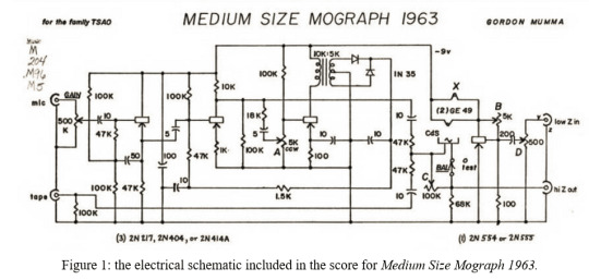
A history of circuit music / schematic as score in quotes and circuit diagrams:
"TRADITIONAL notation has been abandoned in so much of the last decade's music that players are no longer shocked by the prospect of tackling a new set of rules and symbols every time they approach a new composition." (Behrman 1965, 58)
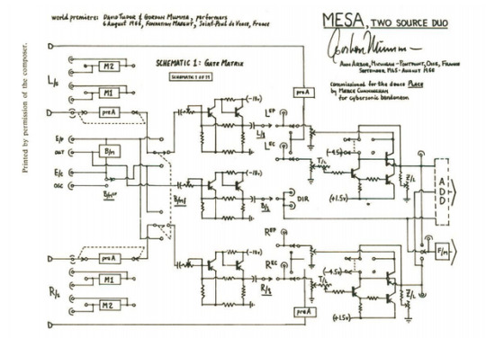
Figure 2: schematic for Mesa by Gordon Mumma, dated 1965-1966, Ann Arbor (Cage 1969, 199). For more, see Goldman (2020). Note this is only one of eleven schematics required to build the circuit-composition.
“My electronic music equipment is designed to be part of my process of composing music. I am like any composer who builds his own instruments, though most of my “instruments'' are inseparable from the compositions themselves. My “end-product” is more than a package of electronic hardware: it is a musical performance for a live audience. On occasion my technical concerns may be differently oriented from those of the usual electronic engineer. Nonetheless, we are concerned with common ground: the applications of electronic technology, in my case to music.” (Mumma 1967, edited 2015, p.43)
“My engineering decisions concerning electronic procedures, circuitry, and configurations are strongly influenced by the requirements of music making. Thus my designing and building of circuits is “composing” that employs electronic technology in the achievement of my musical art. Though I may describe my use of certain electronic procedures because they result in certain sounds, these procedures were not always chosen on a cause-and-effect basis. Sometimes I am looking for a certain kind of sound modification, and I work on various circuits until I have achieved that result. Other times in casually experimenting with different configurations of circuits I may chance upon some novel sound effect that becomes the germinating idea for a piece of music.” (44)
“Independent circuits developed by individual artists represent further development in this genre. Mumma broke ground in this area with his Hornpipe (1967), Mesa (1969) and other circuits. The unique aspect of this type of work lay in the circuit's de facto equivalence to a score.” (Gersham-Lancaster, 1998, 40)
“Another strong concept in Gordon's work is process. Perhaps electronics, which are very process-oriented, have influenced his musical thinking, but perhaps again his thinking, being already process-oriented, had an innate affinity to the concepts of electronic processes. Even his earliest works are process oriented. [...] The electronic network [used in Hornpipe] shapes the process by its own limitations and its own particular dimensions. The circuit is the process is the score is the work itself. The performance is an exploration of what that particular process allows.” (Payne 2000 (written 1976-82), 109-110)
personal communication with Payne, 7/30/2021: "I think that I originally finished the article on Gordon in 1976. I seem to remember that Mimi Johnson later asked for revisions and updates from everyone involved, which is why works dating as late as 1982 are included in my article."
“Due to the evanescent nature of the signal present at the random inputs, the melodic patterns generated by the Pygmy Gamelan are perpetually changing but bound to the metric and modal constraints designed into each unit. In this sense, the electronic circuit itself functions as the score, as well as the instrument and the performer.” ( DeMarinis 1973, 47)
“That was a piece in which that is the score—that is, the instrument, that is that object that does that thing. I was somewhat of a zealot about that idea, of not wanting to make instruments, not wanting to make general-purpose instruments. I thought of myself as thinking much more in the culture of art, making objects that were pieces, sometimes requiring performances, sometimes not, sometimes standing alone.” (DeMarinis in Ouzounian 2010, 12)
“ANDS combines basic concepts of musical instrument, structure, and form into one set of circuits. The structure of any particular performance is determined by coordinations between the players and the circuit. The form of the piece results from relationships that develop among the players in performance. The primary score is the circuit itself. Awareness of the form is necessary for performance. This awareness can best be attained through some direct experience with the instrument and the structure. Someone who understands the circuit-as-score should design rehearsal instructions that will expose the players to the factors that shape the piece.” (Collins 1979, 40)
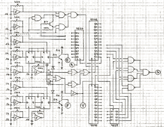
Figure 4: one of the three circuit schematics provided in the score and instructions for ANDS by Nicolas Collins (1979, 40).
“The idea certainly did not originate with me, I was parroting the philosophy a lot of us were following at the time. Composers Inside Electronics started at Chocorua, NH in the summer of 1973. And that in turn built on a notion that Tudor had had for some years, shared with Mumma for sure and likely Behrman (Mumma pre-dates Tudor on several key electronic developments) “ (personal communication with Collins, 12/10/2019)
Collins 2012 p. 26: "In an outtake from his 1976 interview with Robert Ashley for Ashley's Music With Roots in the Aether, Alvin Lucier justified his lack of interest in the hardware of electronic music with the statement, 'Sound is three-dimensional, but circuits are flat.'"
"In Hornpipe and Runthrough, there were no scores to follow; the scores were inherent in the circuitry - that was a new idea for me." (Lucier 1998, 6)
“The circuit—whether built from scratch, a customized commercial device, or store-bought and scrutinized to death—became the score.” (Collins 2004, 1)
"With an open-form score that encouraged experimentation in the design of sound generators and resonated objects, this work served as a creative catalyst for the workshop participants and, later, other young composers who were drawn to Tudor by word-of-mouth." (Collins 2006, 40)
"Immersed in a musical ethos that valued chance, they were highly receptive to accidental discoveries—in the pursuit of the “score within the circuit,” they relished wandering down side paths, rather than race-walking toward a predetermined goal." (Collins 2006, 91).
“Composers traditionally use scores to convey required instructions that the performer must follow to reproduce a series of sound events, or a composition which is executed using a series of commands. Even in the case of semi-improvised graphic scores, like those of Stockhausen, the performer is asked to make various choices within a parameter set. However, when the electronic circuit is transformed into a score, or installed as an auto-generative system, the musical hierarchies of composer, performer, and listener are also transformed, conflating into a facilitator or receptor of signal flow and modulation”. (Eppley and Hart 2016)
bibliography and related texts:
Ashley, Robert. 2000. Music with Roots in the Aether: Interviews with and Essays About Seven American Composers. Köln: MusikTexte.
Behrman, David. 1965. “What Indeterminate Notation Determines.” Perspectives of New Music 3 (2): 58–73.
Beirer, Ingrid, ed. 2011. Paul DeMarinis: Buried In Noise. Heidelberg: Kehrer Verlag.
Blasser, Peter. 2015. “Stores at the Mall.” Master’s Thesis, Wesleyan University.
Braun, Hans-Joachim, ed. 2000. Music and Technology in the Twentieth Century. Baltimore: John Hopkins University Press.
Cage, John. 1969. Notations. New York: Something Else Press.
Collins, Nicolas. 1979. “Three Pieces.” Master’s Thesis, Middletown, Connecticut: Wesleyan University. https://www.nicolascollins.com/texts/Collins_MA_thesis.pdf.
———. 2006. Handmade Electronic Music: The Art of Hardware Hacking. New York: Routledge.
———. 2007. “Live Electronic Music.” In The Cambridge Companion To Electronic Music, 38–54. Cambridge: Cambridge University Press.
———. 2012. “Semiconducting: Making Music After the Transistor.” Seminário Música Ciência Tecnologia 1 (4).
DeMarinis, Paul. 1975. “Pygmy Gamelan.” Asterisk: A Journal of New Music 1 (2): 46–48.
Eppley, Charles. 2016. “Circuit Scores: An Interview with Liz Phillips.” Avant. April 8, 2016. https://web.archive.org/web/20161025062750/http://avant.org/artifact/liz-phillips/.
———. 2017. “Soundsites: Max Neuhaus, Site-Specificity, and the Materiality of Sound as Place.” PhD Thesis, The Graduate School, Stony Brook University: Stony Brook, NY.
Eppley, Charles, and Sam Hart. 2016. “Circuit Scores: Electronics After David Tudor.” Avant (blog). 2016. http://avant.org/event/circuit-scores/.
Getreau, Florence, ed. 2018. Instruments Électriques, Électroniques Et Virtuels. Musique Images Instruments, n. 17. Paris: CNRS Éditions.
Getty Research Institute. 2001. “The Art of David Tudor-Symposium.” Past Events. May 17, 2001. https://www.getty.edu/research/exhibitions_events/events/david_tudor_symposium/.
Goldman, Jonathan, Francis Lecavalier, and Ofer Pelz. 2020. “La Migration Numérique D’une Oeuvre Pionnière Avec Live Electronics. Mesa (1966) De Gordon Mumma.” Revue musicale OICRM 6 (2): 1–24. https://doi.org/10.7202/1068383ar.
Gresham-Lancaster, Scot. 1998. “The Aesthetics and History of the Hub: The Effects of Changing Technology on Network Computer Music.” Leonardo Music Journal 8 (1): 39–44.
Hartman, Lindsey Elizabeth. 2019. “DIY in Early Live Electroacoustic Music: John Cage, Gordon Mumma, David Tudor, and the Migration of Live Electronics from the Studio to Performance.” Baton Rouge: Louisiana State University.
Holzer, Derek. 2010a. “Schematic as Score: Uses and Abuses of the (in) Deterministic Possibilities of Sound Technology.” In Vague Terrain 19, edited by Derek Holzer. https://web.archive.org/web/20131124040627/http://vagueterrain.net/journal19.
———, ed. 2010b. Vague Terrain 19: Schematic as Score. https://web.archive.org/web/20131124040627/http://vagueterrain.net/journal19.
Lucier, Alvin. 1998. “Origins of a Form: Acoustical Exploration, Science and Incessancy.” Leonardo Music Journal 8: 5–11.
Mumma, Gordon. Medium Size Mograph 1963: For Cybersonically Modified Piano with Two Pianists. 1969. Don Mills, Ont.: BMI Canada.
———. 1967a. “Creative Aspects of Live-Performance Electronic Music Technology.” In Audio Engineering Society Convention 33. Audio Engineering Society.
———. 1967b. Medium Size Mograph 1962. Don Mills, Ont.: BMI Canada.
———. 1974. “Witchcraft, Cybersonics, Folkloric Virtuosity.” In Darmstädter Beitrage Zur Neue Musik, Ferienkurse ’74, 14:71–77. Mainz: Musikverlag Schott.
Mumma, Gordon, and Michelle Fillion. 2015. Cybersonic Arts: Adventures in American New Music. Music in American Life. Urbana: University of Illinois Press.
Nakai, You. 2021. Reminded by the Instruments: David Tudor’s Music. Oxford: Oxford University Press.
Nakai, You, and Michael Johnsen. 2020. “The Mumma-Tudor Ring Modulator.” In .
Payne, Maggi. 2000. “The System Is the Composition Itself.” In Music with Roots in the Aether: Interviews with and Essays About Seven American Composers, 109–26. Koln: MusikTexte.
Pinch, Trevor, and Frank Trocco. 2004. Analog Days: The Invention and Impact of the Moog Synthesizer. Cambridge: Harvard University Press.
Turner, Fred. 2010. “The Pygmy Gamelan as Technology of Consciousness.” In Paul DeMarinis: Buried in Noise, 22–31. Heidelberg: Kehrer Verlag.
Weium, Frode, and Tim Boon. 2013. Material Culture and Electronic Sound. Smithsonian Institution Scholarly Press.
0 notes
Text
The electronic structure of atoms

The electronic structure of atoms is the distribution of electrons in molecular or atomic orbitals. These atoms are divided into two types: s-subshell and d-block. These types of atoms exhibit various properties, such as their electrical conductivity and their repulsions. In this article, we will talk about:- - s-subshell - d-block elements - oxygen - hydrogen
s-subshell

The s-subshell electronic structure of atoms describes its electron configuration. The electrons in an s-subshell are located in the d orbitals of atoms. These electrons have the capacity to hold two protons and two neutrons. Normally, electrons are filled in order of energy, with the lowest n-values being filled first. This is called the Madelung rule. The energy of an atomic orbital increases as the principal quantum number (n), increases. Electrons in the 1s orbital have the lowest energy, followed by the 2s, 2p, and 3s orbitals. The energy of the electrons increases with increasing n value. While n has the opposite effect for small atoms. However, the energy of electrons in different subshells can be predicted using certain principles. The s-subshell electronic structure of a chemical atom is dependent on the principal quantum number, n. Subshells have two or three subshells. The s-subshell contains two, six, or even fourteen electrons. The p-subshell, on the other hand, has three subshells. The d-subshell contains five subshells. The f-subshell can hold up to fourteen electrons. The s-subshell electronic structure of a chemical atom is very important for understanding reactivity of an atom. In particular, the p-block atoms like aluminum, beryllium, and magnesium have filled s-subshells. Therefore, beryllium and lithium have similar s-subshell configurations. This means that the s-subshell, the p-block atoms have an electron configuration with a higher energy level than that of the n-block. In addition to the s-subshell electronic structure, an element's atomic configuration reveals the electron distribution across its atomic orbitals. These configurations are shown in a symbolic notation in superscript. And there are useful in identifying elements and compounds. The first atomic number, carbon, has an electronic configuration of 1s22s22p2. The second atom, oxygen, has an atomic number of six and has an s-subshell electronic structure of 2s2p4.
d-block elements

D-block elements in the electronic structure of atoms are defined as elements, whose electrons occupy the d-orbital in the next to last energy level. This orbital is the outermost orbital and is filled with electrons in one of the two forms: either a paired or unpaired. These elements are metals or transition metals. Generally speaking, transition metals are metals that have partially filled d-orbitals, but are not fully filled. D-block elements are characterized by their valence shells, which are in a specific order. This is known as the Aufbau-Hund rule. The electrons in a d-block element usually go into the d-orbital before those in the outermost shell, the 3d orbital. However, this is not true for all elements in the d-block. The s-block is situated between the p and d-block elements and is differentiated by its characteristic properties. A typical s-block element has a higher electronegativity than a p-block one, while a d-block element has a lower one. The p-block elements, on the other hand, are similar in properties to their s-block counterparts. The D-block elements have the largest ionization energy in the electronic structure of atoms. This is directly related to the nuclear charge and inversely proportional to the atomic radii. The first ionization energy for a d-block element increases as its atomic size decreases. The second ionization energy is higher than for an s-block element. The f-block elements are unified by the electrons that reside in their inner f-orbital. There are seven pairs of electrons within the f-block. The f-block elements occupy fourteen columns in the periodic table. These elements are not assigned a group number, but they are grouped together in a row. These elements do not share a common valence shell and do not exhibit a vertical periodic trend.
Hydrogen

Hydrogen is the lightest element in the universe. It is a diatomic molecule with the chemical formula H2. It is colorless, odorless, and tasteless. Hydrogen is non-toxic and highly combustible. Hydrogen's electronic structure is largely unknown. But, it is important in many fields, including medicine, electronics, and the energy industry. Hydrogen occupies the first s orbital, the lowest energy level. It is spherically symmetric around the nucleus, and has one electron per shell. The second type of orbital is called the 2s orbital. It has the same energy as the s orbital, and has two electrons. In the electronic structure of hydrogen, the s orbital is the lowest energy level, while the 2p orbital has the highest energy. The energy levels of hydrogen atoms depend on their orbitals. When an electron moves from its first shell to its second, it has energy E2 and is in the ground state. As the electron travels from one shell to the next, it can move to a higher level, n=2, and finally, n=4 or n=5. In the simplest case, hydrogen bonds with other atoms. This is a result of the hydrogen atoms sharing electrons. These bonds are polar, meaning that the energy of the hydrogen bonding is proportional to the difference in electronegativity of the atoms involved. Unlike covalent bonds, hydrogen bonds can be very weak, with a strength of about 0.01, while those formed by a C-H bond have a much higher electronegativity.
Oxygen

We have discussed the electronic structure of atoms of oxygens, but how do we explain it? Usually, we describe it using the Lewis structure, which has six valence electrons and an outermost shell with eight electrons. In fact, oxygen actually has two more electrons in the outermost shell than it has in the nucleus, so it is more like a 'p' atom. The Lewis structure gives us a very clear picture of the structure of oxygen, which is why we see it drawn as an 'p' atom. An atom's electron configuration depends on the number of electrons in its last orbit. In the case of oxygen, the electron configuration indicates that there are six electrons in this orbit. These electrons are what form the covalent bonds between oxygen atoms. This happens because oxygen atoms always seek to fill the electron in the last orbit. As a result, they form covalent bonds with other atoms. The Lewis formula is a useful first step in understanding covalent bonding. The Couper-Kekule formula, on the other hand, shows shared electron pairs by lines, while the valence electrons are represented by dots. The Couper-Kekule formula was derived from the graphic notations proposed by A. Couper and A. Kekule. However, the formulas do not exactly match the original drawings. The electron configuration of oxygen is very complex. The electrons enter the 1s orbital first, then move through the 2s orbital. Then, another two electrons enter the 2s orbital, and so on. This sequence repeats until the last three electrons enter the 2p orbital. The electron configuration of oxygen is described in an orbital diagram, which can be seen below. It is an excellent example of a chemical bond and explains how the atoms of oxygen interact with one another. https://www.youtube.com/embed/in1j2L7Kf_8 Read the full article
1 note
·
View note
Text
Write the full set of 4 quantum numbers that correspond to the BOLDED electron in each of the following box notation electron configurations
Write the full set of 4 quantum numbers that correspond to the BOLDED electron in each of the following box notation electron configurations
Write the full set of 4 quantum numbers that correspond to the BOLDED electron in each of the following box notation electron configurations 5. 2p 3s 3p 1s 2s 3d 3p 2p 35 15 25

View On WordPress
0 notes
Text
C Valence Electrons

Carbon Valence Electrons Bonding
Carbon Valence Electrons
Valence Electrons & Valency of Hydrogen (H). Valence Electrons & Valency of Carbon (C). Valence Electrons & Valency of Chlorine (Cl). Valency of Oxygen (O) There are many different ways to find out the valency of an atom which reflects the ability of an atom to bond with other atoms. Valence describes how easily an atom or a free radical can. 2 valence electrons. Here's cadmium on the periodic table: Its electron configuration would be Kr 5s^2 4d^10. So, as with most transition metals, it will have 2 valence electrons because the full s orbital, which has the highest principal quantum number, has 2 electrons. One neutral atom of carbon has four valence electrons. An easy way to tell how many valence electrons an element has is to look at the periodic table and find the element's main group number. Carbon is in group 4, which means it has four valence electrons. Valence electrons are the electrons found in an atom's outer electron shell.

Skills to Develop
To understand the basics of adding electrons to atomic orbitals
To understand the basics of the Aufbau principle
The electron configuration of an element is the arrangement of its electrons in its atomic orbitals. By knowing the electron configuration of an element, we can predict and explain a great deal of its chemistry.
The Aufbau Principle
We construct the periodic table by following the aufbau principle (from German, meaning “building up”). First we determine the number of electrons in the atom; then we add electrons one at a time to the lowest-energy orbital available without violating the Pauli principle. We use the orbital energy diagram of Figure 2.1.1, recognizing that each orbital can hold two electrons, one with spin up ↑, corresponding to ms = +½, which is arbitrarily written first, and one with spin down ↓, corresponding to ms = −½. A filled orbital is indicated by ↑↓, in which the electron spins are said to be paired. Here is a schematic orbital diagram for a hydrogen atom in its ground state:
Some authors express the orbital diagram horizontally (removing the implicit energy axis and the colon symbol):
Unless there is a reason to show the empty higher energy orbitals, these are often omitted in an orbital diagram:
From the orbital diagram, we can write the electron configuration in an abbreviated form in which the occupied orbitals are identified by their principal quantum number n and their value of l (s, p, d, or f), with the number of electrons in the subshell indicated by a superscript. For hydrogen, therefore, the single electron is placed in the 1s orbital, which is the orbital lowest in energy (Figure 2.1.1), and the electron configuration is written as 1s1 and read as “one-s-one.”
A neutral helium atom, with an atomic number of 2 (Z = 2), has two electrons. We place one electron in the orbital that is lowest in energy, the 1s orbital. From the Pauli exclusion principle, we know that an orbital can contain two electrons with opposite spin, so we place the second electron in the same orbital as the first but pointing down, so that the electrons are paired. The orbital diagram for the helium atom is therefore
written as 1s2, where the superscript 2 implies the pairing of spins. Otherwise, our configuration would violate the Pauli principle.
The next element is lithium, with Z = 3 and three electrons in the neutral atom. We know that the 1s orbital can hold two of the electrons with their spins paired. Figure 2.1.1 tells us that the next lowest energy orbital is 2s, so the orbital diagram for lithium is
Cyberlink powerdirector 9 ultra free. download full version. This electron configuration is written as 1s2 2s1.
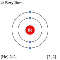
The next element is beryllium, with Z = 4 and four electrons. We fill both the 1s and 2s orbitals to achieve a 1s2 2s2 electron configuration:
When we reach boron, with Z = 5 and five electrons, we must place the fifth electron in one of the 2p orbitals. Because all three 2p orbitals are degenerate, it doesn’t matter which one we select. The electron configuration of boron is 1s2 2s2 2p1:
At carbon, with Z = 6 and six electrons, we are faced with a choice. Should the sixth electron be placed in the same 2p orbital that already has an electron, or should it go in one of the empty 2p orbitals? If it goes in an empty 2p orbital, will the sixth electron have its spin aligned with or be opposite to the spin of the fifth?
Which of the following three orbital diagrams is correct for carbon, remembering that the 2p orbitals are degenerate?
Because of electron-electron repulsions, it is more favorable energetically for an electron to be in an unoccupied orbital than in one that is already occupied; hence we can eliminate choice a. Similarly, experiments have shown that choice b is slightly higher in energy (less stable) than choice c because electrons in degenerate orbitals prefer to line up with their spins parallel; thus, we can eliminate choice b. Choice c illustrates Hund’s rule (named after the German physicist Friedrich H. Hund, 1896–1997), which today says that the lowest-energy electron configuration for an atom is the one that has the maximum number of electrons with parallel spins in degenerate orbitals. By Hund’s rule, the electron configuration of carbon, which is 1s2 2s2 2p2, is understood to correspond to the orbital diagram shown in c. Experimentally, it is found that the ground state of a neutral carbon atom does indeed contain two unpaired electrons.
Exercise 2.2.1
Draw an orbital diagram for nitrogen, Z = 7. What is the electron configuration of this atom?
Answer:
When we get to nitrogen (Z = 7, with seven electrons), Hund’s rule tells us that the lowest-energy arrangement is
with three unpaired electrons. The electron configuration of nitrogen is thus 1s2 2s2 2p3.
At oxygen, with Z = 8 and eight electrons, we have no choice. One electron must be paired with another in one of the 2p orbitals, which gives us two unpaired electrons and a 1s2 2s2 2p4 electron configuration. Because all the 2p orbitals are degenerate, it doesn’t matter which one has the pair of electrons.
Similarly, fluorine has the electron configuration 1s2 2s2 2p5 and the orbital diagram is:
When we reach neon, with Z = 10, we have filled the 2p subshell, giving a 1s2 2s2 2p6 electron configuration and an orbital diagram of:
Notice that for neon, as for helium, all the orbitals through the 2p level are completely filled. This fact is very important in dictating both the chemical reactivity and the bonding of helium and neon, as you will see.
Core and Valence Electrons
As we continue through the periodic table in this way, writing the electron configurations of larger and larger atoms, it becomes tedious to keep copying the configurations of the filled inner subshells. In practice, chemists simplify the notation by using a bracketed noble gas symbol to represent the configuration of the noble gas from the preceding row because all the orbitals in a noble gas are filled. For example, (Ne) represents the 1s2 2s2 2p6 electron configuration of neon (Z = 10), so the electron configuration of sodium, with Z = 11, which is 1s2 2s2 2p6 3s1, is written as (Ne) 3s1
Full Electron ConfigurationNobel Gas ShorthandNeonZ = 10Ne: 1s2 2s2 2p6Ne: (He) 2s2 2p6SodiumZ = 11
Na: 1s2 2s2 2p6 3s1
Na: (Ne) 3s1
Carbon Valence Electrons Bonding
Electrons in filled inner orbitals are closer to the nucleus and more tightly bound to it, and therefore they are rarely involved in chemical reactions. We will call these core electrons. For the representative elements (columns 1, 2, and 13-18 of the Periodic Table), the core electrons are all electrons with an n-value lower than the maximum n-value in the electron configuration. For example, in the sodium atom the highest n-value is 3. Thus, the core electrons are those in the atomic orbitals with n < 3, namely those in the 1s, 2s and 2p orbitals. So, sodium has 10 core electrons. We will revisit this definition of core electrons later on for transition metals.
This means that the chemistry of an atom depends mostly on the electrons in its outermost shell, those with the highest n-value, which are called the valence electrons. The simplified notation allows us to see the valence-electron configuration more easily. Using this notation to compare the electron configurations of sodium and lithium, we have:
Sodium1s2 2s2 2p6 3s1(Ne) 3s1Lithium1s2 2s1(He) 2s1
It is readily apparent that both sodium and lithium have one s electron in their valence shell. We would therefore predict that sodium and lithium have very similar chemistry, which is indeed the case.
As we continue to build the eight elements of period 3, the 3s and 3p orbitals are filled, one electron at a time. This row concludes with the noble gas argon, which has the electron configuration (Ne) 3s2 3p6, corresponding to a filled valence shell.
Example 2.2.2
Draw an orbital diagram and use it to derive the electron configuration of phosphorus, Z = 15. What is its valence electron configuration?
Given: atomic number
Asked for: orbital diagram and valence electron configuration for phosphorus
Strategy:
Locate the nearest noble gas preceding phosphorus in the periodic table. Then subtract its number of electrons from those in phosphorus to obtain the number of valence electrons in phosphorus.
Referring to Figure 2.1.1, draw an orbital diagram to represent those valence orbitals. Following Hund’s rule, place the valence electrons in the available orbitals, beginning with the orbital that is lowest in energy. Write the electron configuration from your orbital diagram.
Ignore the inner orbitals (those that correspond to the electron configuration of the nearest noble gas) and write the valence electron configuration for phosphorus.
Solution:

A Because phosphorus is in the third row of the periodic table, we know that it has a (Ne) closed shell with 10 electrons. We begin by subtracting 10 electrons from the 15 in phosphorus.
B The additional five electrons are placed in the next available orbitals, which Figure 2.1.1 tells us are the 3s and 3p orbitals:
Because the 3s orbital is lower in energy than the 3p orbitals, we fill it first:
Hund’s rule tells us that the remaining three electrons will occupy the degenerate 3p orbitals separately but with their spins aligned:
The electron configuration is (Ne) 3s2 3p3.
C We obtain the valence electron configuration by ignoring the inner orbitals, which for phosphorus means that we ignore the (Ne) closed shell. This gives a valence-electron configuration of 3s2 3p3.
Exercise 2.2.2
Draw an orbital diagram and use it to derive the electron configuration of chlorine, Z = 17. What is its valence electron configuration?
Answer:
(Ne) 3s2 3p5
Valence electron configuration: 3s23p5

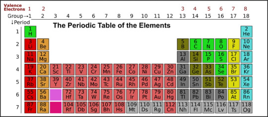
The general order in which orbitals are filled is depicted in Figure 2.2.1. Subshells corresponding to each value of n are written from left to right on successive horizontal lines, where each row represents a row in the periodic table. The order in which the orbitals are filled is indicated by the diagonal lines running from the upper right to the lower left. Accordingly, the 4s orbital is filled prior to the 3d orbital because of shielding and penetration effects. Consequently, the electron configuration of potassium, which begins the fourth period, is (Ar) 4s1, and the configuration of calcium is (Ar) 4s2. Five 3d orbitals are filled by the next 10 elements, the transition metals, followed by three 4p orbitals. Notice that the last member of this row is the noble gas krypton (Z = 36), Kr: (Ar) 4s2 3d10 4p6, which has filled 4s, 3d, and 4p orbitals. The fifth row of the periodic table is essentially the same as the fourth, except that the 5s, 4d, and 5p orbitals are filled sequentially.
Figure 2.2.1Predicting the Order in Which Orbitals Are Filled in Multielectron Atoms. If you write the subshells for each value of the principal quantum number on successive lines, the observed order in which they are filled is indicated by a series of diagonal lines running from the upper right to the lower left.
The sixth row of the periodic table will be different from the preceding two because the 4f orbitals, which can hold 14 electrons, are filled between the 6s and the 5d orbitals. The elements that contain 4f orbitals in their valence shell are the lanthanides. When the 6p orbitals are finally filled, we have reached the next (and last known) noble gas, radon (Z = 86), Rn: (Xe) 6s2 4f14 5d10 6p6. In the last row, the 5f orbitals are filled between the 7s and the 6d orbitals, which gives the 14 actinide elements. Because the large number of protons makes their nuclei unstable, all the actinides are radioactive.
Example 2.2.3
Write the electron configuration of mercury (Z = 80), showing all the inner orbitals.
Given: atomic number
Asked for: complete electron configuration R markdown code.
Strategy:

Using the orbital diagram in Figure 2.2.1 and the periodic table as a guide, fill the orbitals until all 80 electrons have been placed.
Solution:
By placing the electrons in orbitals following the order shown in Figure 2.2.1 and using the periodic table as a guide, we obtain
1s2row 12 electrons2s22p6row 28 electrons3s23p6row 38 electrons4s23d104p6row 418 electrons5s24d105p6row 518 electronsrow 1–554 electrons
After filling the first five rows, we still have 80 − 54 = 26 more electrons to accommodate. According to Figure 2.2.2, we need to fill the 6s (2 electrons), 4f (14 electrons), and 5d (10 electrons) orbitals. The result is mercury’s electron configuration:
Hg: 1s2 2s2 2p6 3s2 3p6 4s2 3d10 4p6 5s2 4d10 5p6 6s2 4f14 5d10
Hg: (Xe) 6s2 4f14 5d10
with a filled 5d subshell, a 6s2 4f14 5d10 valence shell configuration, and a total of 80 electrons. (You should always check to be sure that the total number of electrons equals the atomic number.)
Exercise 2.2.3
Although element 114 is not stable enough to occur in nature, two isotopes of element 114 were created for the first time in a nuclear reactor in 1999 by a team of Russian and American scientists. Write the complete electron configuration for element 114.
Answer:
1s2 2s2 2p6 3s2 3p6 4s2 3d10 4p6 5s2 4d10 5p6 6s2 4f14 5d10 6p6 7s2 5f14 6d10 7p2
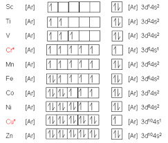
The electron configurations of the elements are presented in Figure 2.2.3, which lists the orbitals in the order in which they are filled. In several cases, the ground state electron configurations are different from those predicted by Figure 2.2.1. Some of these anomalies occur as the 3d orbitals are filled. For example, the observed ground state electron configuration of chromium is (Ar) 4s1 3d5 rather than the predicted (Ar) 4s2 3d4. Similarly, the observed electron configuration of copper is (Ar) 4s1 3d10 instead of (Ar) s2 3d9. The actual electron configuration may be rationalized in terms of an added stability associated with a half-filled (ns1, np3, nd5, nf7) or filled (ns2, np6, nd10, nf14) subshell. Given the small differences between higher energy levels, this added stability is enough to shift an electron from one orbital to another. In heavier elements, other more complex effects can also be important, leading to some of the additional anomalies indicated in Figure 2.2.3. For example, cerium has an electron configuration of (Xe) 6s2 4f1 5d1, which is impossible to rationalize in simple terms. In most cases, however, these apparent anomalies do not have important chemical consequences.
Note
The Apache HTTP Server Project is pleased to announce the release of version 2.4.46 of the Apache HTTP Server ('Apache' and 'httpd'). This version of Apache is our latest GA release of the new generation 2.4.x branch of Apache HTTPD and represents fifteen years of innovation by the project, and is recommended over all previous releases! Additional notes. Note that the versions of Apache HTTP Server included in the above products are in most cases vastly different from the upstream community releases of the same version. This is explained by Red Hat's Security Backporting Policy and is the most common cause of admins/auditors trying to get a newer version of Apache; For example: EWS 2.1.0 & EAP 6.4.0 include Apache httpd. https://huntergate391.tumblr.com/post/658770617547571200/httpd-version. The Apache HTTP Server ('httpd') was launched in 1995 and it has been the most popular web server on the Internet since April 1996. It has celebrated its 25th birthday as a project in February 2020. The Apache HTTP Server is a project of The Apache Software Foundation. Apache httpd 2.4.46 Released 2020-08-07 ¶.
Additional stability is associated with half-filled or filled subshells.
Summary
Carbon Valence Electrons
Based on the Pauli principle and a knowledge of orbital energies obtained using hydrogen-like orbitals, it is possible to construct the periodic table by filling up the available orbitals beginning with the lowest-energy orbitals (the aufbau principle), which gives rise to a particular arrangement of electrons for each element (its electron configuration). Hund’s rule says that the lowest-energy arrangement of electrons is the one that places them in degenerate orbitals with their spins parallel. For chemical purposes, the most important electrons are those in the outermost principal shell, the valence electrons.
0 notes
Text
Braille Facts: Unveiling the Tactile Writing System
Braille, the revolutionary tactile writing system, has been transforming lives since its inception in the early 19th century. Named after its creator, Louis Braille, this system of raised dots allows visually impaired individuals to read and write independently, breaking barriers to education, employment, and personal development.
The Origins of Braille
Louis Braille, a Frenchman who lost his sight due to a childhood accident, developed the Braille system when he was just 15 years old. Inspired by a military communication code known as "night writing," Braille simplified and refined the system, creating a matrix of six dots. This matrix forms the foundation of the Braille alphabet, with each letter, number, and punctuation mark represented by different combinations of raised dots.
How Braille Works
The basic unit of Braille is the "cell," which consists of six dots arranged in a rectangular formation, three dots high and two dots wide. The dots are numbered 1 through 6, starting from the top left. Various combinations of these dots represent different characters:
A: Dot 1
B: Dots 1 and 2
C: Dots 1 and 4
D: Dots 1, 4, and 5
E: Dots 1 and 5
Numbers and punctuation marks have their specific dot configurations, and capital letters are indicated by a special prefix.
The Importance of Braille
Braille literacy is crucial for the visually impaired. It enables individuals to access a wealth of information, from literature and educational materials to music and technology. Reading Braille enhances spelling, grammar, and comprehension skills, providing a solid foundation for academic and professional success.
Modern Uses of Braille
With technological advancements, Braille has evolved beyond traditional paper. Today, Braille displays and keyboards enable seamless interaction with digital devices. These electronic tools translate on-screen text into Braille in real-time, allowing users to navigate the internet, read emails, and write documents with ease.
Moreover, public spaces are increasingly incorporating Braille. From elevator buttons to restroom signs, the presence of Braille ensures accessibility and inclusivity for all.
Fun Facts About Braille
Global Reach: Braille is not limited to any single language. It has been adapted for numerous languages worldwide, including Chinese, Arabic, and Russian.
Musical Notation: Louis Braille also created a system for writing music in Braille, enabling visually impaired musicians to read and compose music.
Literary Richness: The first book published in Braille was “The Gospel of Mark” in 1837. Today, countless books are available in Braille, covering all genres and interests.
Public Recognition: World Braille Day, celebrated on January 4th, honors Louis Braille’s birthday and raises awareness about the importance of Braille literacy.
Challenges and Advocacy
Despite its benefits, Braille literacy rates are declining, partly due to the increasing reliance on audio books and voice-recognition software. Advocacy groups emphasize the importance of maintaining Braille education to ensure that visually impaired individuals have the skills needed for independence and employment.
Conclusion
Braille remains a cornerstone of communication for the visually impaired, symbolizing empowerment and accessibility. Its enduring relevance and adaptability to modern technology ensure that it will continue to be a vital tool for millions around the world. By understanding and supporting Braille literacy, we contribute to a more inclusive and equitable society.
1 note
·
View note
Text
What is Electron Configuration?
Electron Configuration is defined as the distribution of electrons in different atomic orbitals of an element. Moreover, in order to represent the electron configuration of an element, an electron-containing subshell, along with the number of electrons in it, is shown as a sequence. For instance, in hydrogen, the electronic configuration is represented as 1s1.
But not all element electron configurations can be represented in standard forms because of their length due to large atomic numbers. In such cases, an abbreviated notation is employed to describe electron configuration. And in this abbreviated notation, the atomic subshells of the noble gas electronic configuration are replaced by the noble gas symbols inside a square bracket.
Uses of Electronic Configuration
Now that we have a good understanding of the Electronic Configuration. Let us now talk about the various benefits or the importance of Electronic Configuration.
· To understand the atomic spectra of various elements, an Electron Configuration is essential
· As explained above, the properties of the elements can only find out using electronic configuration
· Besides this, the valency of all elements directly depends on the number of electrons in an atomic orbital, which in turn is determined using electronic configuration
How to represent Electronic Configuration?
Moving on to our next topic, how to write the Electronic Configuration for various elements. Regardless of the method, this process mainly depends on three main steps Shells, Subshells, and Notations.
Shells
Firstly, in shells, the maximum no of electrons is accommodated based on the type of element and more importantly, on the principal quantum number (n). Thus, based on the shell, the principal quantum number varies. For instance, in the first shell, which is K, the principal quantum number n is 1. Below are some examples of shells and their principal quantum numbers.
Subshells
Unlike the shells, the subshells are categorized with the help of the azimuthal quantum number (I). However, this quantum number is directly dependent on the principal quantum number (n). And therefore, based on the number of shells in an element, the subshells also vary.
Notation
The notations are basically the subshell labels, which include the subshells name, shell number as well as the electrons in the subshell (represented using superscript).
If you find any other similar topics from the chemistry subject harder to understand, then you can check out the online interactive classes offered by Tutoroot. At Tutoroot, we are geared towards helping you get the best ranks and scores in academics by providing classes that are interactive and easy to follow.
0 notes
Text
The electronic structure of atoms

The electronic structure of atoms is the distribution of electrons in molecular or atomic orbitals. These atoms are divided into two types: s-subshell and d-block. These types of atoms exhibit various properties, such as their electrical conductivity and their repulsions. In this article, we will talk about:- - s-subshell - d-block elements - oxygen - hydrogen
s-subshell
The s-subshell electronic structure of atoms describes its electron configuration. The electrons in an s-subshell are located in the d orbitals of atoms. These electrons have the capacity to hold two protons and two neutrons. Normally, electrons are filled in order of energy, with the lowest n-values being filled first. This is called the Madelung rule. The energy of an atomic orbital increases as the principal quantum number (n), increases. Electrons in the 1s orbital have the lowest energy, followed by the 2s, 2p, and 3s orbitals. The energy of the electrons increases with increasing n value. While n has the opposite effect for small atoms. However, the energy of electrons in different subshells can be predicted using certain principles. The s-subshell electronic structure of a chemical atom is dependent on the principal quantum number, n. Subshells have two or three subshells. The s-subshell contains two, six, or even fourteen electrons. The p-subshell, on the other hand, has three subshells. The d-subshell contains five subshells. The f-subshell can hold up to fourteen electrons. The s-subshell electronic structure of a chemical atom is very important for understanding reactivity of an atom. In particular, the p-block atoms like aluminum, beryllium, and magnesium have filled s-subshells. Therefore, beryllium and lithium have similar s-subshell configurations. This means that the s-subshell, the p-block atoms have an electron configuration with a higher energy level than that of the n-block. In addition to the s-subshell electronic structure, an element's atomic configuration reveals the electron distribution across its atomic orbitals. These configurations are shown in a symbolic notation in superscript. And there are useful in identifying elements and compounds. The first atomic number, carbon, has an electronic configuration of 1s22s22p2. The second atom, oxygen, has an atomic number of six and has an s-subshell electronic structure of 2s2p4.
d-block elements
D-block elements in the electronic structure of atoms are defined as elements, whose electrons occupy the d-orbital in the next to last energy level. This orbital is the outermost orbital and is filled with electrons in one of the two forms: either a paired or unpaired. These elements are metals or transition metals. Generally speaking, transition metals are metals that have partially filled d-orbitals, but are not fully filled. D-block elements are characterized by their valence shells, which are in a specific order. This is known as the Aufbau-Hund rule. The electrons in a d-block element usually go into the d-orbital before those in the outermost shell, the 3d orbital. However, this is not true for all elements in the d-block. The s-block is situated between the p and d-block elements and is differentiated by its characteristic properties. A typical s-block element has a higher electronegativity than a p-block one, while a d-block element has a lower one. The p-block elements, on the other hand, are similar in properties to their s-block counterparts. The D-block elements have the largest ionization energy in the electronic structure of atoms. This is directly related to the nuclear charge and inversely proportional to the atomic radii. The first ionization energy for a d-block element increases as its atomic size decreases. The second ionization energy is higher than for an s-block element. The f-block elements are unified by the electrons that reside in their inner f-orbital. There are seven pairs of electrons within the f-block. The f-block elements occupy fourteen columns in the periodic table. These elements are not assigned a group number, but they are grouped together in a row. These elements do not share a common valence shell and do not exhibit a vertical periodic trend.
Hydrogen

Hydrogen is the lightest element in the universe. It is a diatomic molecule with the chemical formula H2. It is colorless, odorless, and tasteless. Hydrogen is non-toxic and highly combustible. Hydrogen's electronic structure is largely unknown. But, it is important in many fields, including medicine, electronics, and the energy industry. Hydrogen occupies the first s orbital, the lowest energy level. It is spherically symmetric around the nucleus, and has one electron per shell. The second type of orbital is called the 2s orbital. It has the same energy as the s orbital, and has two electrons. In the electronic structure of hydrogen, the s orbital is the lowest energy level, while the 2p orbital has the highest energy. The energy levels of hydrogen atoms depend on their orbitals. When an electron moves from its first shell to its second, it has energy E2 and is in the ground state. As the electron travels from one shell to the next, it can move to a higher level, n=2, and finally, n=4 or n=5. In the simplest case, hydrogen bonds with other atoms. This is a result of the hydrogen atoms sharing electrons. These bonds are polar, meaning that the energy of the hydrogen bonding is proportional to the difference in electronegativity of the atoms involved. Unlike covalent bonds, hydrogen bonds can be very weak, with a strength of about 0.01, while those formed by a C-H bond have a much higher electronegativity.
Oxygen

We have discussed the electronic structure of atoms of oxygens, but how do we explain it? Usually, we describe it using the Lewis structure, which has six valence electrons and an outermost shell with eight electrons. In fact, oxygen actually has two more electrons in the outermost shell than it has in the nucleus, so it is more like a 'p' atom. The Lewis structure gives us a very clear picture of the structure of oxygen, which is why we see it drawn as an 'p' atom. An atom's electron configuration depends on the number of electrons in its last orbit. In the case of oxygen, the electron configuration indicates that there are six electrons in this orbit. These electrons are what form the covalent bonds between oxygen atoms. This happens because oxygen atoms always seek to fill the electron in the last orbit. As a result, they form covalent bonds with other atoms. The Lewis formula is a useful first step in understanding covalent bonding. The Couper-Kekule formula, on the other hand, shows shared electron pairs by lines, while the valence electrons are represented by dots. The Couper-Kekule formula was derived from the graphic notations proposed by A. Couper and A. Kekule. However, the formulas do not exactly match the original drawings. The electron configuration of oxygen is very complex. The electrons enter the 1s orbital first, then move through the 2s orbital. Then, another two electrons enter the 2s orbital, and so on. This sequence repeats until the last three electrons enter the 2p orbital. The electron configuration of oxygen is described in an orbital diagram, which can be seen below. It is an excellent example of a chemical bond and explains how the atoms of oxygen interact with one another. https://www.youtube.com/embed/in1j2L7Kf_8 Read the full article
0 notes
Text
Battery Charging
"If I charge my phone when it is at 50% capacity to full 100% capacity, would it be the same "1" charge as if I charged it from 20% to 100% capacity?"
To answer this question completely and to avoid confusion I will start with the basics and do my best to answer people who have doubts!
To begin with battery capacity is a reference to the total amount of energy stored within a battery. It is a mathematical calculation to determine how long a battery will run (power a device) before the battery "dies". Battery capacity is rated in Ampere-hours (Ah), which is the product of: Ah= Current X Hours to Total Discharge.
As with all metric measurements, Amps can be divided into smaller (or larger) units by adding a prefix. For example a milliAmp hour (mAh) is most commonly used capacity notation on small batteries. A small battery that is rated 1000 mAh can be rewritten to read as 1 Ah.
Secondly, Amp hours do not dictate the flow of electrons at any given moment but instead measures remaining electron flow per charge. Amperes (Amps ) is a measurement of quantity of the number of electrons passing through a given wire per second. For every second your battery is on Per second there are 62,000,000,000,000,000,000 electrons passing through your battery. This electron flow, once started will never stop even if you disconnect your battery from your device and is the primary reason why batteries in time "die".
You see when you charge a battery what you are technically doing is introducing electrons into the batteries chemical housed inside the battery cell. This electron introduction is called intercalation. Intercalation is the joining of a molecule (or molecule group) between two other molecules (or groups). When it comes to charging your battery you are in effect pushing ions in and out of solid lithium compounds (or other chemical types). These compounds have minuscule spaces between their crystallized planes for small ions, such as lithium, to insert themselves from a force of current (i.e. wall or car charger). In effect ionizing the lithium loads the crystal planes to the point where they are forced into a current flow. The current flow is then channeled back and forth from anode to cathode and thereby creating an electrical flow to power on your device. This flow can never stop once started.
Intercalation is the process that creates the electrochemical reaction inside the battery and allows the battery to replenish electrons as the battery is used. It is in essence the catalyst to move chemical compounds. This normal and how batteries were designed. To move a chemical (lithium-ion, lithium polymer, lithium iron phosphate, etc) you have to have a minimum voltage applied. Most small battery cells are charged to 4.2 volts with relative safe workings at about 3.8 volts. Anything less than 3.3 volts will not be enough to charge or move the chemistry.
Now when we ask how long will my battery "last" we have to know that battery life varies depending on device configuration, model, applications loaded on the product, power management settings of the product, and the product features used. In addition to usage patterns battery life decreases every time you replenish electrons (i.e. charge your battery). This is called battery degradation and power loss and this is simply the normal use of any battery. Battery degradation and power loss varies with each battery and when it occurs it simply means that your battery has reached a point where it can no longer accept a charge and recharge the chemical inside your battery.
There are five overarching factors that govern battery capacity and they include:
Physical Size – the amount of capacity that can be stored in the casing of any battery depends on the volume and plate area of the actual battery. The more volume and plate area the more capacity you can actually store in a battery.
Temperature – capacity, energy store decreases as a battery gets colder. High temperatures also have an effect on all other aspects of your battery.
Cut off Voltage – To prevent damage to the battery and the device batteries have an internal mechanism that stops voltage called the cut-off voltage, which is tpically limited to 1.67V or 10V for a 12 Volt battery. Letting a battery self-discharge to zero destroys the battery.
Discharge rate – The rate of discharge, the rate at which a battery goes from a full charge to the cut off voltage measured in amperes. As the rate goes up, the capacity goes down.
Battery History – Deep discharging, excessive cycling, age, over charging, under charging, all reduce capacity. Note charging your battery 1 time will reduce capacity as much as 15%-20% depending on your battery's chemistry.
Now with all of the above laid we can look at your original question with greater understanding. Your question was:
"If I charge my phone when it is at 50% capacity to full 100% capacity, would it be the same "1" charge as if I charged it from 20% to 100% capacity?"
We know that the life of a lithium based rechargeable battery operating under normal conditions is generally up to 500 charge-discharge cycles with the maximum capacity decreasing with each charge-discharge cycle. NICD or NIMH batteries can last up to 800 charge-discharge cycles
Charge-discharge cycling a battery means to completely discharge (or drain) a battery's created electricity to where there is a charge of less than a 1% capacity remaining. At this point the power to the device will cease and your device will power off. Then after the power is off you recharge the battery to 100% capacity using a power adapter from a wall socket for example. Regardless of how you charge the battery that process of discharging and charging represents one complete charge cycle.
A battery in generally can have between 300-500 charge-discharge cycles (for lithium based chemistries – NIMH can have up to 800 charge-discharge cycles and NICD chemistries can have more). A charge-discharge cycle means that a battery once at 100% draws power down to 0%. Then after recharge it will be back at 100%. This can be done 300-500 times on the same battery. Also with each charge-discharge cycle the runtime (time between charges) is reduced by the gradual depletion and usage of the battery's chemistry inside. For example you may notice in the first 3-4 months you are getting between 3-5 hours of runtime on your battery. Then in month 5-12 (after your purchase) you notice that you are slowly getting less and less runtime in between charges. This is the normal use of the chemistry inside your battery and DOES NOT mean that the battery is bad or defective, but simply has been used by you.
Now one complete charge-discharge cycle means that you draw your batteries capacity (the abiltity to run your battery) from 100% down to 0%. If you draw the battery from 100% to 50% capacity then recharge the battery back to 100% that would represent ½ a charge-discharge cycle. Now technically this is different than running your battery from 100% to 20% then recharging.
Now if you plug your device in 4 times a day to recharge it whether it starts at 20% or 90% then each recharge would be some percentage of one complete charge-discharge cycle. Again each complete charge-discharge cycle does degrade the lifespan of the battery by a small percentage.
Now one thing that should also help is that inside your battery are integrated power management circuits that protect your battery and device against over-voltage and under-voltage conditions. The power management circuits also maximize battery life between charges, minimize charging times, and improve overall battery life. So no need to worry about leaving your battery on your charger – when the battery is done charging it will simply stop accepting a charge!
Now keeping all the above in mind does it make sense to keep your device plugged in continuously if each charge-discharge cycle does degrade the lifespan of the battery by a small percentage? Each person has to make their own conclusion to that question. If your battery is near the end of its useful life then of course you will find that you must constantly recharge your battery but if your battery is new then it does not need to stay on the charger as frequently. I typically wait till my battery is almost dead before I recharge unless I know I will be away from any means of charging the battery.
Hope it helps everyone!
0 notes
Photo

Is Deno the next big thing?
#472 — January 24, 2020
Read on the Web
JavaScript Weekly
▶ A Look at Deno: Could It Supplant Node (One Day)? — Over the past couple of years, we’ve mentioned Deno a few times. It’s a 'new' JavaScript and TypeScript runtime initially created by Ryan Dahl, the creator of Node, so it’s interesting to see how he thinks things should be done nowadays. Version 1.0 is due soon and we'll feature it in more detail then.
Bert Belder
A Guide to ESLint Configuration and Best Practices — A start-to-finish walkthrough aimed at beginners or anyone who usually just copy/pastes settings until things work. This will help you really understand what’s going on.
Lucas Santoni
React Hooks Guide: See the In-Depth Tutorials with Examples — This guide serves as an exhaustive resource for learning the built-in Hooks that are now part of React. Learn all about them as we comprehensively cover: State and Effects, Context, Reducers, and Custom React Hooks. Start learning today.
Progress KendoReact sponsor
TypeOfNaN JavaScript Quiz Questions — A set of 72 (so far) multiple choice questions to test out your JavaScript knowledge. Give it a try over the weekend :-)
Nick Scialli
Playwright: A Node Library to Automate Chromium, Firefox and WebKit — If you’re familiar with Puppeteer for automating Chrome/Chromium, this is in a similar vein for multiple browsers and is being worked on by some of the same contributors. The goal? To be vendor-neutral and to make the APIs more testing-friendly than Puppeteer.
Microsoft
⚡️ Quick Releases
Node 13.7.0
Jest 25.1 — Popular testing solution.
CodeMirror 5.51 — Powerful code editor control.
Vue 3.0.0 alpha 3
💻 Jobs
Full Stack Engineer — Expensify seeks a self-driven individual passionate about making code effective, with an understanding of algorithms and design patterns.
Expensify
Programmer — Basecamp (Remote) — Join our Research & Fidelity team and help shape the front end of our Rails apps and expand our suite of open-source JavaScript frameworks.
Basecamp
Find a Job Through Vettery — Vettery is completely free for job seekers. Make a profile, name your salary, and connect with hiring managers from top employers.
Vettery
📘 Articles & Tutorials
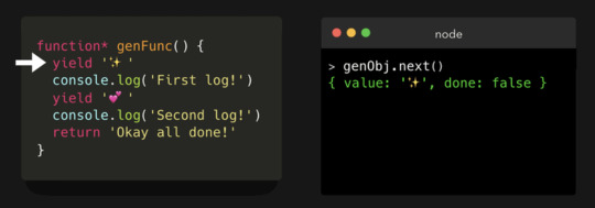
JavaScript Visualized: Generators and Iterators — An easily accessible introduction to generator functions with code and animated examples.
Lydia Hallie
How to Pass Data Between Components in Vue.js — With several ways to share data across components, it’s worth spending some time to reflect on what best suits your situation.
Matt Maribojoc
Writing Dependency-Free JavaScript — If you really need to have no dependencies at all, these tips may help.
Magnus Hovland Hoff
▶ Scaling Telecommunications Data with a Service Mesh — Luca Maraschi, a TELUS Digital chief architect, shares how they serve massive volumes of data to millions of customers.
Heroku sponsorpodcast
JavaScript Tree Shaking, Like A Pro — Eliminating dead code is becoming an essential practice, to avoid large bundle sizes and improve performance. But “as a general rule of thumb: predicting how Webpack will behave for a given module, is not easy to do by eye.”
Daniel Brain
The Best Way to Build Reactive Sub-Forms with Angular — Learn how to extract repetitive sub-form implementations into standalone, robust and type safe components.
Tomas Trajan
How We Do Efficient TDD with Karma and Webpack — How Bamboo has made the act of writing a unit test, running the test and seeing feedback into a fast, iterative process for their developers.
Josh Hale
TypeScript's Secret Parallel Universe — How TypeScript handles name clashes between types and variables.
Florian Reuschel
A Basic Introduction to 'Big O' Notation via JS — This article won’t get you through a CS degree(!) but if you’ve heard people talking about things like “O(n) complexity”, it’ll help.
Joshua Hall
The 10 Most Important JavaScript Frameworks of The Past Decade? — It’s a bit of a listicle by definition, but covers frontend, backend, and native and broadly matches up with our experiences. Where’s Ember though?
Ovie Okeh
How We Replaced Mocha with Jest
Ákos K
🔧 Code & Tools

React Nice Dates: Responsive, Touch-Friendly Modular Date Picker — Another month, another date picker, but this seems to be a pretty good one. Lots of demos and code examples and the control itself feels good.
Hernán Sartorio
Time-Travel Debugger for JavaScript and TypeScript — Move forward and backwards through your code to understand the conditions that led to a specific bug, view runtime values, edit-and-continue, and more.
Wallaby.js sponsor
Panzoom: A Universal Panning and Zooming Library — Here’s a live demo.
Andrei Kashcha
Ava 3.0 Released: The Popular Test Runner — A popular test runner for Node with a concise API, detailed error output, etc. 3.0 drops built-in Babel support due to advancements in Node’s native modern JavaScript support and this has some implications for how you’ll write your tests so take care with this upgrade and read this post first.
AVA
Proton Native V2: React, but for Desktop Apps — Make cross-platform desktop apps with React without using Electron or a browser by using Qt (or, as of v2, wxWidgets) for rendering native interfaces.
Gustav Hansen
BLAKE3 Hashing for JavaScript: Native Node Binding and WebAssembly — BLAKE3 is a Merkle-tree based cryptographic hash function (originally implemented in Rust) that’s fast, secure, and highly parallelizable.
Connor Peet
Axe Pro: Free Accessibility Testing Tool Created for Development Teams
Deque sponsor
EPANET-JS: Model A Water Distribution Network in JavaScript — This certainly seems like the real deal, but the creator is quick to note that it’s “extremely niche as I don’t suspect there will be many engineers simulating water networks”. Hmm.
Luke Butler
A Big List of HTTP Static Server One-liners — Want to spin up a quick HTTP server locally? There’s a lot of ways to do it.
William Bowers
by via JavaScript Weekly https://ift.tt/38GCrnL
0 notes
Photo
That's the setup of the electrons using SPDF notation! The orbital shells fill up in a specific pattern, and that's how you write it down. The S shell is only capable of holding 2 electrons, the P shell can have 6, iirc the D shell has 10 but it's been a While since i took chem, this stuff just Stuck in my brain lol
For Lithium, the notation for a neutral atom would be 1s2 2s1. Each S shell is filled up with two electrols with opposite spins, and each P shell has 3 "spaces" with 2 opposite spin electrons in each when full.
I think you're correct in that 1s2 2s2 2p6 3s2 3p6 is Argon, but the joke is more about the electron configuration than the element

my thoughts (e-)xactly
1K notes
·
View notes
Text
Space Telephone // Technical Notes
HACKING AN ANALOGUE PHONE :: NOTES
CIRCUITRY:
The phone I have is a classic British GPO746 replica -> this means the circuitry is slightly different from an older phone of the same type; upon opening it, there is a large PCB board that is connected to landline, headset, ringer, dial, etc. This PCB handles all of the operations of the phone. As I aim to run a portion of the components off of the Arduino in order to simulate a phone conversation, I do not think this central ‘control’ piece will be of use for my project. My aim is to get the headset, rotary dial and potentially ringer to be controlled by the Arduino, so I will start by reverse-engineering how these components work with the main board and hopefully interfacing them with my micro controller based on these observations.
Headset:
Bottom receiver has one basic microphone, 2x wires, yellow & black
Top receiver has one speaker, 2x wires, red & black
The four cables are fed into the curly cable and extended inside the case through the connection in the base
Observations:
Tops screw off easily by hand - this will make it easier to replace components
It should be easy enough to connect the speaker inside the headset to an Arduino sound output device and use the speaker to play back my own sounds.
Microphone is not required for the purposes of this project; it could, however, have nice recording applications in a later development stage or in a different project.
There is a spring system that lifts the weight of a plastic cap over a button in the inside casing of the phone; it is used to tell whether the headset has been picked up or not (switch is normally on when headset is down and released when it has been picked up.
Rotary Dial:
12x photocells hidden inside casing
2xLEDs for backlighting, inside casing
Gear system for turning the dial + small pushdown component that interacts with the switch
1x click switch with 3 connections (C,NO,NC) that is pressed when a number is keyed in on the rotary dial
Observations:
The rotary dial mechanism uses a photocell system to register the number dials and a small click switch to tell whether a number has been dialled in or not (i.e. when rotary is pushed all the way). How it works: there are two basic LEDs at the back of the circuit board; in between them and the board there is a plastic circular attachment that has a hole which allows only the photocell of the number being dialled to be exposed to light, whilst the other are left in the dark. I cannot tell straightaway how the photocells, button and LEDs are all connected to the main board - there are 11 cables on the ribbon config and 5 on the button and led one, although the button seems to connect to both configs; First step is to figure out how every component relates to each other and how power and GND are connected to the components.
Making sense of the rotary dial circuit board:
Notation:
Ribbon cable wires => R1 - R11 (left to right)
Button & LED wires => B1-B5 (up-down)
Photocells:
After carefully observing the photocell mechanism and the circuit board it is configured on, I was able to trace the ribbon cable connections to the components (photocells are marked 0,9,#,* as per the phone):
R1: *,1,4,7 R2: 5,8,0,2 R3: 6,9,#,3 R5: 1,2,3 R6: 4,5,6 R7: 7,8,9 R8: 0,#,*
Observations:
Whilst R1, R2 and R3 seem to be connected in a strange sequence, R5-R8 seem to contain the numbers in order
Both photocells have two have a + and GND connection, yet they use only 7 cables to feed information to the PCD
After considering their layout and the way they are connected, I suspect they’re arranged in a matrix fashion, similarly to making an LED matrix or to how Arduino keypads are configured. Looking at some keypad schematics seems to confirm this. I will attempt to wire these photocells to my Arduino in a matrix fashion to try and work out the format of the matrix.
LEDs:
2x basic cathode/anode LEDS
+ goes to B4 - doesn’t seem to connect to anything else but B2 (’NO’ terminal on button)??
- goes to B5 and then connects to R9
Switch button:
Pretty sure it is a momentary switch (remains active as long as it's actuated. If it's not being actuated, it remains in its “off” state) => after many Google searches, I have discovered it is a microswitch with three terminals
Potential issues: 2A 125V AC can be highly problematic when interfacing with the Arduino. It would be a hassle to feed so much power into a project for just the switch.
C,NO,NC pins - what do they mean? I assume C = connection and NC = no connection. Some research has to be done into this type of 3-terminal switch.
Is the button necessary? If I can get the Arduino to register the photocell number, is this switch a necessary component for making the installation work?
Logic of switch button and LEDS: When the switch makes a connection, the LEDs light up so the photocell mechanism can register the number - alternative idea: the light is always on (this could be a workaround if the button does not work in the end).
Button connections on circuit board:
C - connects to R11 NO - connects to B2 but to nothing further (potentially to LED power - small link on PCB, might be cut off though) NC- connects to B3 and then to R10
=> both C, NC connect to the main board via ribbon cable
Explanation of microswitches + schematic:
youtube
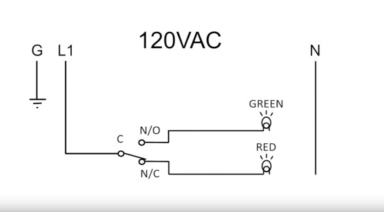
Logic of microswitch circuit: power comes in through C port and exits out the normally closed terminal; if switch is pressed, it is rerouted to normally open terminal, feeding power to a different source (in our case, the LEDs - as I was speculating before, NO connects to + for the LEDs); this is a clever mechanism as the lights would flash as the rotary motion has reached the end point (the switch acts as a trigger to register the value).
Problems left to work out: voltage! The 2A 125V notation on the switch is worrying - how is that much power even rerouted to the LEDs without burning them? I am speculating that the notation represents the limit rather than the power requirement, which would make all the sense in the world and would also mean that I could feed it 5V from the Arduino; an alternative would be to search for a similar microswitch configured especially for Arduino - could be tricky as circuit is built around the specific shape of this component.
=> Update: problem solved; after scouring some forums and consulting an electronics book, my suspicion that 125V was indeed the limit is confirmed. Last investigation before attempting to actually wire to Arduino is figuring out how the photocell matrix is laid out.
PHOTOCELL MATRIX:
I realised the photocells were arranged in a matrix format because of the keypads made to interface with the Arduino
4x rows, 3x columns
I need to investigate whether sensors can be arranged in a matrix and how to read the signals - I have limited experience with basic LED matrices only
PROGRESS UPDATE:
Switch and backlight LEDS working!!
After tinkering with the rotary system for a while, trying to figure out how it all works, I decided to re-assemble it and start testing with the Arduino. First step was to get the microswitch and LEDs working, because I needed light input to start figuring out the matrix (when in the dial casing, the photocells are covered unless the backlight is working). I fed 5V into the COM terminal, hooked up the No Connection port to a loose LED on a breadboard and the Not Open terminal to the LEDs inside the casing; as soon as I turned on the power, the breadboard LED was lit up; when the switch engaged, the breadboard LED went dark and the ones inside the casing lit up. Time to hook up the dial to the Arduino and hack interface with the matrix.
HACKING THE MATRIX:
I decided to start by looking at keypad matrices and how they work. I found a useful tutorial clearly explaining how matrix keypads work:
Keyboards use a matrix with the rows and columns made up of wires. Each key acts like a switch. When a key is pressed, a column wire makes contact with a row wire and completes a circuit. The keyboard controller detects this closed circuit and registers it as a key press. Here is a simple keyboard matrix:
Conceptual Matrix Circuit + Switch Open:

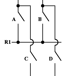
This keyboard only has 4 keys: A, B, C, and D. Each key has a unique grid location, much like points on a graph. Key A is at node C1R1, key B is at node C2R1, key C is at node C1R2, and key D is at node C2R2. In reality this is pretty useless which is why real keyboards use many more rows and columns.
In order to detect key presses, the keyboard controller will scan all columns, activating each one by one. When a column is activated, the controller detects which rows are "activated”.Now, let's say the the A key is pressed.
The matrix will look like this:
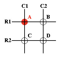
Key A corresponds to node C1R1. By going back to the circuit, we can see how C1R1 is detected.
(Schematics from https://www.dribin.org/dave/keyboard/one_html/)
Observations:
=> keypad logic seems quite straightforward; my photocell matrix has the same format as a standard phone keypad (3x col, 4x rows), but I still need to investigate whether the photoresistors can be treated the same as buttons in a keypad matrix. The PCB does not have any resistors (like a voltage divider circuit would). After a quick look at the chip on the main board in the telephone, I found this schematic:

The main board chip reads the matrix in the same row/column format as a keypad would. This means that there must be a way to compute this dial system and integration with Arduino is possible.
I tried experimenting with the photocell matrix by hooking it up to pins on the Arduino and using the Keypad library to try and read the rows and columns - this was not successful!!!, but to some extent; all keys seemed to return ‘1’, with some erratic readings of other, non-corresponding numbers that seemed random. The good part is that the Arduino can indeed communicate with the matrix; the bad part is that the results are erroneous.
I wired the pins directly to Arduino as one would a keypad. I am wondering now if resistors need to be added to create voltage dividers for the rows, or for both r/c.
Found this query on stack exchange from a person attempting the same thing:
https://electronics.stackexchange.com/questions/299879/reading-an-ldr-array-with-a-raspberry-pi?rq=1
They created a circuit diagram for the LDR matrix:

With no luck in finding many solutions to scanning matrices of analog sensors (most of the forum advice is for multiplexing LEDs - really confused about what code to write in order to identify resistance changes in this type of multiplexed array of analog sensors, I decided to focus on getting the other parts of the installation up and running and creating a contingency plan for the case in which the dial will not be functional.
Hacking the headset:
From what I can tell, the top part of the headset features a speaker and the bottom a microphone that can be interfaced with the Arduino. I won’t be using the microphone now, but it could have e interesting applications later.
I tried hooking it up to the DF Player mini in order to play some mp3 files through it. This worked!! The basis of the installation is working - there are alternatives to the dial, but the headset was essential.
Important headset notation: SPK1 on DFPlayer is GREEN headset wire, SPK2 is the RED one!
Switch button circuit to detect headset on/off:
Underneath the headset there is a spring system that puts weight on a small switch button when the headset is down, and releases it when the headset is lifted.
It only had two wires, so I used the Arduino’s internal pull-up on a digital pin in order to check whether it is being pressed or not. The experiment was successful. I can now automatically start a tune/ sound file with instructions when the headset is lifted, and halt all operations when it is down. !! I can also arrange for the phone to ring at certain time whilst the headset is down.
With the headset playback and position detection sorted, the rotary dial and ringer remain. For the ringer I’ll be needing to check how much voltage it needs to be fed in order to create sound - I could then use a relay with an AC power source to switch it on when I want it to ring.
Reflections on the dial issue and potential solutions:
For the dial problem, I will continue to try and debug it (hopefully someone at the Hatchlab may provide some info on how to scan this kind of matrix), but I have also created a contingency plan due to time restriction - if I will not be able to get number readings from the dial in time for the show, I will be laser cutting an extra layer for the front of the phone (where the dial sits) and fit it with an Arduino keypad of 4x3 similar to the dial. In hindsight, I feel like obtaining a phone with push buttons might have been a much much easier alternative. Initial tests with an old pulse-based dial worked splendidly, but unfortunately that phone is no longer available to me and I don’t know where to find an authentic 70s/80s phone apart from keeping an eye out at vintage sales.. who would have thought that an interface that is more new, even computational would pose more problems!
Apart from interfacing with the Arduino keypad rather than the original dial, I could also focus on the sound aspect of the installation (either just make the phone ring intermittently and have the installation be available only like that, when the phone “chooses” to call - ideally I would have liked to also have user input in addition to this. I can detect when a key, any key is pressed at the moment, but cannot pinpoint the specific key, which poses problems to my initial idea of having the user “call” a celestial body by inputting their coordinates or code number. Hacking the Matrix - continuation
From online forum questions, I’ve been able to glean that the matrix that I am dealing with is an array of photoresistors arranged in the format of a multiplexed switch matrix. I am still at a loss about how to approach writing my own code for this. Unfortunately, even with the help of the lab assistants, I was unable to make the dial work.
REFLECTION :: WORKAROUNDS & TIME RESTRICTIONS: I decided to implement a keyboard easily interfaced with the Arduino and modify the design of the phone a little bit - this allows for ease of use so I can focus on the visuals and the overall feeling of the piece in the remaining time. In the end, I would say it was a successful workaround that allowed for achieving a similar effect - I would have still liked to implement the tangible feeling of the dial, however this will be reserved for a secondary iteration due to time restrictions. I will also limit the first iteration to a “speed dial” system, using only single-key input, as tinkering around with the phone and reverse-engineering the way it works, as good a technical exercise as it is, has sucked up too large of a time component; I need to move on with the technical aspect now so that I can focus on creating the visual and sound elements and making sure they work together with the interface.
VISUALS AND SOUND:
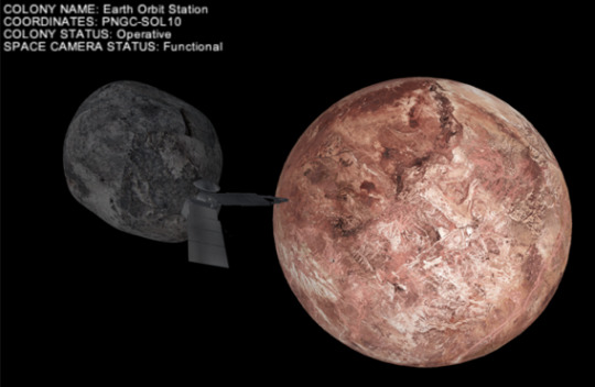
Creating the visuals was an interesting exercise in programming in 3D using Processing; the process really helped me better understand how to create and import 3D models, assemble a scene, wrap textures on an object, work with text in 3D space and create an overall feeling for a scene. The implemented sounds are planetary data sonification samples released into the public domain by NASA - further planned developments for the project include exploring my own data sonification system and experimenting with generative planet objects.
0 notes