#esp8266 arduino ide
Explore tagged Tumblr posts
Visit Tumblr Blog
Explore Tumblr blogs with no restrictions, modern design and the best experience.
Last Seen Tumblr Blogs


Fun Fact
Users from the US are the majority of Tumblr visitors.
Text
The ESP32 is a development board developed by Espressif systems. It can be programmed using Arduino IDE and ESP-IDF. It has higher processing power than ESP8266 but it is more costly and bigger in physical dimension than ESP8266. It has a built in Bluetooth module and CAN protocol and SRAM. It has 36 GPIO Pins with a CPU clock of 160MHz. It has 12-bit ADC onboard and supports CAN, UART, I2C and I2S. It can be used in prototyping IoT products, Low power Battery operated application, small range networking projects, and with the projects which require many Input Output Pins and Wi-Fi and Bluetooth connectivity.
6 notes
·
View notes
Text
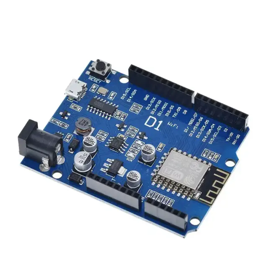
Wemos D1 Wifi Dev Board for Esp8266 IOT Module Online price is 10 units MOQ. Specification: Based on ESP-8266EX Compatible with Arduino,can be program by arduino ide. I/O Pin:11pcs Working Voltage:3.3V Input:7-24V Flash:4MB SRAM:32KB DRAM:80KB Clock Frequency:80MHz/160Mhz Network:802.11b/g/n Other development board you may interest: Interested with much more quantity,contact us to talk price.Know more about company site here. Read the full article
1 note
·
View note
Text
Getting Started with Embedded Systems Programming

Embedded systems programming is the backbone of modern electronics. From smartwatches to washing machines, embedded systems power the intelligent functions of countless everyday devices. This guide will introduce you to the basics of embedded programming, key tools, and how to begin building your own embedded applications.
What is an Embedded System?
An embedded system is a computer integrated into a larger system or device, performing dedicated functions. Unlike general-purpose computers, embedded systems are designed for specific tasks, often with constraints on power, memory, and processing.
Examples of Embedded Systems:
Microcontrollers in home appliances
Sensor-based devices (e.g., temperature sensors, motion detectors)
Medical equipment
Automotive control systems
IoT (Internet of Things) gadgets
Core Components of an Embedded System
Microcontroller or Microprocessor: The brain of the embedded system (e.g., Arduino, STM32, ESP32).
Memory: RAM and ROM to store instructions and data.
Input/Output Interfaces: Connects to sensors, displays, motors, and communication modules.
Software: Custom firmware developed for specific functions, typically in C or C++.
Popular Programming Languages
C: Most widely used due to its efficiency and low-level hardware access.
C++: Used when object-oriented design is required.
Assembly: For highly optimized or time-critical routines.
MicroPython: Python for microcontrollers (e.g., ESP8266, Micro:bit).
Getting Started with Embedded Programming
Select Your Platform:
Beginners: Arduino (easy setup, wide community support)
Advanced: STM32, Raspberry Pi Pico, ESP32
Set Up Your Development Environment:
Install IDEs like Arduino IDE, PlatformIO, STM32CubeIDE
Download necessary drivers and board support packages
Write and Upload Code: Create simple programs like blinking an LED, then expand to sensors, displays, and communication modules.
Example: Blink an LED with Arduino
void setup() { pinMode(13, OUTPUT); // Set pin 13 as output } void loop() { digitalWrite(13, HIGH); // Turn LED on delay(1000); // Wait for 1 second digitalWrite(13, LOW); // Turn LED off delay(1000); // Wait for 1 second }
Tools and Debugging
Serial Monitor: For real-time debugging and logging.
Oscilloscope & Logic Analyzer: For electrical signal inspection.
In-Circuit Debuggers: Like JTAG or ST-Link for low-level debugging.
Best Practices
Write modular and readable code.
Use debouncing for physical inputs like buttons.
Handle memory carefully to avoid overflows.
Optimize power usage in battery-powered devices.
Conclusion
Embedded systems programming is both fun and powerful, offering endless possibilities for innovation in hardware and software. Whether you’re building a home automation project or diving into the world of IoT, understanding the basics of embedded programming gives you the foundation to create smart, responsive devices.
0 notes
Text
MAX30100 am Arduino: Blutsauerstoff und Herzfrequenz messen leicht gemacht

Mit dem MAX30100 steht ein kompakter Sensor zur Verfügung, der sowohl die Herzfrequenz als auch den Blutsauerstoffgehalt (SpO₂) messen kann – ideal für einfache Gesundheits- und Fitnessprojekte mit dem Arduino. Ob die Werte dabei wirklich zuverlässig sind, schauen wir uns in diesem Beitrag genauer an. Ich zeige dir, wie du das MAX30100 Breakout Board anschließt, die Messwerte ausliest und sie im seriellen Monitor anzeigst. Die Kommunikation erfolgt über I²C, und dank der integrierten Energiesparfunktionen eignet sich der Sensor auch für batteriebetriebene Projekte.

MAX30100 Herfrequenz und Blutsauerstoff Sensor am Arduino Einen ähnlichen Sensor habe ich bereits im Beitrag „Arduino Lektion 79: Herzschlag-Pulssensor“ vorgestellt. Damals ging es um einen einfachen Herzschlagsensor, der per Infrarotlicht den Puls erkennen konnte. Der MAX30100 geht jedoch einen Schritt weiter: Er kombiniert Puls- und SpO₂-Messung in einem einzigen Modul und bietet damit deutlich mehr Möglichkeiten für eigene Projekte.
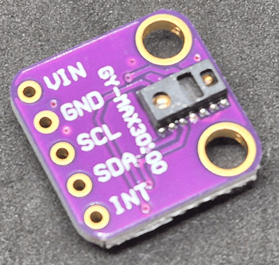
Vorderseite MAX30100 Herzfrequenz & Blutsauerstoff Sensor
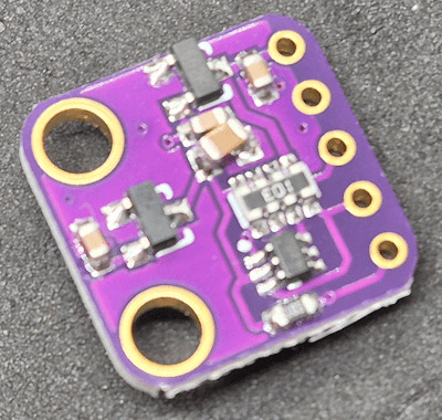
Rückseite des MAX30100 Sensors Hinweis: Der MAX30100 ist ein Sensor für den Hobby- und DIY-Bereich und nicht für den medizinischen Einsatz geeignet. Die gemessenen Werte können Anhaltspunkte liefern, ersetzen jedoch keinesfalls eine ärztliche Untersuchung oder professionelle Überwachung. Medizinisch zugelassene Geräte aus der Apotheke oder dem Sanitätshaus unterliegen strengen Normen und regelmäßigen technischen Prüfungen – etwas, das wir im Hobbybereich nicht leisten können. Nutze den Sensor daher ausschließlich für experimentelle oder edukative Zwecke.
Vielseitige Einsatzmöglichkeiten des MAX30100
Der MAX30100 eignet sich hervorragend für Projekte rund um die Überwachung von Vitalwerten, etwa in DIY-Fitness-Trackern, Schlafüberwachungen oder einfachen medizinischen Anwendungen im Hobbybereich. Durch seine kompakte Bauweise lässt sich der Sensor gut in tragbare Geräte integrieren. Neben dem Arduino ist der MAX30100 auch kompatibel mit Mikrocontrollern wie dem ESP32 oder ESP8266 sowie mit dem Raspberry Pi. Dank der standardisierten I²C-Schnittstelle ist die Anbindung an unterschiedliche Plattformen unkompliziert – ganz gleich, ob du mit der Arduino IDE, MicroPython oder Python arbeitest. Damit ist der Sensor eine ausgezeichnete Wahl für eine Vielzahl von Elektronikprojekten, bei denen es auf Puls- und Sauerstoffsättigungsmessung ankommt.
Technische Daten des MAX30100 Sensors
Bevor wir den Sensor in Betrieb nehmen, lohnt sich ein kurzer Blick auf die technischen Eckdaten. Der MAX30100 kombiniert einen Pulssensor und einen SpO₂-Sensor in einem kompakten Modul und ist für den Betrieb an Mikrocontrollern wie dem Arduino bestens geeignet. Die folgende Tabelle gibt einen Überblick über die wichtigsten Spezifikationen: EigenschaftWert / BeschreibungVersorgungsspannung3,3 VKommunikationI²C (Adresse: 0x57)MessfunktionenHerzfrequenz und Blutsauerstoffsättigung (SpO₂)LED-TypenRote LED und Infrarot-LEDAbtastrateProgrammierbarLED-StromProgrammierbar für EnergieeinsparungStandby-StromSehr niedrig (ultra-low current)Abmessungenca. 14 × 14 × 3,9 mm Der Sensor ist ideal für tragbare Projekte geeignet und lässt sich durch die I²C-Schnittstelle unkompliziert integrieren – auch in bestehende Schaltungen.
Bezug und Lieferumfang des MAX30100
Den Sensor bekommst du recht günstig auf Aliexpress.com und ebay.de. In meinem Fall habe ich mir diesen bei ebay.de für 5,92 € inkl. Versandkosten* geholt. Hinweis von mir: Die mit einem Sternchen (*) markierten Links sind Affiliate-Links. Wenn du über diese Links einkaufst, erhalte ich eine kleine Provision, die dazu beiträgt, diesen Blog zu unterstützen. Der Preis für dich bleibt dabei unverändert. Vielen Dank für deine Unterstützung!
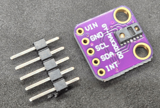
Lieferumfang des MAX30100 Sensors
Überblick über den MAX30100 – Aufbau und Pinbelegung
Damit du den MAX30100 korrekt anschließen und in deine Schaltung integrieren kannst, werfen wir einen genaueren Blick auf den Aufbau des Breakout-Boards. Auf dem folgenden Bild habe ich die wichtigsten Komponenten und Pins für dich beschriftet:
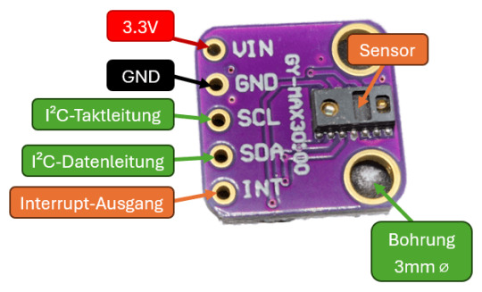
Aufbau & Pinout des MAX30100 Sensors Beschreibung der markierten Elemente: - VIN – Versorgungsspannung (3,3 V) - GND – Masse - SCL – I²C-Taktleitung - SDA – I²C-Datenleitung - INT – Interrupt-Ausgang (optional, wird in einfachen Projekten oft nicht verwendet) - MAX30100 Chip – Der eigentliche Sensor, der rote und IR-LEDs sowie den Fotodetektor enthält - Status-LED – Zeigt an, ob der Sensor aktiv ist (je nach Board vorhanden) Achte darauf, dass du den Sensor nicht direkt mit 5 V versorgst, da er nur mit 3,3 V betrieben werden darf. Manche Breakout-Boards haben zwar einen Spannungsregler integriert – überprüfe das aber unbedingt vorher im Datenblatt deines Moduls.
Schaltung: MAX30100 am Arduino UNO R3 anschließen
Für den ersten Test schließen wir den MAX30100 Sensor an einen Arduino UNO R3 an. Die gemessenen Werte – Puls und Blutsauerstoff – lassen sich bequem über den seriellen Monitor der Arduino IDE ausgeben oder alternativ mit dem seriellen Plotter grafisch als Liniendiagramm darstellen. Benötigte Komponenten - 1 × Arduino UNO R3* - 1 × MAX30100* - 1 × 170-Pin Mini-Breadboard* - 4 × Breadboardkabel* männlich–männlich, 10 cm (Farben: Rot, Schwarz, Gelb, Grün) Verdrahtung

Schaltung - Arduino UNO R3 mit MAX30100 Sensor MAX30100 PinFunktionArduino UNO R3 PinKabel-FarbeVINVersorgung 3,3 V3.3VRotGNDMasseGNDSchwarzSDAI²C DatenleitungA4 (SDA)GelbSCLI²C TaktleitungA5 (SCL)Grün
Vorbereitung: Leeres Programm zur Rücksetzung der Pins hochladen
Bevor wir den MAX30100 anschließen und mit der eigentlichen Programmierung beginnen, empfehle ich einen kleinen, aber hilfreichen Zwischenschritt: Lade zunächst ein leeres Programm auf deinen Arduino, um sicherzustellen, dass alle Pins wieder auf ihren Standardzustand (Input) zurückgesetzt werden. Gerade wenn zuvor ein anderes Sketch geladen war, in dem Pins als Ausgänge oder mit bestimmten Pegeln konfiguriert wurden, kann das bei sensiblen Sensoren wie dem MAX30100 zu unerwünschtem Verhalten oder sogar Schäden führen. void setup() { // put your setup code here, to run once: } void loop() { // put your main code here, to run repeatedly: }
Bibliothek für den MAX30100 installieren
Für die Programmierung des MAX30100-Sensors findest du im Bibliotheksverwalter der Arduino IDE zahlreiche Bibliotheken. Ich verwende in diesem Beitrag die einfach gehaltene Bibliothek aus dem GitHub-Repository oxullo/Arduino-MAX30100. Diese Bibliothek ist schlank, verständlich aufgebaut und bringt zudem einige Beispielsketches mit, die wir fast direkt verwenden können – ideal für den Einstieg in die Arbeit mit dem Sensor.
Auslesen der Werte für Herzfrequenz und Blutsauerstoff in der Arduino IDE
Starten wir zunächst mit einem einfachen Beispiel aus der Bibliothek von oxullo für den MAX30100 Sensor. Hier wird auf dem seriellen Monitor die Daten ausgegeben. Jedoch möchte ich diese im seriellen Plotter ausgeben.
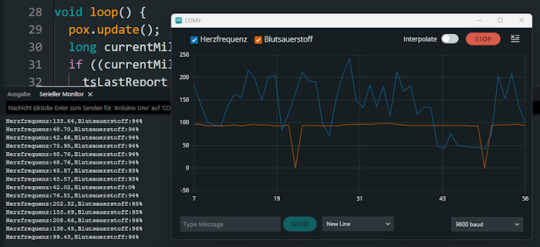
Ausgabe der Herzfrequenz & Blutsauerstoff des MAX30100 Sensors in der Arduino IDE Beispiel Programm für den MAX30100 Sensor am Arduino // Inkludiere die benötigten Bibliotheken für I²C-Kommunikation und den MAX30100-Sensor #include #include "MAX30100_PulseOximeter.h" // Intervall für die Ausgabe der Messwerte (in Millisekunden) #define REPORTING_PERIOD_MS 1000 // Erzeuge ein Objekt für den Sensor PulseOximeter pox; // Variable, um den Zeitpunkt der letzten Ausgabe zu speichern uint32_t tsLastReport = 0; // Diese Funktion wird aufgerufen, wenn ein Herzschlag erkannt wird void onBeatDetected() { Serial.println("Beat!"); // Ausgabe im seriellen Monitor } void setup() { // Initialisiere die I²C-Schnittstelle Wire.begin(); // Starte die serielle Kommunikation mit 9600 Baud Serial.begin(9600); Serial.print("Initialisierung des Sensors MAX30100"); // Versuche, den Sensor zu starten if (!pox.begin()) { Serial.println("Sensor wurde nicht gefunden!"); Serial.println("Überprüfe die Verkabelung!"); // Endlosschleife, wenn der Sensor nicht erkannt wurde while (true) { } } // Setze den LED-Strom der Infrarot-LED (mögliche Werte siehe Bibliothek) pox.setIRLedCurrent(MAX30100_LED_CURR_7_6MA); // Optional: Reaktion auf Herzschlag registrieren // pox.setOnBeatDetectedCallback(onBeatDetected); } void loop() { // Aktualisiere die Sensorwerte intern (wichtig für die kontinuierliche Messung) pox.update(); // Aktuelle Zeit in Millisekunden long currentMillis = millis(); // Überprüfe, ob das Intervall seit der letzten Ausgabe erreicht ist if ((currentMillis - tsLastReport) > REPORTING_PERIOD_MS) { tsLastReport = currentMillis; // Ausgabe der gemessenen Herzfrequenz und Sauerstoffsättigung Serial.print("Herzfrequenz:"); Serial.print(pox.getHeartRate()); Serial.print(","); Serial.print("Blutsauerstoff:"); Serial.print(pox.getSpO2()); Serial.println("%"); } } Hinweise: - Die Funktion pox.update(); muss regelmäßig im Loop aufgerufen werden, da dort die Messung verarbeitet wird. - Die Ausgabe erfolgt einmal pro Sekunde durch die REPORTING_PERIOD_MS Definition. - Die onBeatDetected()-Callback-Funktion ist derzeit auskommentiert, kann aber bei Bedarf aktiviert werden, um Herzschläge zusätzlich zu signalisieren. Beim ausführen des Codes sind zwei Fehler aufgetreten zum einen ist der Blutsauerstoff öfters auf 0 gesunken und auch mal > 100% beides sind fälle welche man durch eine If-Bedingung entfernen kann da dieses nicht eintreffen kann. // Lese aktuelle Messwerte vom Sensor aus float herzfrequenz = pox.getHeartRate(); // Herzfrequenz in bpm (beats per minute) int blutsauerstoff = pox.getSpO2(); // Sauerstoffsättigung in Prozent // Überprüfe, ob der Wert für Blutsauerstoff realistisch ist // Gültige Werte liegen typischerweise zwischen 70 und 100 % // Werte 100 treten bei fehlerhafter Messung auf und sollen ignoriert werden if (blutsauerstoff > 0 && blutsauerstoff - einen - einen - ein - vier - vier - ein REPORTING_PERIOD_MS) { tsLastReport = currentMillis; // Werte vom Sensor abfragen int herzfrequenz = round(pox.getHeartRate()); // Herzfrequenz auf ganze Zahl runden int blutsauerstoff = pox.getSpO2(); // SpO₂-Wert als Integer // Nur gültige Werte anzeigen (SpO₂ muss im Bereich 1–100% liegen) if (blutsauerstoff > 0 && blutsauerstoff Read the full article
0 notes
Text
Wemos D1 Mini Pinout: Master the ESP8266 Mini Pinout for Your Next IoT Project
If you're exploring IoT projects, the Wemos D1 Mini is a tiny but powerful board you’ll want in your toolkit. Built around the reliable ESP8266 chip, it combines Wi-Fi connectivity with a compact, breadboard-friendly design. This makes it perfect for projects like smart home automation, DIY gadgets, or even experimenting with sensors and actuators.
One of the key things you need to know is the Wemos D1 Mini pinout, as it lays the foundation for what your board can do. With 11 GPIO pins, power options (3.3V and 5V), and essential pins like TX, RX, and A0, the Wemos D1 Mini offers plenty of flexibility for small-scale IoT projects. The ESP8266 Mini pinout adds another layer of versatility, making it easy to work with various modules and devices while maintaining compatibility with standard Arduino IDE libraries.
Key pin highlights:
GPIO Pins: Ideal for connecting sensors, LEDs, relays, and more.
A0 Pin: Used for analog inputs, with a range of 0-3.3V.
TX/RX Pins: Essential for serial communication with other devices.
Power Pins: Supports both 5V and 3.3V power supplies for flexibility.
Whether you’re working on a Wi-Fi-enabled weather station, a smart light controller, or a quirky robot, understanding the Wemos D1 Mini pinout and ESP8266 Mini pinout is key to maximizing your board's potential.
Ready to dive deeper? Check out our detailed guide on pinouts here and get started with your next IoT adventure today!
#WemosD1Mini#WemosD1MiniPinout#D1MiniPinout#ESP8266Pinout#WemosPinoutGuide#Microcontroller#IoTDevelopment#ArduinoProjects#ESP8266Projects#WemosProjects#WemosD1MiniGuide#IoTDevices#EmbeddedSystems#WemosTutorial#PinoutDiagram
0 notes
Text
Arduino Projects
The Arduino platform, which is based on microcontrollers, makes it easier to create and execute electronic projects. A physical programmable circuit board serves as the hardware component, and an Integrated Development Environment, or IDE, is the software that is used to write and upload code to the board. You can select the board that best fits your project requirements from a range of options, including Arduino Uno, Mega, and Nano.
Top Arduino Projects to Try
Automation System for Smart Homes
Use an automation system driven by Arduino to turn your house into a smart home. Voice commands or your smartphone can be used to operate lights, fans, and other appliances. You may increase the efficiency and intelligence of your house by incorporating sensors and modules like the ESP8266 Wi-Fi module or the HC-05 Bluetooth module.
The weather station
To keep an eye on the temperature, humidity, and air pressure, build your own weather station. In addition to improving your knowledge of sensors, this project offers real-time data collecting, which may be helpful for practical or instructional reasons.
Line-Following Robot
An excellent project to start learning robotics is a line-following robot. The robot detects and follows a predetermined course using infrared sensors. The fundamentals of sensor integration and motor control are covered in this project.
Arduino-Based LED Cube
Programming patterns and animations into a 3D matrix of LEDs creates the visually beautiful LED cube. This project is ideal for teaching 3D coordinate systems and multiplexing.
Smart Plant Watering System
A smart watering system that employs soil moisture sensors to water your plants automatically when necessary will help you keep them healthy. For people who travel regularly or are busy, this project is ideal.
Gesture-Controlled Robot
Create a robot that can be directed by gestures to advance robotics. Simple hand gestures can be used to control the robot's motions utilizing an accelerometer and two Arduino boards.
Arduino projects are a great way to realize your imaginative ideas and gain useful programming and electronics skills. Whether you're a professional, student, or enthusiast, Arduino offers countless opportunities. Use this strong and flexible platform to dive in, try things out, and see your ideas come to life!
To know more, click here.
0 notes
Text
DIY Smart Home Energy Monitor with ESP32 and Home Assistant
Introduction
Managing energy consumption is a great way to reduce electricity costs and contribute to environmental sustainability. With the help of IoT, you can monitor energy usage in real-time, right from your smartphone. In this guide, we’ll build a Smart Home Energy Monitor using an ESP32 microcontroller, current and voltage sensors (like the ACS712 or SCT-013), and the MQTT protocol for data transmission. This data will be accessible on a mobile app via Home Assistant, allowing you to keep track of energy usage and optimize it effectively.
Project Overview
Objectives
Monitor power consumption in real-time for home appliances.
Display energy usage on a mobile app using MQTT and Home Assistant.
Analyze data over time to make informed decisions about energy usage.
Key Components
ESP32 (or ESP8266) microcontroller: For reading sensor data and connecting to Wi-Fi.
Current Sensor (SCT-013 or ACS712): For measuring current drawn by appliances.
Voltage Sensor: Optional, but adds more accuracy if you want to measure precise power usage.
MQTT Protocol: To send data to Home Assistant for real-time monitoring.
Home Assistant: A home automation platform to display and analyze data.
Part 1: Setting Up the Components
1. ESP32 or ESP8266 Microcontroller
Choose either the ESP32 or ESP8266 microcontroller. The ESP32 has more features and is preferred, but either will work.
Connect the ESP32 to your computer using a USB cable to program it.
2. Current Sensor (SCT-013 or ACS712)
SCT-013 is a non-invasive sensor that clamps around a wire to measure the AC current flowing through it.
ACS712 is a current sensor that can measure both AC and DC current but requires direct connection to the wire, so exercise caution with high voltage.
Wiring for SCT-013
Connect the SCT-013 sensor’s output to an analog input pin on the ESP32.
If you’re using SCT-013 with ESP8266, you’ll need an analog-to-digital converter (ADC) module since the ESP8266 has only one analog input pin with limited resolution.
Wiring for ACS712
Connect the VCC pin to the 3.3V or 5V pin on the ESP32.
Connect the OUT pin to an analog input pin on the ESP32.
Connect the GND pin to the ground (GND) on the ESP32.
3. Voltage Sensor (Optional)
A voltage sensor can be added to measure the actual voltage if you want to calculate power more accurately.
Connect the sensor’s VCC to the 3.3V on ESP32, GND to ground, and OUT to an analog input.
Part 2: Coding the ESP32 for Data Acquisition and Transmission
1. Install the Required Libraries
Make sure you have the following libraries installed in your Arduino IDE:
ESP32 or ESP8266 board support (depending on your microcontroller)
PubSubClient library for MQTT communication
WiFi library for connecting to your Wi-Fi network
2. Set Up the Code
Here’s the code to:
Read values from the current sensor.
Calculate power consumption (voltage x current if you have a voltage sensor, or assume constant voltage).
Publish data to an MQTT broker.
#include <WiFi.h> #include <PubSubClient.h>
// Wi-Fi and MQTT Broker Settings const char* ssid = "YOUR_SSID"; const char* password = "YOUR_PASSWORD"; const char* mqtt_server = "YOUR_MQTT_BROKER_IP";
// MQTT topics const char* topicPower = "home/energy_monitor/power";
WiFiClient espClient; PubSubClient client(espClient);
// Sensor parameters const int sensorPin = 34; // Analog pin for sensor (ESP32) const float voltageCalibration = 230.0; // Voltage in volts (modify as per your region) const float sensorCalibration = 0.185; // Calibration constant for ACS712 sensor
void setup() { Serial.begin(115200); setup_wifi(); client.setServer(mqtt_server, 1883); }
void setup_wifi() { delay(10); Serial.println("Connecting to WiFi..."); WiFi.begin(ssid, password); while (WiFi.status() != WL_CONNECTED) { delay(500);
Serial.print("."); } Serial.println("Connected to WiFi."); }
void reconnect() { while (!client.connected()) { Serial.print("Connecting to MQTT..."); if (client.connect("ESP32Client")) { Serial.println("Connected."); } else { delay(5000); } } }
void loop() { if (!client.connected()) { reconnect(); } client.loop();
// Read sensor data int rawValue = analogRead(sensorPin); float current = rawValue * sensorCalibration; // Adjust based on sensor
// Calculate power float power = voltageCalibration * current; // Simple power calculation (P=VI)
// Publish data to MQTT String powerStr = String(power); client.publish(topicPower, powerStr.c_str()); Serial.print("Power: "); Serial.println(power); delay(2000); // Send data every 2 seconds }
3. Upload Code
Connect your ESP32 to your computer.
Select the correct board and port in the Arduino IDE.
Upload the code to the ESP32.
Part 3: Setting Up Home Assistant and MQTT Broker
1. Set Up MQTT Broker
If you don’t have an MQTT broker, you can use Mosquitto on your local network or use an online MQTT service like HiveMQ.
Install Mosquitto on a Raspberry Pi or a computer running Home Assistant.
Configure Mosquitto by setting a username and password for secure access.
2. Configure Home Assistant
In Home Assistant, you’ll add the MQTT integration to receive data from the ESP32.
Go to Settings > Integrations and search for MQTT.
Enter your MQTT broker details and save the configuration.
3. Add a Sensor in Home Assistant
In your Home Assistant configuration file (configuration.yaml), add the following entry to display power data:sensor: - platform: mqtt name: "Home Power Consumption" state_topic: "home/energy_monitor/power" unit_of_measurement: "W" value_template: "{{ value | float }}"
Restart Home Assistant to apply changes.
You should now see a Home Power Consumption sensor in your Home Assistant dashboard.
Part 4: Testing and Using the Energy Monitor
Power on your ESP32 and ensure it’s connected to Wi-Fi.
Open Home Assistant, where you should see the real-time data of power consumption.
Monitor the data over time and optimize energy usage based on the data.
Conclusion
With this DIY Smart Home Energy Monitor, you can track power usage across various appliances in your home. This project introduces core IoT concepts such as data acquisition, MQTT communication, and integration with Home Assistant. You can further expand this setup by adding more sensors or even automating appliances based on usage patterns.
#Tech4bizsolutions #SmartHome #EnergyMonitoring #ESP32Projects #HomeAssistant #IoTProjects #DIYElectronics #MQTTProtocol #SmartHomeAutomation #PowerConsumption #EnergyEfficiency #ESP8266Projects #IoTDevelopment #HomeAutomationIdeas #TechDIY #SustainableLiving
0 notes
Text
Getting Started with Embedded Programming: Tools and Techniques
Embedded programming is an exciting field that combines hardware and software to create systems that control various devices and processes. From simple microcontrollers in household appliances to complex systems in automobiles and medical devices, embedded programming plays a vital role in modern technology. If you’re looking to dive into embedded programming, this guide will outline essential tools and techniques to help you get started.

Understanding Embedded Programming
At its core, embedded programming involves writing software that runs on embedded systems—computers designed to perform dedicated functions within larger systems. Unlike traditional programming, which often runs on general-purpose computers, embedded programming requires a deep understanding of hardware constraints, real-time performance requirements, and low-level programming.
Essential Tools for Embedded Programming
Microcontrollers and Development Boards
Arduino: A popular platform for beginners, Arduino boards come with an integrated development environment (IDE) and a user-friendly programming language based on C/C++. The vast community support and numerous libraries make it easy to get started.
Raspberry Pi: Although primarily a single-board computer, Raspberry Pi can be used for embedded programming projects, especially those requiring more computational power. It supports various programming languages and operating systems.
ESP8266/ESP32: These Wi-Fi-enabled microcontrollers are ideal for IoT projects. They are programmable using the Arduino IDE or the Espressif IDF and offer great features for wireless applications.
Development Environments and IDEs
Arduino IDE: Specifically designed for Arduino programming, this IDE simplifies the process of writing and uploading code to the board.
PlatformIO: An open-source ecosystem for IoT development, PlatformIO supports multiple boards and frameworks, providing advanced features like libraries and debugging tools.
Keil uVision: A popular IDE for ARM microcontrollers, offering a comprehensive development environment, including simulation and debugging capabilities.
Eclipse with Embedded Plugins: Eclipse can be customized with plugins for embedded development, supporting various toolchains and microcontrollers.
Compilers and Toolchains
GCC (GNU Compiler Collection): Widely used for compiling C and C++ code for embedded systems. It supports various microcontroller architectures and is essential for low-level programming.
ARM Toolchain: A collection of tools used to develop applications for ARM-based microcontrollers. It includes a compiler, assembler, and linker, providing everything needed for embedded development.
Debugging Tools
JTAG/SWD Debuggers: Hardware debuggers like J-Link or ST-Link provide a means to debug embedded systems at the hardware level, allowing for real-time code execution and monitoring.
Serial Monitors: Tools that enable communication between your computer and the microcontroller via serial ports. They are useful for debugging and monitoring output during development.
Techniques for Embedded Programming
Start with a Simple Project Begin with a basic project that interests you, such as blinking an LED or reading a sensor. This hands-on experience will help you understand the fundamentals of embedded programming and familiarize you with the tools.
Learn C/C++ Basics Most embedded systems are programmed in C or C++, so having a strong grasp of these languages is essential. Focus on key concepts such as data types, control structures, and pointers, as these are frequently used in embedded programming.
Understand Hardware Basics Familiarize yourself with the hardware you are working with, including pin configurations, voltage levels, and peripheral interfaces (like I2C, SPI, UART). Knowing how to interact with the hardware is crucial for successful embedded programming.
Utilize Libraries and Frameworks Take advantage of existing libraries and frameworks to simplify your development process. Libraries can provide pre-written code for common functions, such as controlling motors or reading sensors, allowing you to focus on the logic of your application.
Implement Real-Time Operating Systems (RTOS) For more complex projects, consider using an RTOS to manage multitasking and timing constraints. An RTOS helps in scheduling tasks, ensuring that your application meets real-time requirements.
Practice Debugging and Testing Develop good debugging habits by regularly testing your code and using debugging tools. Learn to analyze errors, use breakpoints, and monitor variables during execution. Rigorous testing will ensure that your embedded application functions as intended.
Expanding Your Knowledge
Online Courses and Tutorials: Platforms like Coursera, Udacity, and edX offer various courses in embedded systems and programming. These courses can provide structured learning and hands-on projects.
Books and Resources: Consider reading books like "Programming Embedded Systems in C and C++" by Michael Barr or "The Definitive Guide to ARM Cortex-M3 and Cortex-M4 Processors" by Joseph Yiu for deeper insights.
Join Communities and Forums: Engaging with online communities such as Arduino forums, Raspberry Pi forums, or Stack Overflow can provide support and inspiration. These platforms are valuable for asking questions and sharing your projects.
Conclusion
Getting started with embedded programming can be both challenging and rewarding. By leveraging the right tools and techniques, you can develop your skills and create innovative projects that bridge the gap between hardware and software. Whether you aim to build IoT devices, control robotics, or develop smart applications, the world of embedded programming offers endless possibilities. So, gather your tools, start coding, and unleash your creativity in this fascinating field!
0 notes
Text
Introducing the NODEMCU MEGA WIFI R3!
Take your projects to the next level with the NODEMCU MEGA WIFI R3. This powerful development board combines the versatility of the Arduino MEGA with the connectivity of the ESP8266, making it perfect for a wide range of applications.
Integrated Design: Combines the ATmega2560 microcontroller and ESP8266 Wi-Fi IC on a single board, offering seamless integration and enhanced functionality.
High Memory Capacity: Equipped with 32Mb of flash memory, providing ample space for your complex projects.
Versatile Connectivity: Features a CH340G USB-TTL converter, ensuring reliable communication between your board and computer.
Flexible Operation: Components can be configured to work together or independently, giving you the flexibility to tailor the board to your specific needs.
Ideal for IoT Projects: Perfect for home automation, robotics, and other IoT applications, thanks to its robust Wi-Fi capabilities.
Whether you’re a hobbyist or a professional, the NODEMCU MEGA WIFI R3 is designed to meet your needs and exceed your expectations.
Product Specifications:
Microcontroller: ATmega2560
Wi-Fi IC: ESP8266
Memory: 32Mb flash
USB-TTL Converter: CH340G
Compatibility: Compatible with Arduino IDE
Unlock the full potential of your projects with the NODEMCU MEGA WIFI R3. Get yours today and start creating!
For more details or to place an order, visit our website or call us at +8801740298319.
Click here to purchase the product: https://dhakarobotics.com/.../1038-nodemcu-mega-wifi-r3.../
visit our website: https://dhakarobotics.com/

#NodeMCU#MEGAWIFI#Arduino#IoT#SmartProjects#WiFiBoard#Electronics#DIYTech#Robotics#HomeAutomation#TechGadgets#MakerCommunity#STEM#TechEnthusiast#ElectronicsHobbyist#ArduinoProjects#TechDIY#GadgetLovers#Innovation#dhakarobotics
0 notes
Text
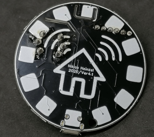
Ouija 8266
In 2021, I created this ESP8266 programmer that looks like a Ouija board planchette. You can attach an ESP-01 module, plug in an FTDI cable, and program the module from your computer using the Arduino IDE – then wear the programmer as an earring!

Here's the full write-up:
1 note
·
View note
Text
Mastering IoT Design: Building Smart Systems with ESP8266/ESP12, Arduino, MQTT, and Google Home Integration

The Internet of Things (IoT) has transformed the way we interact with devices and has opened up a world of possibilities for automation and remote control. In this blog post, we will explore the benefits of enrolling in the ESP8266/ESP12 IoT Design course, which offers a comprehensive learning experience in designing and developing IoT systems from scratch. We will highlight the career path and opportunities that await individuals skilled in IoT technologies.
The ESP8266/ESP12 IoT Design course offers a practical, hands-on approach to learning. Students will gain valuable insights into designing the hardware components of IoT devices and developing firmware using the Arduino Integrated Development Environment (IDE). Through interactive exercises, they will learn how to build and program smart devices that can be controlled remotely.
This course covers all major components of an IoT system, providing students with a holistic understanding of the entire ecosystem. They will learn to install and configure a cloud server, set up an MQTT broker within the cloud server, and deploy a Django web server. These skills are crucial for building scalable and secure IoT solutions. Students will also gain knowledge in designing user interfaces and integrating voice assistants such as Google Home for enhanced control and convenience.
By completing this course, students will acquire the skills to develop practical IoT applications that can be utilized in various settings. They will learn how to control equipment or electrical loads, operate garage doors, and create keyless entry systems using their smartphones. These applications can enhance convenience, security, and efficiency in homes, offices, and other environments. With their newfound knowledge, students can design and implement custom IoT solutions tailored to specific needs.
Professionals skilled in IoT technologies are in high demand across industries. By enrolling in the ESP8266/ESP12 IoT Design course, individuals can enhance their career prospects and open doors to new opportunities. IoT specialists can work as IoT developers, firmware engineers, IoT solution architects, or IoT consultants. Additionally, the versatility of the skills acquired in this course allows for entrepreneurship and product development, as students can leverage their knowledge to create marketable IoT products.
The IoT industry is continuously evolving, with new technologies and advancements emerging rapidly. By mastering IoT design principles and developing hands-on experience through this course, students will be well-equipped to adapt to the ever-changing landscape. They will have a solid foundation to explore emerging IoT platforms, protocols, and applications, ensuring they remain at the forefront of this dynamic field. Enrolling in the ESP8266/ESP12 IoT Design course is a valuable investment for anyone interested in IoT technology. With a practical, hands-on learning approach, students will acquire the skills to design, develop, and deploy IoT systems from the ground up. The comprehensive curriculum covers all essential components, including hardware design, firmware development, cloud server configuration, and Google Home integration. By mastering these skills, individuals can embark on a rewarding career path in IoT development, consulting, or entrepreneurship. Take the first step towards becoming an IoT expert by enrolling in the ESP8266/ESP12 IoT Design course today!

1 note
·
View note
Text
ESP8266 Wifi Module | Nodemcu ESP8266 for IoT Solution
The Internet of Things (IoT) is revolutionizing the way we interact with technology, making our lives smarter and more efficient. At the heart of this revolution is the ESP8266 WiFi module, a low-cost, powerful solution perfect for your IoT projects. Whether you're a hobbyist, a professional developer, or a business looking to integrate smart technology into your products, the ESP8266 WiFi module offers unmatched versatility and performance. Here's why you should consider buying the ESP8266 WiFi module and how the NodeMCU ESP8266 can be your gateway to a myriad of IoT solutions.
What is the ESP8266 WiFi Module?
The ESP8266 is a highly integrated chip designed for the needs of a new connected world. It offers a complete and self-contained WiFi networking solution, allowing it to either host the application or offload all WiFi networking functions from another application processor. With its low cost and high performance, the ESP8266 WiFi module has become a popular choice among IoT developers.
ESP8266 NodeMcu WiFi Development Board Features:-
It is based on ESP8266, integates GPIO, PWM, IIC, 1-Wire and ADC all in one board.
Power your developement in the fastest way combinating with NodeMCU Firmware!
USB-TTL included, plug&play
10 GPIO, every GPIO can be PWM, I2C, 1-wire
Open source IoT Platform
Easily Programmable
Low cost & Simple to Implement
WI-FI enabled
ESP8266 NodeMcu WiFi Development Board Applications:-
Home Appliances
Home Automation
Smart Plug and lights
Mesh Network
Industrial Wireless Control
Baby Monitors
IP Cameras
Sensor Networks
Wearable Electronics
Why Choose NodeMCU ESP8266 for Your IoT Projects?
Ease of Use: NodeMCU's integrated USB-to-serial interface and pre-flashed firmware allow for immediate programming and development.
Versatile Programming: You can program the NodeMCU using the Arduino IDE or NodeMCU’s native Lua scripting language, giving you flexibility in development.
Wide Community Support: As one of the most popular IoT development platforms, NodeMCU has extensive documentation and a large community, making it easier to find support and resources.
Cost-Effective: NodeMCU provides a highly cost-effective solution for IoT development, offering excellent value for money.
Rapid Prototyping: Its comprehensive feature set and ease of use make NodeMCU ideal for rapid prototyping and deployment of IoT solutions.
Conclusion
Purchase Your ESP8266 and NodeMCU ESP8266 Today!
Don't miss out on the opportunity to enhance your IoT projects with the best technology available. Purchase your ESP8266 WiFi module and NodeMCU ESP8266 development board today and join the growing community of IoT developers who are shaping the future of technology.
Innovation awaits at Campus Component, where you can buy genuine ESP8266 NodeMCU boards at competitive prices. Take the first step towards realizing your IoT dreams and explore the endless possibilities of connected devices. Order now and join the IoT revolution with Campus Component as your trusted partner.
0 notes
Text
Essential Embedded Software Development Tools for a Smooth Development Process
Embedded software development is a specialized field that requires a unique set of tools to ensure the smooth creation of software that runs on embedded systems, such as microcontrollers and microprocessors. These tools are essential for debugging, testing, and optimizing code for these resource-constrained environments. In this blog post, we’ll explore some of the key embedded software development tools that every developer should have in their toolbox.
Integrated Development Environments (IDEs)
IDEs are the central hub for embedded software development. They provide a comprehensive platform for writing, editing, compiling, and debugging code. Some popular IDEs for embedded development include:
Eclipse: An open-source IDE with a vast ecosystem of plugins, including many tailored for embedded development.
Keil MDK: A dedicated IDE for ARM-based microcontrollers.
IAR Embedded Workbench: A powerful toolchain for ARM, MSP430, and RISC-V processors.
PlatformIO: An open-source IDE that supports multiple platforms, including Arduino, ESP8266, and STM32.
Cross-Compilers
Cross-compilers are essential tools that allow you to write and compile code on a host machine while targeting a different architecture, like an ARM-based microcontroller. These compilers help optimize code for the target hardware. Popular cross-compilers include GCC (GNU Compiler Collection), ARM Keil, and IAR Embedded Workbench.
Debugging Tools
Debugging is a crucial aspect of embedded software development. Without the right tools, finding and fixing bugs can be a daunting task. Some of the tools used for debugging embedded systems are:
JTAG Debuggers: These hardware tools connect to your embedded system and enable you to halt program execution, inspect variables, and trace program flow.
Serial Debuggers: These are essential for debugging when using serial communication with your embedded system.
GDB (GNU Debugger): GDB is a popular open-source debugger that can be used with various IDEs and hardware debuggers.
Real-Time Operating Systems (RTOS)
Many embedded systems require real-time capabilities, and an RTOS is often the best way to achieve this. Popular RTOS options include FreeRTOS, Micrium uC/OS, and VxWorks. These operating systems help manage tasks, priorities, and resources in an embedded system.
Code Analysis and Profiling Tools
Code analysis and profiling tools are essential for optimizing code and identifying potential issues. Tools like Lint, Cppcheck, and Static Analysis Tools can help find code quality and security issues, while profiling tools like Gprof and Percepio Tracealyzer can help identify performance bottlenecks.
Version Control Systems
Effective version control is crucial for collaboration and code management. Tools like Git and SVN help keep track of code changes, facilitate collaboration, and provide a backup for your work.
Simulation Tools
Simulation tools allow you to test your embedded code on a host machine before deploying it to the target hardware. Tools like QEMU and Simulink can help you validate your code without the need for physical hardware.
Documentation and Collaboration Tools
Proper documentation is essential for understanding and maintaining embedded software. Tools like Doxygen can automatically generate documentation from code comments. Collaboration tools like Slack, Microsoft Teams, or even a simple Wiki can help teams work together efficiently.
Conclusion
Embedded software development can be a challenging but rewarding field. Having the right tools at your disposal can make the process much more manageable. Whether you are a beginner or an experienced developer, these tools can help streamline your development process, improve code quality, and ensure the reliability of your embedded systems. Make sure to choose the tools that best suit your project requirements and hardware platform for a successful embedded software development journey.
0 notes
Text
Sensor Digital de presión para medir la hermeticidad en cañerías de Gas con el celular
En Argentina, cuando el Gasista matriculado realiza una instalación nueva, la debe someter a una prueba de hermeticidad antes de aprobar la obra, para realizar esa prueba el gasista conecta un manómetro, con escala de 1 kg/cm² luego infla la cañería hasta llegar a una presión de 0,2 kg/cm², en una primera etapa las llaves de paso de los artefactos deben estar cerradas, se debe comprobar que la aguja del manómetro quede inmóvil durante 15 minutos, luego se repite la prueba pero con las llaves de paso de los artefactos abiertas, y los robinetes del artefacto cerrados.
La cañería se infla con aire, con un compresor o un inflador de bicicleta.
Un dato importante, la presión nominal del gas natural es de 20 gr/cm² y 28gr/cm² para el gas envasado, y la prueba de hermeticidad se haría a 200 gr/cm² que sería lo mismo que 0,2 kg/cm²
Esta es una foto del d1 mini con el sensor bmp280

//Código para quemar con el arduino ide:
#include <ESP8266WiFi.h>
#include <WiFiClient.h>
#include <Adafruit_BMP280.h>
// Cambia estos valores para conectarte a tu red Wi-Fi
const char* ssid = "cursodegas";
const char* password = "12345678";
// Crea un objeto BMP280
Adafruit_BMP280 bmp;
// Crea un objeto servidor
WiFiServer server(80);
// Variable para almacenar el tiempo de la última actualización
unsigned long lastUpdate = 0;
// Variable para almacenar la presión atmosférica local (en hPa)
float localPressure = 0.0;
void setup() {
// Inicializa el monitor serial
Serial.begin(115200);
// Conéctate a la red Wi-Fi
WiFi.begin(ssid, password);
while (WiFi.status() != WL_CONNECTED) {
delay(1000);
Serial.println("Conectándose a la red Wi-Fi...");
}
Serial.println("Conexión WiFi establecida.");
Serial.println("Dirección IP: ");
Serial.println(WiFi.localIP());
// Inicializa el sensor BMP280
if (!bmp.begin()) {
Serial.println("No se pudo encontrar el sensor BMP280, revisa las conexiones.");
while (1);
}
// Lee la presión atmosférica local para la calibración
localPressure = bmp.readPressure() / 100.0F; // Lectura de presión en hPa
// Inicializa el servidor
server.begin();
Serial.println("Servidor iniciado.");
}
void loop() {
// Declarar variables
float temperature;
float pressure;
// Espera a que se conecte un cliente
WiFiClient client = server.available();
if (!client) {
return;
}
// Lee la petición HTTP
String request = client.readStringUntil('\r');
Serial.println(request);
client.flush();
// Actualiza los valores del sensor si han pasado al menos 2 segundos desde la última actualización
unsigned long now = millis();
if (now - lastUpdate >= 2000) {
temperature = bmp.readTemperature();
pressure = (bmp.readPressure() / 100.0F) - localPressure; // Lectura de presión calibrada en hPa
lastUpdate = now;
}
// Construye la respuesta HTTP
String html = "<html><head><meta http-equiv=\"refresh\" content=\"2\"></head><body>";
html += "<h1>PRESION </h1>";
html += "<p>Temperatura: " + String(temperature) + " °C</p>";
html += "<p>Presion: " + String(pressure,2) + " g/cm2</p>";
html += "</body></html>";
// Envía la respuesta HTTP
client.println("HTTP/1.1 200 OK");
client.println("Content-Type: text/html");
client.println("Connection: close");
client.println("");
client.println(html);
}
// copiar hasta acá
Así se ve en el teléfono, muestra la temperatura tambien

Les cuento que el sensor es muy preciso, si tocan la cañería el calor de sus manos va a aumentar la presión y lo van a poder ver instantáneamente, al igual que si la cañería pierde, esto va a poner a prueba sus instalaciones
Vamos a usar:
sensor de presión barométrica bmp280
un esp8266 d1 mini
una pila 18650
un cargador de batería de litio
opcional, si arman la capsula con termo-fusión, o accesorios de pvc, pero no quieren desarmar para cargar la batería van a necesitar un módulo emisor y receptor cargador de celular inalámbrico
Conexiones: del bmp280 solamente vamos a usar 4 pines
vcc lo conectamos a la salida de 3.3 voltios del d1 mini
gnd a gnd
SCL va al pin D1
SDA va al pin D2
Por ultimo hay que alimentar al d1 mini, primero usaba un módulo dc-dc y lo calibraba a 3.3 voltios, pero en los otros modelos directamente conecté una batería de litio 18650 al pin de 5 voltios del d1 mini
Le pueden colocar un interruptor así queda mas práctico
Funcionamiento del dispositivo, el esp8266 D1 mini se va a conectar por wifi al celular, previamente, hay que configurar el hot-spot del celular, se debe colocar la misma ssid y contraseña del código, entonces una vez que el esp8266 se conectó, nos fijamos que dirección ip le asignó el teléfono, luego pegamos esa dirección ip en el navegador y podremos ver los valores del sensor de presión en el teléfono, la pagina se va a actualizar cada 2 segundos
Un dato importante es que el sensor bmp 280 entrega el resultado de la presión en pascales, en el código se cambia ese valor a hecto pascales y para que tengan una idea 200 hectopascales es igual a 0,204 kg/m² que serían 204 gr/cm².
Recuerde que si requiere una precisión mas exacta, por mas que la pagina diga el valor en gramos sobre centímetro cuadrado, en realidad son hecto pascales, puede usar una página web que haga la conversión, como no es una diferencia significativa para mi lo deje así.
Entonces si leemos 200 g/cm² en realidad son 204 gr/cm²
o si tenemos una lectura de 28 hectopascales en realidad es 28,55 gramos/cm²
para mi es lo mismo, no es un error muy grande, probé con otras ecuaciones en la parte que hace la conversión y divide por 100F pero me daba errores de medición
Para que sea mas fácil tomar la lectura de la presión, lo primero que hace el código es tomar una lectura y luego restarla a las siguientes lecturas, de ese modo se calibra el sensor a cero, para que entiendan, por ejemplo, antes de hacer esa modificación, el sensor media mas o menos desde los 946 hecto pascales, que es la altura a nivel del mar a donde estoy, entonces tenía que inflar la cañería a 1146 hecto pascales, obviamente el valor de cero se va a ir corriendo a medida que pasa el tiempo, entonces si dejan pasar mucho tiempo entre lectura y lectura van a tener que resetear el d1 mini, habría que ver si se puede colocar un botón de reset en la página así no hay que desarmar el instrumento
Acá se ven las cápsulas de pvc

La librería del bmp280 la pueden descargar de:
Deben recordar cambiar un valo, sino da error, tienen que entrar al directorio donde esta instalado el arduino ide, luego van a librerías, entran a (Adafruit_BMP280_Library), y al archivo (Adafruit_BMP280.h) lo tienen que abrir como archivo de texto y en la linea 37 cambian (0x77) por (0x76) guardan y cierran, y reinicien el arduino ide
La cápsula que vincula el aparato este a la cañería debe ser de pvc, probé con cañería epoxi pero cuando cerraba la tapa se cortaba la conexión wifi entre el d1 mini y el teléfono
habría que probar de colocar un módulo emisor y receptor cargador de celular inalámbrico y el módulo de carga para baterías de litio, el que trae protección y hacer la capsula totalmente sellada, con termo-fusión
Al principio usaba un arduino nano y el sensor bmp 280. Sacaba 4 cables desde dentro de la cañería para visualizar los datos en una pantalla oled, pero por mas sellador que colocaba, siempre, el aire se escapaba por los cables, así que opté por usar el esp8266 d1 mini que es uno de los módulos mas chicos, e introducir el sensor dentro de la cañería.
El código lo pueden quemar con el ide de arduino, antes tienen que instalar las librerías del esp8266, en este tutorial explican como es el procedimiento:
youtube
En esta parte del código pueden cambiar las credenciales del wifi que liberan desde el teléfono, obviamente tienen que coincidir así el d1 mini se conecta al wifi que libera el teléfono
const char* ssid = "cursodegas";
const char* password = "12345678";
Bueno eso es todo por ahora, esto es un prototipo, y lo comparto por si quieren probarlo o hacerle alguna modificación, muchas gracias a la gente del CEDER de Villa Carlos Paz, a mi primer profesor, que le gustaban mis proyectos y me alentaba a seguir adelante, se llama Roberto Muñoz y también al profesor actual, Andrés Bustos, me brindaron muchos consejos
Si alguien quiere que le venda un prototipo listo, la parte electrónica, la envío por correo, puede contactarme al 351-3854282
0 notes
Text
AZ-Envy - auslesen der Sensordaten

In diesem Beitrag möchte ich dir zeigen, wie du die Sensordaten des AZ-Envy auslesen kannst.

Den AZ-Envy habe ich dir bereits im Beitrag Vorstellung AZ-Envy vorgestellt und gezeigt, wie dieser angeschlossen und programmiert wird.
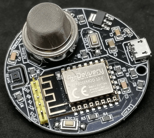
Auf dem AZ-Envy ist ein ESP8266 verbaut und zwei Sensoren. Der SHT30 Sensor dient für die Erfassung von Luftfeuchtigkeit und Temperatur sowie ein MQ-2 für Luftqualität.
Benötigte Ressourcen
Wenn du dieses Board wie nachfolgend programmieren und die Sensordaten vom AZ-Envy auslesen möchtest, dann benötigst du: - einen AZ-Envy, - ein Micro-USB Datenkabel, - ein FTDI232 Adapter, - ein Mini-USB Datenkabel, - drei Breadboardkabel, weiblich-weiblich, 10 cm
Anschluss des FTDI232 Adapters an den AZ-Envy
Der FTDI232 Adapter wird mit drei Breadboardkabel mit dem AZ-Envy verbunden. AZ-EnvyFTDI232 AdapterRXRXTXTXGNDGND Zusätzlich musst du das Board mit einem Micro-USB-Kabel verbinden, damit dieser Strom erhält.
Board AZ-Envy mit FTDI232 Adapter
Probleme mit dem Sensor MQ-2 & SHT30
Der Luftqualitätssensor MQ-2 wird im Betrieb sehr warm und durch die ungünstige Platzierung zur Nähe des Sensors SHT30 erhältst du von letzterem ggf. sehr ungenaue Werte.

Temperatur des MQ-2 Sensors im Betrieb In einigen Foren wurde bereits darüber sehr ausgiebig diskutiert. Eine Lösung dazu ist den Sensor SHT30 abzuschirmen, in der Platine ist eine kleine Rinne eingelassen, in welche man ein Schild einlassen kann und somit zumindest etwas Wärme vom Sensor ableiten kann.
Programmieren in der Arduino IDE
Wie du den Mikrocontroller in der Arduino IDE einrichtest, habe ich dir bereits im oben verlinkten Beitrag gezeigt. Im nachfolgenden YouTube-Video zeige ich dir, wie du am AZ-Envy die Sensordaten auslesen kannst. https://youtu.be/E8-UMpHXCOw Bibliotheken für die verbauten Sensoren Für das Auslesen der Sensoren benötigen wir zwei Bibliotheken, diese können wir über die Shopseite von AZ-Delivery zum Board als ZIP-Datei herunterladen und über Sketch > Include Library > Add .ZIP Library in der Arduino IDE importieren. Auslesen der Luftfeuchtigkeit und Temperatur vom SHT30 Sensor Der Sensor SHT30 liefert wie erwähnt die Temperatur sowie die relative Luftfeuchtigkeit. Nachfolgend nun ein kleines Programm, welches diese Daten ausließt und auf der seriellen Schnittstelle ausgibt. //Bibliothek zum auslesen der Sensorwerte //vom SHT30 Sensor #include //instanziieren eines Objektes vom Typ SHT3X //mit der I2C Adresse 0x44 SHT3X sht30(0x44); void setup() { //beginn der seriellen Kommunikation mit 9600 baud Serial.begin(9600); } void loop() { //Wenn die kommunikation per I2C mit dem Sensor //erfolgreich war, dann... if (sht30.get() == 0) { //lesen der Temperatur in Grad Celsius float temperature = sht30.cTemp; //lesen der rel. Luftfeuchtigkeit in % float humidity = sht30.humidity; //ausgeben der Temperatur Serial.print("Temperatur: "); Serial.print(temperature); Serial.println("°C"); //ausgeben der rel. Luftfeuchtigkeit Serial.print("rel. Luftfeuchtigkeit: "); Serial.println(humidity); Serial.println("%"); } //eine kleine Pause von 5 Sekunden delay(5000); }

Auslesen der Luftqualität des MQ-2 Sensors Der Luftqualitätssensor MQ-2 wird im Betrieb warm und liefert je länger die Läuft genauere Messwerte, daher würde ich dir empfehlen diesen für min. 1h laufen zu lassen, bevor du die echten Werte verwenden kannst. //Luftqualitätssensor MQ-2 ist //am analogen Pin A0 angeschlossen #define MQ2Pin A0 void setup() { //beginn der seriellen Kommunikation mit 9600 baud Serial.begin(9600); //analogen Pin als Ausgang definieren pinMode(MQ2Pin, INPUT); } void loop() { //lesen des analogen Wertes int sensorValue = analogRead(MQ2Pin); //Ausgeben des gelesenen Wertes auf //der seriellen Schnittstelle Serial.print("Luftqualität: "); Serial.print(sensorValue); Serial.println("ppm"); //eine kleine Pause von 2 Sekunden delay(2000); }

Wert im seriellen Plotter der Arduino IDE visualisieren
Die Arduino IDE verfügt über einen seriellen Plotter, welchen wir nutzen können, um Sensorwerte in einem Liniendiagramm zu visualisieren.

Dazu müssen wir die Legende und die Werte in einem bestimmten Format auf der seriellen Schnittstelle ausgeben. #include SHT3X sht30(0x44); #define MQ2Pin A0 float temperature = 0; float humidity = 0; void setup() { Serial.begin(9600); pinMode(MQ2Pin, INPUT); } void loop() { if (sht30.get() == 0) { temperature = sht30.cTemp; humidity = sht30.humidity; } int sensorValue = analogRead(MQ2Pin); Serial.print("Temperatur(°C):"); Serial.print(String(temperature, 2)); Serial.print("t"); Serial.print("rel.Luftfeuchtigkeit(%):"); Serial.print(String(humidity, 2)); Serial.print("t"); Serial.print("Luftqualität(analog):"); Serial.print(String(sensorValue, DEC)); Serial.println(); delay(2000); }
Download der Programme
Hier nun die gezeigten Programme zum einfachen Download als ZIP-Datei für die Arduino IDE. AZ-Envy - auslesen der Sensordaten - SHT30Herunterladen AZ-Envy - auslesen des Luftqualitätssensors - MQ-2Herunterladen AZ-Envy - visualisieren der Sensordaten im seriellen Plotter der Arduino IDEHerunterladen Read the full article
0 notes
Text
What Is a Circuit?? How Does a Circuit Works?? What are the Coding Languages For Circuits and How to code??

What Are Circuits?? : Circuits are pathways through which electrical current flows, allowing electronic devices to function.
How To connect these components in a basic circuit?? :
1. Complete the Circuit: Ensure there's a continuous path for the current to flow from the power source through the load and back to the source. Use wires to connect all the components in the loop.
2. Secure Connections: Make sure all connections are secure, using components like breadboards or soldering depending on the type of circuit.
How To Build A Complex Circuit:-
1. Select a Microcontroller: Choose a microcontroller or development board suitable for your project. Popular choices include Arduino, Raspberry Pi, ESP8266, ESP32, or custom-designed PCBs with microcontrollers like PIC, AVR, or STM32.
3. Choose a Coding Language: The choice of coding language depends on the microcontroller or platform you're using. Common languages include:
Arduino: C/C++ (Arduino IDE)R
aspberry Pi: PythonE
SP8266/ESP32: Arduino IDE (C/C++) or MicroPython
View all other points by clicking here 👇
Visit The Website 👇
0 notes