#ESP8266
Explore tagged Tumblr posts
Visit Tumblr Blog
Explore Tumblr blogs with no restrictions, modern design and the best experience.
Last Seen Tumblr Blogs


Fun Fact
The “We are the 99%” Tumblr blog became the slogan for the Occupy Wall Street movement.
Text
Espressif programmer test success! 💻✨🔧
While developing boards, there are oftentimes we want to program ESP chips without going through the onboard USB port; this adapter will help us (and others) do that! It has a CP2102N USB-serial chip
https://www.digikey.com/short/bm7n3p5z
...with RX/TX signal LEDs and two transistors wired up to the DTR/RTS line for the 'esptool standard' reset procedure technique. The output IO, plus a 3.3V 500mA regulated output, is available on a socket header, so you can plug wires in for quick programming and debugging. You can use this for everything from an ESP8266 up to the ESP32-P4! Here, we are testing it with a HUZZAH ESP8266 breakout board
...one of our first Espressif chipset products.
#espressif#esp8266#esp32#programmingtools#embeddeddevelopment#usbserial#cp2102n#diyhardware#electronicsengineering#hardwarehacks#embeddedprogramming#iotdevices#espchip#circuitdesign#prototypingtools#techinnovation#makersmovement#hardwaredevelopment#esp32p4#debuggingtools#huzzah#esp8266projects#techgadgets#microcontrollers#hardwaredebugging#esp32projects#diyelectronics#opensourcehardware#iotprojects#techtools
20 notes
·
View notes
Text
Chikken Chekkinator
I've been working on a thing for the past few weeks to keep track of chicken chores so we dont have to ask "have you fed the chickens" all the time

Its not finished, i need to get the final art printed but i'm pretty happy with it so far. It lights up different colours depending on who did the task, it gets saved to home assistant so you can view the status remotely and get reminders, and it changes its brightness based on the time of day so its not too bright at night.
i learned so much about microprocessor programming doing this and had a lot of fun. I think i want to make more things like this for helping my ADHD brain do regular tasks
here's the (almost) final artwork that i need to print for it:

i might do a technical writeup of how it works if people are interested
#microelectronics#diy project#esp8266#oc#going to post about some projects im working on because a shitpost i made broke containment and im gonna use that as motivation
8 notes
·
View notes
Text
DIY: Easiest Standalone Deauther

Previously, I have built a standalone Deauther with an OLED display and buttons over here, but realistically, everyone is just going to use the web interface. So, I recently found an ESP8266 ESP-07 USB module that is perfect for a standalone Deauther, since it has a USB connector built-in and you can just plug it into any powerbank. This module cost me around USD3 and you can find it in AliExpress.


First, we need to download the Deauther firmware. Go to this page and download this file: esp8266_deauther_2.6.1_DSTIKE_NODEMCU_07_V2.bin
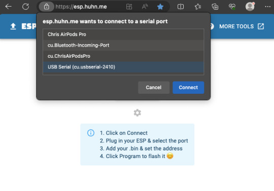
Next, set the switch on the ESP module to "PROG" and plug it into your computer's USB. Run Google Chrome or Microsoft Edge browser and go to https://esp.huhn.me. Click CONNECT and select the USB Serial item and click Connect.

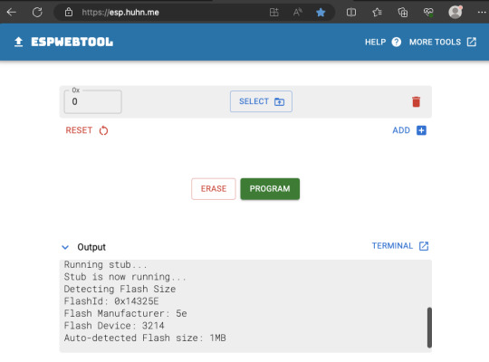
Now that it has successfully connected, click SELECT and choose the firmware file you downloaded earlier, then hit the PROGRAM button.

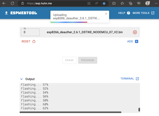
It should now start flashing, so just let it finish the job.
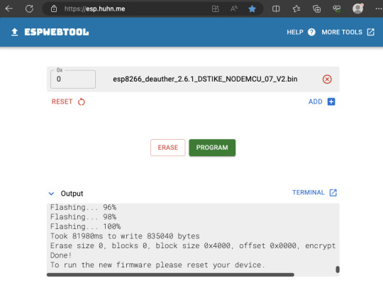
Finally, flick the switch on the ESP module from PROG to UART, and hit the reset button on the ESP module while still plugged into USB, or you can just remove it from your computer and plug it into a powerbank. On your phone/computer, just connect to the Wifi network "pwned" and use "deauther" for the password. Then open your web browser and go to http://192.168.4.1


That's it! You now have a standalone Deauther. More information about using the web interface over here. Also, realize that in most countries, there are laws against disrupting communication networks and Deauth attacks may be illegal.
4 notes
·
View notes
Text
2 notes
·
View notes
Text
DIY Gate Sensor for Home Assistant
#Adafruit Feather#automation#binary sensor#DIY#door#electronics#ESP8266#gate#GPIO#Home Assistant#make#making#microcontroller#notification#sensor#smart home
0 notes
Text
youtube
ESP8266
Visual Studio, CPP
Modul szeparáció, pointer, refernce (*, &)
0 notes
Text
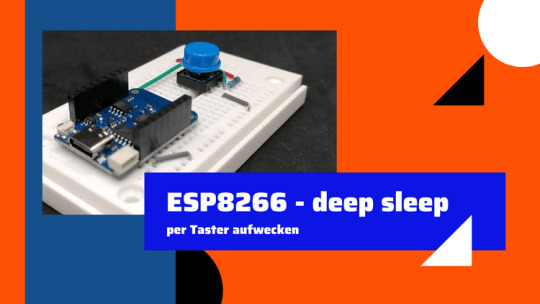
ESP8266 aus dem Deep Sleep mit einem Taster wecken

Wie du einen ESP8266 aus dem Deep Sleep mithilfe von einem Taster erwecken kannst, erfährst du in diesem Beitrag.
Ich habe dir bereits im Beitrag NodeMCU – Deep Sleep des ESP8266 gezeigt, wie du einen ESP8266 in den Deep Sleep versetzt und nach einer Zeit x dieser wieder selbständig erwacht und einen Text auf der seriellen Schnittstelle ausgibt.
Wozu der deep sleep?
Der deep sleep am Mikrocontroller lohnt sich, wenn du dein Projekt an einer Batterie betreiben möchtest. Aber auch wenn du Messwerte nur alle X Minuten, Stunden etc. benötigst, dann kann der deep sleep dir nützlich sein. Wenn ein Mikrocontroller in den deep sleep versetzt wird, dann spart dieser Strom und auch wird dieser nicht unnötig betrieben, somit lebt der Baustein deutlich länger.
Benötigte Ressourcen
Für den Nachbau dieses Beitrages benötigst du: - einen Microcontroller mit ESP8266 Chip*, - USB Datenkabel - einen Taster für die Printmontage*, - einen 10 kOhm Widerstand*, - ein 400 Pin Breadboard*, - diverse Breadboardkabel* Hinweis von mir: Die mit einem Sternchen (*) markierten Links sind Affiliate-Links. Wenn du über diese Links einkaufst, erhalte ich eine kleine Provision, die dazu beiträgt, diesen Blog zu unterstützen. Der Preis für dich bleibt dabei unverändert. Vielen Dank für deine Unterstützung!
Aufbau der Schaltung
In diesem Beitrag verwende ich den Wemos D1 Mini V4 mit USB-Schnittstelle. Dieser Mikrocontroller verfügt über den "normalen" ESP8266 Chip jedoch über eine USB-Typ-C Schnittstelle. Der Taster in dieser Schaltung wird mit dem Pin RST des Mikrocontrollers verbunden sowie per 10 kOhm PULL Up Widerstand mit 3.3V VCC. Der andere Pin des Tasters wird mit GND verbunden.

Schaltung - ESP8266, mit Taster
Programmieren - ESP8266 per Taster aus dem deep sleep erwecken
Der nachfolgende Code dient dazu, den Mikrocontroller per Tastendruck aus dem deep sleep zu erwecken. Die Codezeile in der Funktion loop wird nie erreicht, da der Mikrocontroller bereits in der Funktion setup wieder in den Tiefschlaf versetzt wird. void setup() { //beginn der seriellen Kommunikation mit 9600 baud Serial.begin(9600); //setzt den Timeout auf 2000 Millisekunden Serial.setTimeout(2000); //Warten darauf das die serielle Kommunikation aufgebaut wurde while (!Serial) {} //Ausgeben der Textzeilen auf der seriellen Schnittstelle Serial.println("Juhu, hier bin ich wieder!"); //zusätzlich noch einmal die Millisekunden seit dem Start Serial.print("läuft seit "); Serial.println(millis()); //den Mikrocontroller in den deep sleep versetzen ESP.deepSleep(0); } void loop() { //diese Zeile wird nie erreicht! Serial.println("Hallo!"); } Read the full article
0 notes
Text

Transform Your Space with These DIY ESP8266 Smart Projects: https://findingdiy.com/diy-projects/?search=esp8266+projects
#diy projects#findingdiy.com#findingdiy#diy#diy projects search engine#diy project#do it yourself#diy activities#Wednesday#wednesday motivation#esp8266
0 notes
Text
Understanding ESP32 Pin Configuration: A Developer's Guide
The ESP32 microcontroller has become a cornerstone of IoT development, thanks to its versatility and powerful features. One of the most crucial aspects of working with ESP32 is understanding its pin configuration and capabilities. Let's dive into the essential aspects of ESP32 pins that every developer should know.

GPIO Pins Overview
The ESP32 boasts up to 34 GPIO (General Purpose Input/Output) pins, but not all are available for use in most development boards. Some key points about ESP32 pins:
GPIO 6-11: Reserved for internal SPI flash connection
GPIO 34-39: Input-only pins with no internal pull-up/pull-down resistors
ADC Capabilities: Two 12-bit SAR ADCs, supporting 18 measurement channels
Touch Sensors: Up to 10 capacitive touch GPIOs
Special Function Pins
Several pins serve dual purposes or have specific functions:
Boot Mode Pins GPIO 0: Bootloader mode when pulled low during reset GPIO 2: Connected to on-board LED in many development boards
UART Pins GPIO 1 (TX) and GPIO 3 (RX): Default UART0 communication Often used for flashing and debugging
SPI Pins VSPI: GPIO 5 (CS), 18 (CLK), 19 (MISO), 23 (MOSI) HSPI: GPIO 14 (CLK), 12 (MISO), 13 (MOSI), 15 (CS)
Best Practices for Pin Usage
Strapping Pins Always check the strapping pin status before using GPIO 0, 2, 4, 5, 12, and 15. These pins may affect boot behavior if incorrectly configured.
Input-Only Pins When designing sensor interfaces, prefer GPIO 34-39 for analog inputs as they're input-only and less susceptible to noise.
Pull-up/Pull-down Configuration
ADC Usage ADC1: Can be used with Wi-Fi/Bluetooth active ADC2: Only available when Wi-Fi/Bluetooth is disabled
Common Pitfalls to Avoid
Don't use GPIO 6-11 in your projects as they're connected to the internal SPI flash.
Avoid using strapping pins for critical functions that can't be changed during boot.
Remember that GPIO 34-39 don't have internal pull-up/pull-down resistors.
Be cautious with voltage levels - ESP32 pins operate at 3.3V.
Conclusion
Understanding ESP32 pinout is fundamental for successful project development. By following these guidelines and best practices, you can avoid common issues and make the most of your ESP32's capabilities. Remember to always consult the official ESP32 technical reference manual for detailed specifications and updates.
#ESP32 #PinConfiguration #DevelopersGuide #Microcontrollers #EmbeddedSystems #IoT #Programming #Hardware #Electronics #Arduino #ESP32S2 #ESP32C3 #ESP32C2 #ESP32C6 #ESP32S3 #ESP32H2 #ESP32P1
#ESP32#microcontroller#pinconfiguration#GPIO#ADC#DAC#I2C#SPI#UART#PWM#analog#digital#input#output#microcontrollers#embeddedsystems#IoT#InternetOfThings#electronics#hardware#software#programming#development#Arduino#ESP8266#RaspberryPi#microcontrollerprogramming#embeddedprogramming#IoTdevelopment#electronicdesign
1 note
·
View note
Video
youtube
Automatic Rent Reminder using esp8266
0 notes
Text

A little Espressif helper for programming
While developing boards, we often want to program ESP chips without going through the onboard USB port; this adapter will help us (and others) do that! It has a CP2102N USB-serial chip
https://www.digikey.com/short/bm7n3p5z
with RX/TX signal LEDs and two transistors wired up to the DTR/RTS line for the 'esptool standard' reset procedure technique. The output IO, plus a 3.3V 500mA regulated output, is available on a socket header, so you can plug wires in for quick programming and debugging. You can use this for everything from an ESP8266 to an ESP32-P4!
#espressif#esp8266#esp32#programmingtools#hardwaredev#cp2102n#usbtoserial#iotdevelopment#debuggingtools#esptool#opensourcehardware#devboards#electronicsproject#makerlife#techinnovation#embeddedengineering#hardwarehack#electronicsdesign#developerlife#codinghardware#prototyping#electronicsengineering#hardwarehacking#chipprogramming#serialadapter#diyelectronics#esp32projects#debugging#iotdevices#electronicsenthusiast
17 notes
·
View notes
Text
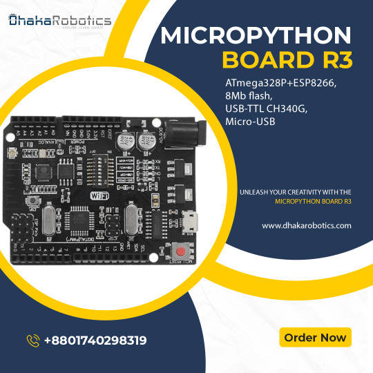
Introducing the MicroPython Board R3 ATmega328P+ESP8266!
Are you ready to take your projects to the next level? Meet the MicroPython Board R3, a powerhouse combining the classic ATmega328P microcontroller with the versatile ESP8266 WiFi chip. Here’s why you’ll love it:
Dual Processors: Enjoy the best of both worlds with the ATmega328P and ESP8266 working together or independently.
8MB Flash Memory: Store more with 8MB of flash memory, perfect for complex projects and data-heavy applications.
USB-TTL CH340G: Seamless USB connectivity with the CH340G converter, making programming and debugging a breeze.
Micro-USB Port: Convenient and modern Micro-USB port for easy power and data transfer.
Versatile Applications: Ideal for IoT projects, home automation, robotics, and more. The possibilities are endless!
Whether you’re a hobbyist or a professional, the MicroPython Board R3 is designed to meet your needs. Get yours today and start creating!
Order Now: https://dhakarobotics.com/.../1039-micropython-board-r3.../
Contact Us: +8801740298319
visit our website: https://dhakarobotics.com/
0 notes
Text
DIY: Adding External Antenna to D1 Mini

I have been using a D1 Mini for Deauther on Flipper Zero, but the range with the build-in antenna was rather mediocre, so it’s time to do some modding.
Rather than soldering the antenna cable directly to the D1 Mini, I decided to solder an IPEX connector to the D1 Mini instead. This way, I can easily change different length cables as needed.


First, we need to use a blade to make cuts to the existing build-in antenna to disconnect it, as shown in the photos below. Use a multimeter to check that the connection is really severed.


Here’s how the IPEX connector should be positioned. The center pin of the connector is the signal. Apply some soldering paste to make it easier to solder and after soldering, use a multimeter to double check that everything is properly connected and nothing is shorted.
Also, just put a tiny dab of superglue to the edge of the IPEX connector that was not soldered on. This will ensure that we don’t rip out the connector when we disconnect the antenna cable.


That’s it, we’re done. It’s a fairly simply mod. Now to try it out.

From my quick tests with a 3dbi external antenna, Deauther was able to find about 3-4 times more access points. Awesome!
If you enjoy stuff like this, check out our Makers & Hackers Exchange Facebook group
2 notes
·
View notes
Video
youtube
Ejemplo de webserver para wemos d1 esp8266 en arduino
#youtube#ejemplo#ejemplos#arduino#wemos d1#web server#web server en arduino#programas arduino#ejemplos arduino#esp8266
1 note
·
View note
Text
DIY Air Quality Monitors for Home Assistant
#air quality#capacitor#DIY#electronics#ENS160#ESP8266#ESPHome#Home Assistant#humidity#JST connector#make#making#particulate matter#SEN50#Si7120#soldering#temperature#VOC#Wemos D1
0 notes
Text
Ouija 8266
In 2021, I created this ESP8266 programmer that looks like a Ouija board planchette. You can attach an ESP-01 module, plug in an FTDI cable, and program the module from your computer using the Arduino IDE – then wear the programmer as an earring!

Here's the full write-up:
1 note
·
View note