#flash EEPROM
Explore tagged Tumblr posts
Visit Tumblr Blog
Explore Tumblr blogs with no restrictions, modern design and the best experience.
Last Seen Tumblr Blogs


Fun Fact
Tumblr has a 66 index score for customer satisfaction in the US.
Text
https://www.futureelectronics.com/p/semiconductors--memory--RAM--eeprom--i2c-interface-protocol/cat24c64wi-gt3-onsemi-8463176
Random Access Memory, what is an EEPROM, programmable EEPROM manufacturers, ROM
CAT24C64 Series 64 Kb (8K X 8) 1.8 - 5.5 V I2C CMOS Serial EEPROM - SOIC-8
#RAM#EEPROM#I2C Interface Protocol#CAT24C64WI-GT3#onsemi#Random Access Memory#programmable EEPROM manufacturers#ROM#EEPROM microchip programming#EEPROM memory chip#flash EEPROM#electrically erasable programmable read only memory
1 note
·
View note
Text
youtube
Page EEPROM vs Serial Flash Technologies with STMicroelectronics
https://www.futureelectronics.com/resources/featured-products/stmicroelectronics-serial-eeprom . See the unique advantage, features and applications of Page EEPROM vs Serial Flash technologies in this STMicroelectronics video. https://youtu.be/gTxIi8oTH30
#Page EEPROM#Page EEPROM vs Serial Flash#Serial Flash#Serial Flash Technologies#STMicroelectronics#EEPROM#EEPROM vs Serial Flash#future#electronics#future electronics#Youtube
0 notes
Text
CG FC200 Full Backup 2020 Peugeot Partner MD1CS003 EEPROM and Flash on Bench
CG FC200 ECU Programmer Performs Full Backup of 2020 Peugeot Partner MD1CS003 EEPROM and Flash on Bench
CG FC200 ECU Programmer successfully performed a full backup of the 2020 Peugeot Partner MD1CS003 ECU’s EEPROM and Flash data, without the need to open or physically access the unit. This particular ECU model is the BOSCH MD1CS003 TC298TP.

Equipment Used:
CG FC200 ECU Programmer, fully equipped with all licenses activated.
Operation Process:
1. Began by viewing the wiring diagram in the FC200 software.

2. Following the diagram, we established the connection between the FC200 programmer and the ECU using the professional car-grade wiring harness provided in the FC200 kit.
3. Next, we connected the FC200 to a laptop using a USB cable and ensured that the programmer was powered.


4. Launched the FC200 software and selected the corresponding ECU model to access the operation interface.

5. By clicking the “Identify” function, the FC200 intelligently identified the ECU communication and wiring connections while simultaneously reading out the ECU information.

6. Then, with a simple click on “Read EEPROM” and “Read Flash,” we sequentially read and backed up the necessary data.
7. The entire process was completed smoothly and efficiently within just 4 minutes.


Our client expressed complete satisfaction with the ease and speed of the operation. With CG FC200 ECU Programmer, we were able to accomplish the task flawlessly, providing a successful full backup of the 2020 Peugeot Partner MD1CS003 ECU’s EEPROM and Flash data on the bench.
0 notes
Text
CG FC200 Full Backup 2020 Peugeot Partner MD1CS003 EEPROM and Flash on Bench
CG FC200 ECU Programmer Performs Full Backup of 2020 Peugeot Partner MD1CS003 EEPROM and Flash on Bench
CG FC200 ECU Programmer successfully performed a full backup of the 2020 Peugeot Partner MD1CS003 ECU’s EEPROM and Flash data, without the need to open or physically access the unit. This particular ECU model is the BOSCH MD1CS003 TC298TP.

Equipment Used:
CG FC200 ECU Programmer, fully equipped with all licenses activated.
Operation Process:

Began by viewing the wiring diagram in the FC200 software.
Following the diagram, we established the connection between the FC200 programmer and the ECU using the professional car-grade wiring harness provided in the FC200 kit.
Next, we connected the FC200 to a laptop using a USB cable and ensured that the programmer was powered.
Launched the FC200 software and selected the corresponding ECU model to access the operation interface.
By clicking the “Identify” function, the FC200 intelligently identified the ECU communication and wiring connections while simultaneously reading out the ECU information.
Then, with a simple click on “Read EEPROM” and “Read Flash,” we sequentially read and backed up the necessary data.
The entire process was completed smoothly and efficiently within just 4 minutes.


Our client expressed complete satisfaction with the ease and speed of the operation. With CG FC200 ECU Programmer, we were able to accomplish the task flawlessly, providing a successful full backup of the 2020 Peugeot Partner MD1CS003 ECU’s EEPROM and Flash data on the bench.
0 notes
Text
VVDI2 Volvo XC90 2004 AKL Transponder problem
I own a 2004 Volvo XC90 AKl. I used SMOK JTAG to read the 28F400 flash from the CEM in BDM. Then, I used Xhorse vvdi2 to create a new chip, ID 48, and successfully wrote the file back. Put everything back but no crank. The only fault code present in the CEM is related to the transponder. It seems like VVDI2 did not perform well in this case, has anyone else managed to successfully work on this particular car using VVDI2?

Here is the solution:
You can do them all by reading eeprom, then writing it to a super chip. Don’t write anything back, all of them worked.
Customer feedback:
I've sorted it. JTAG for some reason swaps the bytes and before you use that file you need to swap the bytes. Then I did a super chip with Xhorse vvdi2 and started the car. Without writing anything back, thanks for your help.
0 notes
Text
Didnt get much done today still kicking it into gear, I did flash the T-Deck with Meshtastic firmware which worked flawlessly and I was going to set up the Halow board but I need to get or rig up an eeprom programmer for that so that'll have to wait until I have time to hash that out
12 notes
·
View notes
Text
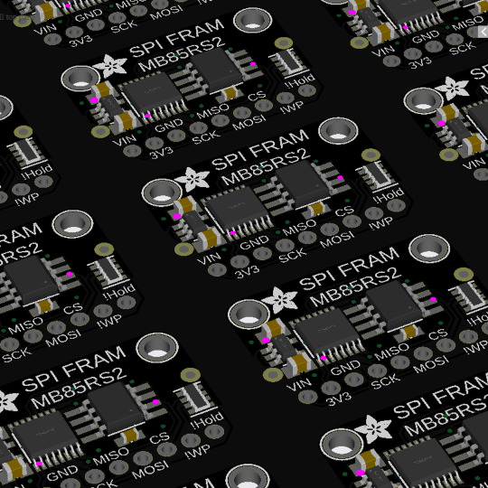
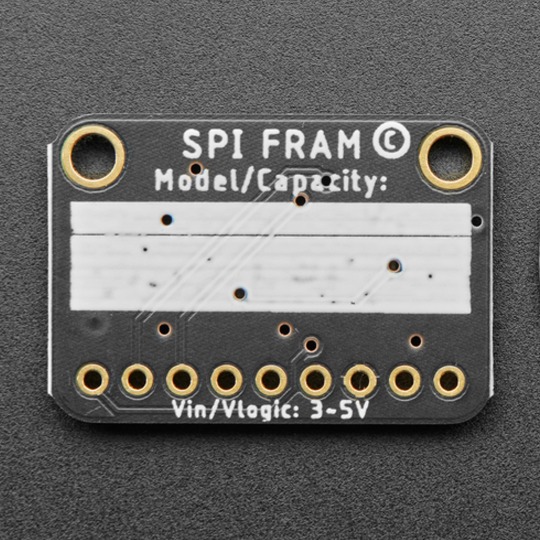
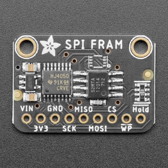
PCB of the Day! SPI Non-Volatile FRAM Breakout - 2 Mbit / 256 KBytes - MB85RS2MTA 🔌🛠️💾
Similar to Dynamic random-access memory, only with a ferroelectric layer instead of a dielectric layer. This gives it stable handling (the bytes you write are non-volatile) with dynamic responsiveness (you can write them very fast!). With our SPI FRAM breakout board, you can add FRAM storage to your next DIY project. FRAM allows for lower power usage and a faster write performance. It's excellent for low-power or inconsistent-power data logging or data buffering, where you want to stream data fast while keeping the data when there's no power. Unlike Flash or EEPROM, there are no pages to worry about. Each byte can be read/written 10,000,000,000,000 times, so you don't have to worry too much about wear leveling.
#adafruit#electronics#opensource#opensourcehardware#pcboftheday#pcb#spi#fram#memory#ram#flash#diyproject#datastorage#lowpower#fastwrite#datalogging#databuffering#nonvolatile#wearleveling#techinnovation#electronicsdiy
3 notes
·
View notes
Text
EEP ROM is some masterful typography. It's cute and technically accurate!
See at first we had mask ROMs: this is where you have a chip that's designed from the start to only have some specific data on it. That's why it's Read Only Memory: it's memory, but you can only read it. This is what, like, NES games were built on: the game is on the ROM chip, and can't be changed.
Then someone figured out you could make the chip so that it starts out blank, then you can program it once (like burning a CD-R), so we called these Programmable ROMs: PROMs.
And then another clever engineer worked out how to make them re-erasable, by using ultraviolet light that causes the bits to weaken. You have to take out the chip, expose it in a special box (you can't just have a flashlight, because UV light will give you skin cancer and sunburns on your eyes), then program it and put it back in. But hey, it's erasable and reusable now! This is how a lot of games were developed for cartridge consoles: you'd have a special cartridge that has exposed chips, which you program and put back in the console to test. This new erasable and programmable ROM was obviously called the Erasable Programmable ROM, or an EPROM.
But then a very clever trick was figured out: if you use quantum mechanical effects you can trap charge in a tiny cell and get it out using quantum tunneling, which means you can erase it in-situ! Now you have a reusable (for a while) rewritable chip, so it was called Electrically Erasable Programmable Read Only Memory: EEPROM!
But by putting a space in it, they made it an EEP ROM, which is a much cuter name.
BTW EEPROMs are what flash memory grew out of: this is a 1985 SD card.

955 notes
·
View notes
Text
Hi-Tech Khanna: India’s Expert in Immobilizer & ECM Training
Hi-Tech Khanna is India’s leading training institute for Immobilizer and Car ECM (Electronic Control Module) repair, offering specialized programs for automotive technicians, locksmiths, and electronics professionals. With increasing use of security systems in modern vehicles, immobilizer and key programming knowledge has become essential for anyone in the automotive diagnostics and repair field.
Located in Punjab and recognized across India—from Delhi and Gujarat to Mumbai and Hyderabad—Hi-Tech Khanna delivers hands-on, job-ready training in immobilizer system diagnostics, transponder key repair, and ECM communication protocols. Their courses cover the working principles of immobilizers, key matching, reprogramming, and fault troubleshooting using the latest diagnostic tools.
The Immobilizer Repair Training Program is designed for those aiming to master anti-theft system repair, transponder chip replacement, EEPROM reading, and synchronization between the key, ECM, and immobilizer box. Trainees work on real modules from popular vehicle brands, learning to solve real-world problems confidently.
In parallel, the Car ECM Training Course offers deep insights into ECU architecture, fault codes, circuit repair, software flashing, and BS6-compliant systems—empowering students to become well-rounded automotive electronics experts.
With a strong national presence and alumni working across India, Hi-Tech Khanna is known for its practical approach, skilled trainers, and post-training support. They also offer online classes, making it easy for students across the country to learn remotely with live demonstrations and expert guidance.
If you're looking for the best institute for immobilizer repair training and car ECM programming in India, Hi-Tech Khanna stands out for quality, affordability, and results.
#HiTechKhanna#ImmobilizerRepairIndia#ECMTrainingIndia#KeyProgrammingCourse#AutomobileElectronics#ImmobilizerTrainingInstitute#TransponderKeyRepair#CarECMRepair#AutomotiveSecurityTraining#EEPROMProgramming#BS6TrainingIndia#ECURepairCourse#IndiaAutoTraining
0 notes
Text
A Comprehensive Guide to Firmware Development

In the world of embedded systems and smart devices, firmware plays a critical role in enabling hardware to function effectively. Whether you're developing IoT devices, automotive systems, or industrial machinery, firmware development is the backbone that bridges hardware and software.
In this blog post, we’ll explore what firmware is, its importance, the development process, tools used, and best practices to ensure efficient and secure firmware solutions.
What is Firmware?
Firmware is a specialized type of software that provides low-level control for a device's specific hardware. Unlike regular software applications, firmware is tightly coupled with the hardware and is often stored in non-volatile memory such as ROM, EEPROM, or flash memory.
Examples of devices with firmware include:
Smartphones
Routers
Smart TVs
Medical devices
Automotive control units (ECUs)
Why is Firmware Important?
Firmware is essential because it:
Controls hardware operations: Without firmware, the hardware components of a device would be non-functional.
Ensures device functionality: It manages startup routines, I/O operations, sensor integration, and communication protocols.
Supports software-hardware integration: Firmware acts as a middle layer, allowing high-level software applications to interact with low-level hardware components.
Enables updates: Firmware can often be updated to fix bugs, enhance performance, or add features.
The Firmware Development Process
1. Requirements Gathering
Understanding the hardware specifications and the device’s purpose is crucial. Developers need to gather requirements from both hardware engineers and end users.
2. Architecture Design
This involves deciding on the architecture and communication protocols (e.g., I2C, SPI, UART), memory usage, and timing constraints.
3. Choosing a Development Platform
Most firmware is written in C or C++ due to their efficiency and hardware-level access. You’ll also need:
Microcontroller/microprocessor datasheets
Board Support Packages (BSPs)
RTOS (Real-Time Operating System), if required
4. Coding and Integration
Firmware code is written to interface directly with hardware. This includes writing drivers for peripherals (LEDs, sensors, motors) and managing power consumption, timing, and interrupts.
5. Testing and Debugging
Testing includes:
Unit testing
Hardware-in-the-loop (HIL) testing
Simulation and emulation tools
Debugging tools such as JTAG and SWD are used to step through code and analyze performance.
6. Deployment
Once tested, firmware is compiled and flashed onto the device using programmers or over-the-air (OTA) update mechanisms.
Tools Used in Firmware Development
Integrated Development Environments (IDEs): Keil µVision, MPLAB X, STM32CubeIDE
Compilers and Toolchains: GCC, IAR Embedded Workbench
Debuggers/Programmers: JTAG, ST-LINK, AVR ISP
Version Control Systems: Git
Simulators/Emulators: QEMU, Proteus
Best Practices for Firmware Development
Write modular and reusable code
Follow coding standards (e.g., MISRA C for safety-critical systems)
Optimize for memory and power consumption
Document thoroughly for maintainability
Implement fail-safes and watchdog timers
Secure your firmware (e.g., with encryption and secure boot loaders)
Plan for firmware updates with mechanisms like OTA updates
0 notes
Text
What Is Firmware Development?

In today’s increasingly connected world, embedded systems power everything from smart home devices to medical equipment and automotive technology. At the heart of these systems lies firmware development—a specialized field that ensures devices run smoothly, efficiently, and securely. If you're building any smart or electronic product, understanding firmware and investing in expert firmware development is key to delivering performance, reliability, and innovation.
What Is Firmware?
Firmware is a type of software that provides low-level control over a device's hardware. Unlike traditional software applications, firmware resides in the device’s memory (often in ROM, flash, or EEPROM) and interfaces directly with the hardware components.
Firmware is what tells a device how to operate, boot, and respond to external commands. It’s typically involved in controlling:
Microcontrollers (MCUs)
Sensors
Actuators
Display modules
Communication modules (e.g., Wi-Fi, Bluetooth)
Because of its vital role, firmware development is an essential part of the embedded systems lifecycle.
What Is Firmware Development?
Firmware development is the process of designing, programming, testing, and maintaining the firmware that controls electronic hardware. Developers work at the intersection of hardware and software, writing code that interacts directly with microprocessors and chipsets.
This type of development typically involves:
Selecting the right microcontroller or system-on-chip (SoC)
Programming in low-level languages like C, C++, or Assembly
Interfacing with hardware peripherals
Real-time operating system (RTOS) integration
Debugging and testing using tools like JTAG, oscilloscopes, or logic analyzers
Updating and maintaining firmware post-deployment
Well-executed firmware development ensures that devices are not only functional, but also stable, efficient, and secure.
Why Firmware Development Is Crucial
In a world driven by smart technology, firmware development plays a critical role in the success of a product. Here’s why:
1. Optimized Performance
Firmware directly controls hardware operations. Efficient firmware code leads to faster processing, lower power consumption, and improved user experience.
2. Hardware Integration
Firmware allows software and hardware to communicate seamlessly. Whether it’s a smart thermostat or a medical device, firmware development ensures that components such as sensors, motors, and displays function correctly.
3. Product Reliability
Poorly written firmware can result in device malfunctions, crashes, or safety issues. Reliable firmware ensures devices perform predictably under various conditions.
4. Security
Many cyberattacks target firmware vulnerabilities. Secure firmware development practices, including encryption and authentication, are essential to protect devices and user data.
5. Upgradability
Modern devices often require firmware updates to fix bugs or add features. Proper firmware development includes designing systems that support over-the-air (OTA) updates without bricking the device.
Industries That Rely on Firmware Development
The demand for skilled firmware development is booming across various sectors:
Consumer electronics (smartphones, smart TVs, wearables)
Automotive (ADAS, electric vehicles, infotainment systems)
Industrial automation (IoT sensors, PLCs, robotics)
Healthcare (wearable monitors, infusion pumps, diagnostic devices)
Telecommunications (network hardware, routers, modems)
Aerospace and defense (navigation systems, avionics)
Whether it’s a smartwatch or a life-saving medical device, firmware is often the unseen hero behind the scenes.
Best Practices in Firmware Development
To ensure a successful project, firmware developers follow a structured approach:
Clear hardware documentation: Understand the chipset’s datasheets and schematics before writing code.
Modular design: Create reusable and maintainable code blocks.
Version control: Use Git or SVN to track changes and collaborate efficiently.
Automated testing: Implement unit tests and simulation environments to catch bugs early.
Debugging tools: Use debuggers and analyzers to test real-world behavior.
Code optimization: Ensure the code is fast, power-efficient, and small in memory footprint.
Partnering with experienced firmware developers is essential to bring a hardware product to life without delays or technical setbacks.
The Future of Firmware Development
As more industries adopt IoT, artificial intelligence, and edge computing, firmware development is becoming even more critical. We’re seeing trends like:
AI-powered firmware for smart decision-making
Increased emphasis on security and firmware-level encryption
Remote firmware updates through cloud platforms
Low-power firmware for battery-dependent IoT devices
Staying on top of these trends can give your business a competitive advantage in delivering cutting-edge, reliable technology.
Conclusion
Firmware development is the backbone of modern electronics, enabling smart devices to operate safely, efficiently, and intelligently. From prototyping to production and post-launch updates, investing in expert firmware development is crucial for any business building connected hardware.
Whether you're launching a new product or improving an existing one, working with skilled firmware developers can save time, reduce costs, and ensure your technology stands out in a crowded market.
0 notes
Text
The future of smart home control begins with one sleek, powerful interface — the Nextion NX8048P050-011R 5.0” Intelligent Resistive HMI Touchscreen. Ideal for automation projects, this display offers unmatched user experience, intelligent processing, and seamless integration. If you're planning to level up your smart home or automation setup in 2025, this intelligent touchscreen should be on your radar.
Available now at www.sonoff.in, this module is a must-have for developers, hobbyists, and smart home enthusiasts.
Power-Packed 5.0” Intelligent Display for Smart Control
The Nextion NX8048P050-011R boasts a 5.0-inch resistive touchscreen, offering sharp visuals and precise touch response. Designed without an enclosure, this screen gives flexibility in mounting it into custom panels, enclosures, or control stations.
The resistive touch feature supports usage even when wearing gloves — making it practical for industrial, automation, and DIY applications. It’s a display that adapts to your environment, not the other way around.
Advanced HMI Capabilities Built for Efficiency
This is more than just a screen. It's a powerful HMI (Human Machine Interface) equipped with:
Onboard microcontroller for fast UI rendering
Rich GUI design with Nextion Editor
Easy drag-and-drop interface development
Support for static images, buttons, sliders, and dynamic text
Integrated flash memory for storing UI pages
You can build multi-layered smart interfaces without relying on external MCUs for rendering. Control everything from HVAC to lighting systems — with just a touch.
Streamlined Communication with Embedded Systems
The Nextion NX8048P050-011R communicates using UART serial communication, making it compatible with Arduino, Raspberry Pi, ESP32, and more. Developers love how it simplifies hardware-software interaction.
Commands are sent via a simple serial interface, which dramatically reduces processing load on your main MCU. This allows developers to allocate power where it truly matters.
Why It’s Perfect for Home and Industrial Automation
Here’s why the Nextion NX8048P050-011R is a game changer:
Compact but powerful – Fits in tight spaces while delivering advanced UI functionality.
Customizable UI – Create polished, user-friendly interfaces tailored to your smart home design.
Responsive Touch – Reliable performance in both residential and industrial settings.
Highly Compatible – Works seamlessly with Sonoff smart switches and automation modules from www.sonoff.in.
Whether you’re managing lighting, thermostats, or entire smart systems, this touchscreen gives you intuitive and elegant control.
Nextion Editor – No Code? No Problem.
The Nextion Editor software is a dream for non-programmers. You don’t need advanced coding skills to build dynamic user interfaces. Just drag and drop components onto your screen canvas.
From progress bars to image sliders, your interface can be as simple or complex as your imagination allows. With built-in event triggers, automation becomes a breeze.
Technical Specs at a Glance
Let’s dive into the core specs that make this touchscreen a powerhouse:
Display Size: 5.0” resistive touch panel
Resolution: 800x480 pixels
Flash Memory: 16MB
RAM: 3584 bytes
EEPROM: 1024 bytes
MCU: 48MHz
Serial Port: TTL UART
Operating Voltage: 5V
These specifications ensure smooth performance, fast response, and consistent reliability in demanding automation environments.
Installation and Custom Integration
Thanks to its open-frame design, you can install the NX8048P050-011R in custom enclosures or panels. Whether it’s a wall-mounted control panel or embedded into a furniture piece, the flexibility is unbeatable.
Pair it with Sonoff Wi-Fi switches or smart relays to create a smart home interface that looks and feels professional.
Smart Solutions, Smarter Shopping with www.sonoff.in
Looking for a reliable supplier in India? www.sonoff.in is the trusted destination for Nextion displays, Sonoff smart devices, and complete home automation solutions.
They offer fast delivery, excellent customer service, and authentic products backed by warranty. Get access to India’s top smart home gadgets — all in one place.
Conclusion: Smart Control Starts Here
The Nextion NX8048P050-011R 5.0” intelligent touchscreen is the perfect HMI solution for next-gen smart home setups. Its seamless performance, rich feature set, and compatibility with Sonoff devices from www.sonoff.in make it a standout choice.
Don't settle for clunky switches and outdated interfaces. Take control of your environment — the smart way.
Explore the future of home automation at www.sonoff.in and power up your smart living journey today.
#sonoff#smarthome#smartappliances#googlehomeintegration#alexacompatible#sonoffpowr3#homeautomation#sonoffindia#wifismartswitch
0 notes
Link
[ad_1] Non-volatile memory is an important component in a wide range of high-performance embedded applications. Especially, many consumer, industrial, and medical applications need increased re-writability to support both more frequent code updates as well as increased data logging. These applications require greater memory density to store either a substantially larger code footprint and/or more extensive data logs. Moreover, developers need to be able to improve power efficiency while lowering system cost. Today, there are numerous non-volatile memory technologies available to developers, including EEPROM, NOR flash, NAND flash, MRAM, and FRAM. Each has its own distinct advantages for specific applications. However, the combination of 1) manufacturing process technologies continuing to scale smaller, 2) the need for higher densities at lower power, and 3) re-writability becoming increasing important has led to increased interest in RRAM for these applications. This article will explore RRAM technology and how it provides developers with a new approach to meeting the changing memory requirements of high-performance embedded systems. Memory in high-performance embedded systems Emerging connected systems face a number of tough design challenges. For instance, medical devices—such as hearing aids, continuous glucose monitors (CGMs), and patches—must fit into a smaller form factor despite increasing data and event logging requirements necessary to enable remote monitoring and compliance with industry standards. Next, smart equipment in Industry 4.0 systems require significantly greater code storage to facilitate functionality like remote sensing, edge processing, and firmware over-the-air (FOTA) updates for remote maintenance. Furthermore, the addition of artificial intelligence (AI) at the edge in wearables and Internet of Things (IoT) devices is driving the need for high-performance, energy-efficient non-volatile memory in smaller form factors. The increased code size and data logging requirements of such systems exceeds the embedded non-volatile memory capabilities of microcontrollers. External memory is needed to match increasing density and performance requirements. However, code and data often need varying capabilities depending upon performance, density, endurance, and data-write size. Thus, multiple non-volatile memories may have to be used, such as NOR flash for data logging and high-density EEPROM for code storage. This can lead to systems that use several types of external memory, increasing system cost, complexity, and energy consumption. Ideally, systems can use a single memory type that supports both external code and data storage without compromising performance or functionality for either. An emerging non-volatile technology to fill this gap as a standalone external memory is RRAM. Resistive RAM Resistive RAM (RRAM) is a non-volatile random-access memory that was made available commercially in the early 2000s. It operates by changing the resistance of a switching material sandwiched between two electrodes, show on left in Figure 1. Figure 1 Typical RRAM memory cell consists of one transistor and one resistor (left), and the memory state is altered by applying an external bias across the metal electrodes (right). Source: Infineon The switching material can be metal oxide or a conductive bridging switching media. A typical RRAM memory cell consists of one transistor and one resistor pair (1T1R) where the resistance of the RRAM can be altered with an external bias applied across the metal electrodes, shown on the right side of Figure 1. Initially, RRAM was developed as a potential replacement for flash memory. At the time, the cost and performance benefits of RRAM weren’t enough to supersede the advantages of other non-volatile memory technologies, especially as an external memory. However, in recent years, several factors have changed to make RRAM a compelling non-volatile alternative. Specifically, as embedded systems become more integrated and implemented in smaller manufacturing process nodes with substantially larger code and data storage requirements, the following advantages of RRAM for external memory overtake traditional non-volatile options: Scalability Some non-volatile memory technologies are limited in their ability to scale, translating to limitations in overall memory density due to footprint, power, and cost. A major advantage of RRAM is that it can be manufactured in a compatible CMOS process, enabling it to scale to process nodes below 45 nm and even down as low as 10 nm. For example, the memory industry has had difficulty cost-effectively scaling NOR flash memory as the technology seems to be physically limited to between 35 and 40 nm. Scalability has a direct impact on performance, density, footprint, and energy efficiency. Direct write Data storage for a NOR flash memory requires two operations: an erase operation to clear the target address followed by a write operation. The “direct write” functionality of RRAM eliminates the need to first erase memory. Thus, only a write operation is required to store data. Figure 2 shows the operations required for writing to both NOR flash and RRAM. Figure 2 NOR flash requires an erase operation before every write operation, increasing write time, energy consumption, and wear on memory cells. RRAM’s ability to direct write speeds write operations, conserves energy, and extends cell endurance. Source: Infineon This leads to much faster large-scale write operations for RRAM, such as during FOTA updates. Byte re-writeable Some non-volatile memories perform writes based on page size. For example, NOR flash page size is typically either 256 or 512 bytes. This means every write impacts the entire page. To change one byte, the page must be read and stored in a temporary buffer; the change is made to the temporary duplicate. The flash must then erase the page and write the entire page back in from the buffer. This process is time-consuming and wears the flash (typically 100k+ writes). In addition, data cells that are not changed are worn unnecessarily. Consequently, data logging with NOR flash requires that data is cached and then written in page-sized chunks, adding complexity and potential data loss during a power event. In contrast, RRAM write size is much smaller (few bytes) with higher endurance than NOR flash. This is more manageable and accommodates data logging requirements well since cells are worn only when written to. Thus, RRAM is robust and efficient for both code storage and data logging in the same memory device. Energy efficiency Through optimizations such as byte re-writability and eliminating erase operations during data writes, RRAM achieves better energy efficiency, up to 5x lower write energy and up to 8x lower read energy compared to traditional NOR flash. Radiation tolerance and electromagnetic immunity RRAM technology is inherently tolerant to radiation and electromagnetic interference (EMI). This makes RRAM an excellent choice for those applications where environmental robustness is essential. Consolidate code storage and data logging RRAM is a proven technology whose time has come. It’s an established technology that has been in embedded form in chips for over a decade as an internal non-volatile memory. With its ability to scale to smaller process nodes, provide higher endurance and re-writability at low power, and minimize write time and power consumption through direct write functionality, RRAM delivers high performance without compromising robustness or efficiency (Table 1). Table 1 The above data shows a comparison between RRAM and other non-volatile memory technologies. Source: Infineon RRAM is an ideal memory for consolidating both code storage and data logging in a single external memory to simplify design and reduce system complexity, making RRAM a compelling alternative to traditional non-volatile memories for many consumer, industrial, and medical applications. Bobby John is senior product marketing manager for memory solutions at Infineon Technologies. Related Content Resistive RAM Memory is Finally Here RRAM set to follow 3-D flash, says IMEC RRAM: A New Approach to Embedded Memory RRAM Startup Raises £7M to Support Data-Hungry Applications Monolithic embedded RRAM presents challenges, opportunities The post RRAM: Non-volatile memory for high-performance embedded applications appeared first on EDN. [ad_2] Source link
0 notes
Text
Cấu trúc của hệ thống nhúng?
Hệ thống nhúng có thể được chia thành bốn thành phần chính:
Bộ Vi Xử Lý (Processor)
🔹 Vi điều khiển (Microcontroller - MCU): 🔹 Vi xử lý (Microprocessor - MPU): 🔹 FPGA (Field Programmable Gate Array): 2. Bộ Nhớ (Memory)
🔹 RAM (Random Access Memory): Lưu trữ dữ liệu tạm thời khi hệ thống hoạt động. 🔹 ROM (Read-Only Memory): Chứa phần mềm nhúng (firmware) không thay đổi. 🔹 Flash Memory: Lưu trữ dữ liệu không bị mất khi mất điện (ví dụ: thẻ SD, EEPROM).
3. Thiết Bị Ngoại Vi (Peripheral Devices)
🔹 Cảm biến (Sensors): Thu thập dữ liệu từ môi trường (nhiệt độ, áp suất, gia tốc, ánh sáng,...). 🔹 Bộ truyền động (Actuators): Điều khiển cơ cấu chấp hành như motor, servo, van, relay. 🔹 Giao tiếp I/O (Input/Output Interfaces): UART, SPI, I2C, CAN, USB, Ethernet, Wi-Fi, Bluetooth
4. Phần Mềm Nhúng (Embedded Software)
🔹 Firmware: Chương trình điều khiển phần cứng, chạy trực tiếp trên vi điều khiển. 🔹 Hệ điều hành nhúng (RTOS - Real-Time Operating System): Quản lý tác vụ trong hệ thống phức tạp, đảm bảo thời gian thực. Ví dụ: FreeRTOS, VxWorks, Zephyr. 🔹 Ứng dụng nhúng (Embedded Application Software): Các thuật toán điều khiển, xử lý tín hiệu, AI.

0 notes
Text
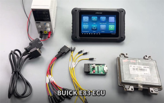
OBDSTAR DC706 Clone and Calibrate Mileage on Buick E83 ECM
How to use OBDSTAR DC706 to read and write data, read pincode, and calibrate mileage on Buick E83 ECM?
The process can be performed on the bench. Ensure you have the following tools and equipment ready:
OBDSTAR DC706 main uint
OBDSTAR P004 Adapter
OBDSTAR ECU Bench Jumper
Main Cable
High-Power Stabilized Power Supply
Buick E83 ECM
Preparation:
Ensure the ECM software is updated to 60.
Enable a stable network connection before starting the operation.
Operation:
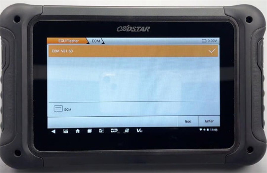
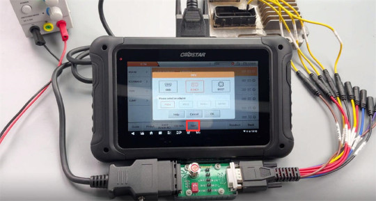
Select ECU Flasher>> ECM>> ECM V31.60
Input e83 in the search box at the top right corner to quickly find the corresponding model (BUICK ACDELCO E83 MPC5565)
Check the instruction by clicking on “Guide”
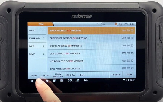
This module supports both BENCH and BOOT modes.
BENCH mode is specifically used for data cloning. If the ECU freezes, you can use the BOOT mode for recovery. The operations and precautions for both BENCH and BOOT modes are provided.
Click “Pinout”, select “BENCH” and “P004”

Check the connector pinout
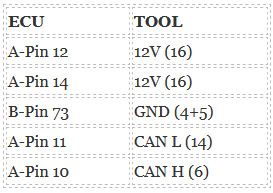
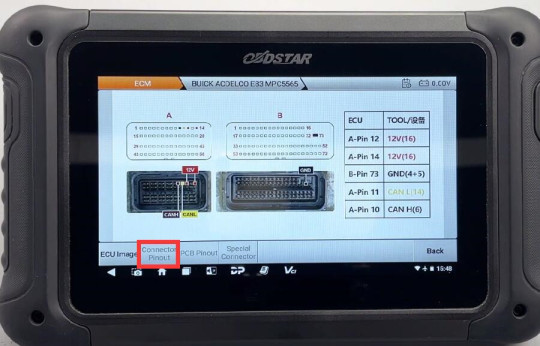
Follow the pinout to connect DC706 ECU Tool and Buick E83 ECM using P004 Adapter, ECU Bench Jumper, main cable and power supply correctly
After connection, start to perform the available functions.
Connect ECU
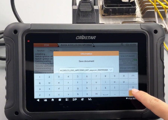
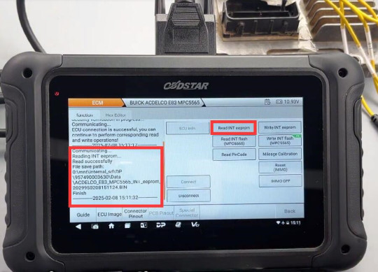
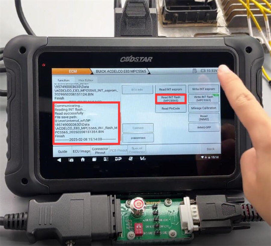
Read INT eeprom and INT flash (MPC5565)
Save the data separately. You can customize the file name, and the saving path along with operation records will be displayed on the left side.
Write INT eeprom
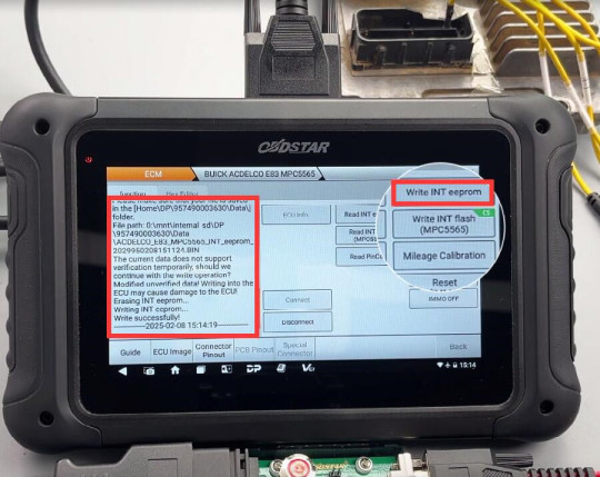
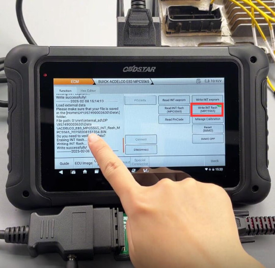
Write INT flash (MPC5565)
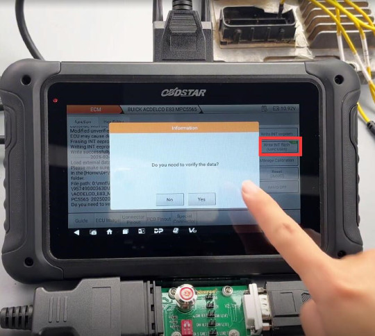
Note: The CS label at the top right indicates support data verification
Verify the data (checksum), write the INT flash data successfully
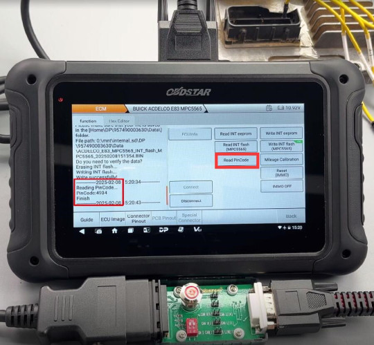
Read Pincode
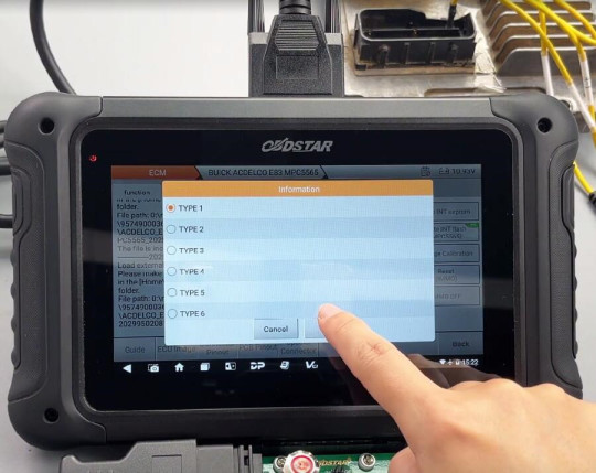
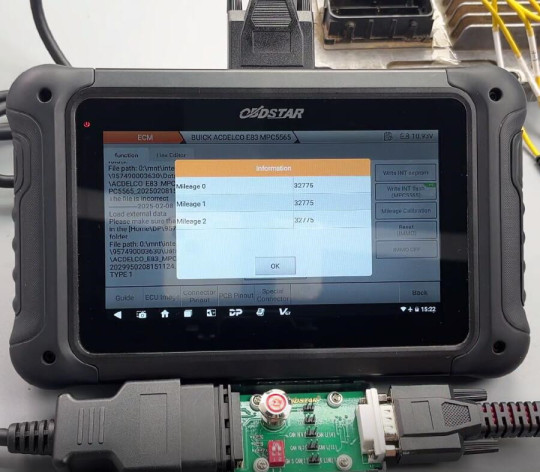
Mileage Correction
Select the type and mileage option
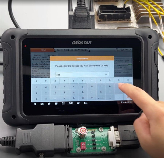
Enter the new mileage to overwrite
Save the file and write it to the ECU
Write INT eeprom successfully
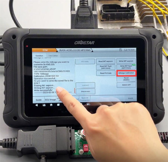
Done!
BUICK ACDELCO E83 MPC5565 reads and writes data, reads Pincode, and calibrates mileage successfully using OBDSTAR DC706 ECU Tool.
0 notes
Text
What is Device for Boot Loader Installation
When working with computer systems or embedded devices, a device for boot loader installation plays a pivotal role in initializing hardware and loading the operating system or firmware. It is a critical component for ensuring that the system starts correctly and operates efficiently. This blog will dive deep into what a boot loader is, the types of devices used for its installation, and why professional device installation services are essential.
What is a Boot Loader?
A boot loader is a small program responsible for initializing the hardware and loading the operating system kernel or firmware into the memory. It acts as a bridge between the hardware and the operating system, enabling the computer to start up and operate smoothly. Boot loaders are commonly used in:
Personal computers
Embedded systems
Smartphones
IoT devices
Without a properly configured boot loader, your device may fail to boot or function correctly.
Devices for Boot Loader Installation
Installing a boot loader requires specific devices and tools to ensure precision and reliability. Below are some commonly used devices:
1. Microcontrollers and Embedded Boards
Microcontrollers like Arduino, Raspberry Pi, and other embedded boards are often used for installing boot loaders in smaller systems. These devices enable developers to program the boot loader directly onto the hardware.
2. Universal Programmers
Universal programmers are sophisticated devices used to write boot loaders onto EEPROM, flash memory, or microcontrollers. These are widely used in professional settings for their accuracy and compatibility with various chips.
3. JTAG Debuggers
JTAG (Joint Test Action Group) devices are another essential tool for boot loader installation. They allow developers to interact with the hardware at a low level, ensuring precise configuration and debugging during the installation process.
4. USB-to-Serial Adapters
For simpler systems, USB-to-serial adapters can be used to install boot loaders. These adapters connect a computer to the target device, enabling communication and programming.
The Process of Boot Loader Installation
The installation process typically involves the following steps:
Preparing the Hardware: Ensure the target device is connected correctly to the programming tool.
Choosing the Boot Loader: Select the appropriate boot loader compatible with the hardware and operating system.
Programming the Boot Loader: Use the chosen device to program the boot loader onto the target hardware.
Testing and Validation: Verify that the boot loader works correctly by testing the system’s boot process.
This process requires technical expertise to avoid errors that could render the device non-functional.
Importance of Professional Device Installation
Professional device installation services are crucial when dealing with boot loaders. Here’s why:
Accuracy: Experts ensure the boot loader is installed correctly, minimizing the risk of errors.
Compatibility: Professionals have the tools and knowledge to select the right boot loader and installation device for your system.
Time-Saving: Avoid the hassle of troubleshooting and debugging by relying on skilled technicians.
Reliability: A properly installed boot loader ensures long-term system stability and performance.
How Techniservices Can Help
If you need assistance with device installation for boot loaders in Melbourne, Techniservices offers reliable and expert solutions. Our team has extensive experience with various devices and systems, ensuring seamless installation and functionality. Whether it’s for embedded systems, PCs, or custom hardware, we provide tailored services to meet your needs.
Conclusion
A device for boot loader installation is an indispensable tool for ensuring the smooth operation of any system. Understanding the types of devices and the installation process is essential for achieving optimal performance. However, professional device installation services can save you time, reduce errors, and provide peace of mind. Contact Techniservices today to ensure your devices are set up for success!
0 notes