#how a relay works with Arduino
Explore tagged Tumblr posts
Visit Tumblr Blog
Explore Tumblr blogs with no restrictions, modern design and the best experience.
Last Seen Tumblr Blogs


Fun Fact
69% of Tumblr users are millennials.
Text
The future of smart home control begins with one sleek, powerful interface — the Nextion NX8048P050-011R 5.0” Intelligent Resistive HMI Touchscreen. Ideal for automation projects, this display offers unmatched user experience, intelligent processing, and seamless integration. If you're planning to level up your smart home or automation setup in 2025, this intelligent touchscreen should be on your radar.
Available now at www.sonoff.in, this module is a must-have for developers, hobbyists, and smart home enthusiasts.
Power-Packed 5.0” Intelligent Display for Smart Control
The Nextion NX8048P050-011R boasts a 5.0-inch resistive touchscreen, offering sharp visuals and precise touch response. Designed without an enclosure, this screen gives flexibility in mounting it into custom panels, enclosures, or control stations.
The resistive touch feature supports usage even when wearing gloves — making it practical for industrial, automation, and DIY applications. It’s a display that adapts to your environment, not the other way around.
Advanced HMI Capabilities Built for Efficiency
This is more than just a screen. It's a powerful HMI (Human Machine Interface) equipped with:
Onboard microcontroller for fast UI rendering
Rich GUI design with Nextion Editor
Easy drag-and-drop interface development
Support for static images, buttons, sliders, and dynamic text
Integrated flash memory for storing UI pages
You can build multi-layered smart interfaces without relying on external MCUs for rendering. Control everything from HVAC to lighting systems — with just a touch.
Streamlined Communication with Embedded Systems
The Nextion NX8048P050-011R communicates using UART serial communication, making it compatible with Arduino, Raspberry Pi, ESP32, and more. Developers love how it simplifies hardware-software interaction.
Commands are sent via a simple serial interface, which dramatically reduces processing load on your main MCU. This allows developers to allocate power where it truly matters.
Why It’s Perfect for Home and Industrial Automation
Here’s why the Nextion NX8048P050-011R is a game changer:
Compact but powerful – Fits in tight spaces while delivering advanced UI functionality.
Customizable UI – Create polished, user-friendly interfaces tailored to your smart home design.
Responsive Touch – Reliable performance in both residential and industrial settings.
Highly Compatible – Works seamlessly with Sonoff smart switches and automation modules from www.sonoff.in.
Whether you’re managing lighting, thermostats, or entire smart systems, this touchscreen gives you intuitive and elegant control.
Nextion Editor – No Code? No Problem.
The Nextion Editor software is a dream for non-programmers. You don’t need advanced coding skills to build dynamic user interfaces. Just drag and drop components onto your screen canvas.
From progress bars to image sliders, your interface can be as simple or complex as your imagination allows. With built-in event triggers, automation becomes a breeze.
Technical Specs at a Glance
Let’s dive into the core specs that make this touchscreen a powerhouse:
Display Size: 5.0” resistive touch panel
Resolution: 800x480 pixels
Flash Memory: 16MB
RAM: 3584 bytes
EEPROM: 1024 bytes
MCU: 48MHz
Serial Port: TTL UART
Operating Voltage: 5V
These specifications ensure smooth performance, fast response, and consistent reliability in demanding automation environments.
Installation and Custom Integration
Thanks to its open-frame design, you can install the NX8048P050-011R in custom enclosures or panels. Whether it’s a wall-mounted control panel or embedded into a furniture piece, the flexibility is unbeatable.
Pair it with Sonoff Wi-Fi switches or smart relays to create a smart home interface that looks and feels professional.
Smart Solutions, Smarter Shopping with www.sonoff.in
Looking for a reliable supplier in India? www.sonoff.in is the trusted destination for Nextion displays, Sonoff smart devices, and complete home automation solutions.
They offer fast delivery, excellent customer service, and authentic products backed by warranty. Get access to India’s top smart home gadgets — all in one place.
Conclusion: Smart Control Starts Here
The Nextion NX8048P050-011R 5.0” intelligent touchscreen is the perfect HMI solution for next-gen smart home setups. Its seamless performance, rich feature set, and compatibility with Sonoff devices from www.sonoff.in make it a standout choice.
Don't settle for clunky switches and outdated interfaces. Take control of your environment — the smart way.
Explore the future of home automation at www.sonoff.in and power up your smart living journey today.
#sonoff#smarthome#smartappliances#googlehomeintegration#alexacompatible#sonoffpowr3#homeautomation#sonoffindia#wifismartswitch
0 notes
Video
youtube
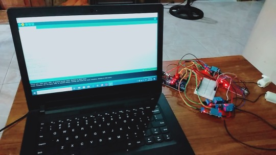
Smart Shopping Cart with Automatic Billing System through RFID and GSM | Smart Shopping Cart with Automatic Billing System | Smart shopping trolley with gsm sms alert arduino | Smart shopping trolley project report | Smart shopping cart with Automatic billing system project | Smart shopping trolley with automated billing using Arduino | Smart trolley using RFID project report | Smart shopping trolley with automated billing using Arduino ppt | Smart shopping cart project.***********************************************************If You Want To Purchase the Full Working Project KITMail Us: [email protected] Name Along With You-Tube Video LinkWe are Located at Telangana, Hyderabad, Boduppal. Project Changes also Made according to Student Requirementshttp://svsembedded.com/ https://www.svskits.in/ http://svsembedded.in/ http://www.svskit.com/M1: 91 9491535690 M2: 91 7842358459 We Will Send Working Model Project KIT through DTDC / DHL / Blue Dart We Will Provide Project Soft Data through Google Drive1. Project Abstract / Synopsis 2. Project Related Datasheets of Each Component3. Project Sample Report / Documentation4. Project Kit Circuit / Schematic Diagram 5. Project Kit Working Software Code6. Project Related Software Compilers7. Project Related Sample PPT’s8. Project Kit Photos9. Project Kit Working Video linksLatest Projects with Year Wise YouTube video Links152 Projects https://svsembedded.com/ieee_2024.php133 Projects https://svsembedded.com/ieee_2023.php157 Projects https://svsembedded.com/ieee_2022.php135 Projects https://svsembedded.com/ieee_2021.php 151 Projects https://svsembedded.com/ieee_2020.php103 Projects https://svsembedded.com/ieee_2019.php61 Projects https://svsembedded.com/ieee_2018.php171 Projects https://svsembedded.com/ieee_2017.php170 Projects https://svsembedded.com/ieee_2016.php67 Projects https://svsembedded.com/ieee_2015.php55 Projects https://svsembedded.com/ieee_2014.php43 Projects https://svsembedded.com/ieee_2013.php1500 Projects https://www.svskit.com/2025/01/1500-f...***********************************************************Creating an Arduino-based smart shopping trolley with features like adding/deleting items and auto billing with GSM SMS alert involves several components and steps. Here's a high-level overview of how you can build such a system:Components Needed:1. Arduino board (e.g., Arduino Uno or Arduino Mega)2. GSM module (e.g., SIM900)3. RFID reader4. RFID tags or NFC cards5. LCD display6. Keypad7. Load cells or weight sensors8. Servo motor (for automatic door opening, if desired)9. Relays and transistors (for controlling the door and billing system)10. Power supply11. Breadboard and jumper wires12. Shopping cart with a sturdy frameSteps to Build the System:1. Setup Arduino and GSM Module:• Connect the GSM module to the Arduino.• Install necessary libraries for the GSM module.• Configure the GSM module to send and receive SMS alerts.2. Interface RFID Reader:• Connect the RFID reader to the Arduino.• Write code to read RFID/NFC tags and associate them with product data.3. Interface LCD Display and Keypad:• Connect the LCD display and keypad to the Arduino.• Use the keypad to input item codes or quantities.• Display item details and prices on the LCD.4. Implement Add/Delete Functionality:• Create functions to add and delete items from the shopping cart.• Maintain a list of selected items with their quantities.5. Auto Billing System:• Calculate the total bill based on the selected items and their prices.• Display the total on the LCD.• Implement a billing mechanism that accepts payment (e.g., cash or card).6. Weight Sensing (Optional):• If you want to automate item addition based on weight, use load cells or weight sensors.• Add items to the cart when they are placed on the trolley, and remove them when taken out.7. Automatic Door Control (Optional):• Use a servo motor to control the trolley's door.• Automatically open the door when an item is added or when the billing process is complete.8. GSM SMS Alerts:• Send SMS alerts using the GSM module to a predefined number.• Send alerts for items added, deleted, or when the billing is completed.9. User Interface and Interaction:• Implement a user-friendly interface on the LCD for item selection, deletion, and payment.• Provide feedback and prompts to guide the user through the process.10. Testing and Debugging:• Test the entire system thoroughly to ensure all components work as expected.• Debug any issues with RFID reading, item tracking, billing, or GSM communication.11. Power Supply and Integration:• Ensure a reliable power supply for the Arduino and all components.• Integrate the system into the shopping cart securely
1 note
·
View note
Text
5V Single Channel Relay Module: A Detailed Guide
The 5V Single Channel Relay Module is a powerful and compact device that serves as a bridge between low-power circuits and high-power devices. It is commonly used in projects requiring electrical isolation or automation, making it popular among hobbyists and engineers alike. In this guide, we will explore its functions, applications, wiring, and much more to give you a full understanding of this versatile module.
What is a 5V Single Channel Relay Module?
A 5V Single Channel Relay Module is an electronic switching device designed to control high-voltage electrical devices using a low-power input. The term "5V" refers to the operating voltage required to activate the relay, while "single channel" means it can control one device or circuit at a time.
The module is widely used in home automation, robotics, and various DIY projects. Its ability to switch between circuits without a direct electrical connection makes it a safer choice for controlling high-voltage appliances.
How Does a 5V Single Channel Relay Module Work?
The relay module operates as an electromechanical switch. It uses a small input voltage to energize an internal coil, creating a magnetic field. This magnetic field moves a lever inside the relay to either open or close a circuit. By doing so, it allows or interrupts the flow of current to the connected device.
The module typically has three main connections:
Input Pins: For connecting the control signal.
Common Pin (COM): The shared connection between the relay and the device.
Normally Open (NO) and Normally Closed (NC): These determine the state of the circuit (open or closed) when the relay is activated or deactivated.
Features of a 5V Single Channel Relay Module
Low Power Requirement: Operates on just 5V input.
Isolation: Electrical isolation ensures safety between low-voltage control circuits and high-voltage devices.
LED Indicators: Built-in LEDs indicate the relay’s state, making it easy to troubleshoot.
Compact Design: Small and lightweight, suitable for various projects.
Applications of the 5V Single Channel Relay Module
The 5V Single Channel Relay Module has countless uses in modern electronics, such as:
Home Automation: Control appliances like lights, fans, or water pumps using microcontrollers or development boards like Arduino or Raspberry Pi.
Robotics: Enable remote or automated control of motors and actuators.
Industrial Automation: Automate machinery and monitor processes.
Smart IoT Systems: Integrate with IoT platforms to create smart, connected systems.
How to Wire a 5V Single Channel Relay Module
Connecting a 5V Single Channel Relay Module to a microcontroller is straightforward. Follow these steps for basic wiring:
Power the Module: Connect the VCC pin to the 5V output of your microcontroller or external power supply.
Connect the Ground: Link the GND pin of the relay to the ground pin of your controller.
Signal Pin: Attach the IN pin to the microcontroller's GPIO pin that will control the relay.
Device Connection: Wire the high-voltage device to the NO, NC, and COM pins based on your requirements.
Always ensure proper insulation and avoid direct contact with live wires during setup.
Benefits of Using a 5V Single Channel Relay Module
Safety: Provides electrical isolation, protecting the low-power circuit.
Versatility: Works with a range of devices and voltages.
Reliability: Durable and can withstand frequent switching operations.
How to Test a 5V Single Channel Relay Module
To test the module, follow these simple steps:
Power Up the Relay: Connect the module to a 5V power source.
Apply Control Signal: Send a HIGH or LOW signal to the input pin.
Listen for a Click: A clicking sound indicates the relay is switching states.
Check the LED Indicator: Ensure the LED lights up when activated.
Testing ensures the module functions as intended before integrating it into your project.
Choosing the Right Relay Module
When selecting a relay module, consider the following factors:
Operating Voltage: Ensure compatibility with your controller.
Load Capacity: Check the maximum current and voltage the relay can handle.
Channels: Choose a module with an appropriate number of channels based on your needs.
Integrating the 5V Single Channel Relay Module with Arduino
One of the most popular applications of this module is in Arduino projects. Here’s a simple example:
Components Required
Arduino Board
5V Single Channel Relay Module
Jumper Wires
Load (e.g., a light bulb)
Steps
Connect the relay module's VCC and GND to the Arduino’s 5V and GND pins.
Attach the IN pin to a digital GPIO pin (e.g., pin 7).
Write a program to toggle the relay using Arduino’s digitalWrite function.
Upload the code and observe the relay switching the connected load.
Maintenance and Troubleshooting
Regular maintenance can extend the lifespan of your 5V Single Channel Relay Module. Check for the following:
Loose Connections: Ensure all wires are securely connected.
Dust and Debris: Clean the module periodically to prevent short circuits.
Wear and Tear: Inspect for physical damage or corrosion.
If the module fails to function, verify the power supply and input signals. Replace damaged modules promptly to avoid system downtime.
0 notes
Text
Automatic Vehicle-Activated Street Light Intensity Control
Introduction to Automatic Vehicle-Activated Street Light Intensity Control How the System Works Components of the System Arduino UNO IR Sensors Relay Module Benefits of Automatic Street Light Control Energy Efficiency Improved Road Safety Applications of the System Conclusion 1. Introduction to Automatic Vehicle-Activated Street Light Intensity Control Automatic Vehicle-Activated Street…
0 notes
Text
Fixed my bike for the 50th time, also computers blow dicks
I love shit that does complex thing with simple building blocks. I have a degree in an engineering (adjacent) field, and while I utilize the skills and knowledge I acquired almost daily, what I learn time and again as I get more experience is that stuff that do one thing good are better than stuff that do many thing okay.
Usually people call it the KISS principle (keep it simple, stupid), but in this day and age I think "return to monke" fits better. Why?
Fuck computers.
This coming from a lady that works with them all the time, has her own home lab server/website/home automation/media streamer/whatever, runs arch (btw) on all her computers, and whose first instinct to solve random issues is to grab an arduino or ESP32-based board. Fuck 'em. At least, when a business tries to push one on me, fuck them in particular.
I control my arduino, I can't control some junk computer control unit in my vehicle, Xbox, air conditioner, toaster, whatever, they all universally suck! Hobbyists like me use computers to refine control of a project and make it more hackable. Corpos add computers to abstract control away from the user (really, the OWNER of the device) and make it harder to diagnose and repair.
That's why I love my motorcycle. It was made in 1981, and has exactly ONE transistor (it has electronic points, not a mechanical sparker) and the rest of the electronics is just cleverly designed relay logic and solid state components arranged in the correct order. The most complicated part is the turn signal flasher, because it relies on the signal bulbs having the right resistance to be part of a resistor divider, so no LED light upgrades, but for different reasons than a standard thermal based flasher.
The ENTIRE wiring schematic is one page! For a whole-ass motorcycle!
Anyway, I had an issue where the neutral light would sometimes come on by itself. It's a green light on the gauge cluster that let's me know the bike is in neutral, and when it's lit, it also powers a safety relay, that allows the bike to be started. It was an odd problem, sometimes it would go away, often it depend on how fast I was accelerating (more acceleration = more brighter.)
Were this a modern bike, I would be worried that whatever bullshit computer is buried in the chassis was failing, and at any point the thing could just die while I'm driving, but on my bike, I knew the issue was likely a simple exposed wire. Because the wiring diagram has ACTUAL information instead of "cable runs from computer module A to module B. Oh, what's it do? Go fuck yourself" I knew that the light turning on wasn't going to kill me, and the worst that could happen is I wear out the safety relay from repeated cycling.
Lo and behold, an exposed wire!


Clean it real good, seal it up, tape it up, and bam, no more flashy lights!
I love being able to start and finish a repair so simply, and not have to futz around for hours to figure out shit. I wish everything I buy could be this dumb.
Tl;dr: return to monke. Everything is better when it's simpler. It's better to have a thing done the dumb way by a we'll-build machine than have a piece of software try to fudge it's way to something vaugly correct. By God this bike will outlive me if I can help it.
This meme has made me feel more feelings than the ones that cracked my egg and turned me into a girl. I could rant for HOURS about how computers have ruined everything, not even from the psych "Facebook rots your brain" angle, they suck on in a technical aspect too:

0 notes
Text
Elecrow Crowbits: The Ultimate LEGO-Compatible STEM Learning System That Grows With Your Child
Elecrow Crowbits
9.00 / 10
Read Reviews
Read More Reviews
Read More Reviews
Read More Reviews
Read More Reviews
Read More Reviews
Read More Reviews
Read More Reviews
Read More Reviews
Read More Reviews
Read More Reviews
Read More Reviews
Read More Reviews
Read More Reviews
Read More Reviews
Read More Reviews
Read More Reviews
Read More Reviews

Shop Now
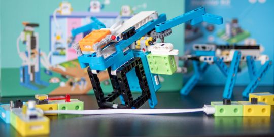
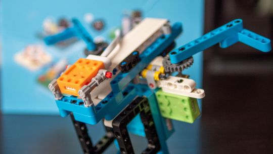
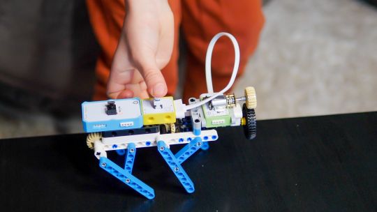
Brick builds, combined with magnetic electronics blocks, and programmable micro-controllers. Does it get any better than this? I think my long search for the perfect STEM learning kit is complete. If you have young children just coming up to the right age for it, the Crowbits system can accompany them throughout their primary education and beyond.
Key Features
Magnetic blocks build circuits
Kits to suit various levels
Specifications
Brand: Elecrow
Development Platform: Scratch and MicroPython
Pros
LEGO-compatible to customize your builds
Full range of components planned
Level up with your child with more complex projects and programmable microcontroller
Familiar Scratch-based programming software
Cons
It's a Kickstarter
Instructions need work expanding on the principles and explanations
Buy This Product
Elecrow Crowbits other
Shop
// Bottom var galleryThumbs1 = new Swiper('.gallery-thumbs-1', { spaceBetween: 10, slidesPerView: 10, freeMode: true, watchSlidesVisibility: true, watchSlidesProgress: true, centerInsufficientSlides: true, allowTouchMove: false, preventClicks: false, breakpoints: { 1024: { slidesPerView: 6, } }, }); // Top var galleryTop1 = new Swiper('.gallery-top-1', { spaceBetween: 10, allowTouchMove: false, loop: true, preventClicks: false, breakpoints: { 1024: { allowTouchMove: true, } }, navigation: { nextEl: '.swiper-button-next', prevEl: '.swiper-button-prev', }, thumbs: { swiper: galleryThumbs1 } });
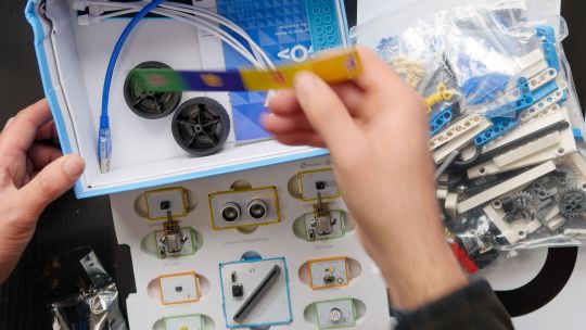
Take a moment to imagine the perfect electronics and engineering learning kit. It would be so simple even a child could use it: magnetic blocks, perhaps? Modular, so you could swap bits in and out to modify projects. It would scale up, so you could start with simple circuits and move on to programmable hardware, catering to all levels of the curriculum. Lastly, I'd throw in LEGO-compatible, because LEGO bricks are the best tool for creativity and engineering ever made.
That's exactly everything the Elecrow Crowbits system is, and it's crowdfunding now.
youtube
Disclaimer: This is a Kickstarter
Four of the five available Crowbits kits were sent to us for evaluation during the Kickstarter, however, they are still very much in the prototype stage, and we've evaluated them on that basis. Some bits were missing, some were non-functional, and the software is still a work-in-progress. This is to be expected at this stage, but the core system is solid.
Also, the usual Kickstarter caveat applies: your money is at risk, and there's no legal obligation with any crowdfunding campaign to actually deliver a product. That said, this isn't Elecrow's first campaign (the CrowPi 1 and CrowPi 2 were a huge success). It's a well-established company with a reputation to maintain and a good track record, so we think the risk is minimal.
What Are Crowbits?
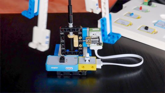
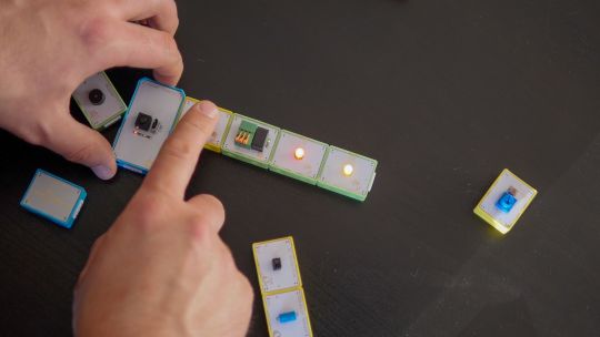
Crowbits modules are magnetic electronics blocks with LEGO-compatible pin holes on the side and stud holes underneath. The 4-pin pogo connections are either male or female, and have a small protrusion on the bottom to prevent wiring them the wrong way around.
Extension cables enable you to place a module elsewhere, and these too feature the same magnetic connection and can't be plugged in the wrong way. The whole system operates on a safe, low voltage, and with rechargeable battery blocks that charge over micro-USB.
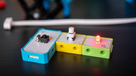
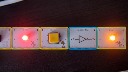
Each Microbits module is color-coded for ease of understanding:
Blue modules are power and logic. In the basic sets, these are simple battery modules that don't require programming. In more advanced sets, these are programmable microcontrollers with pin numbers on the connections for addressing modules directly.
Yellow modules are inputs: buttons, basics sensors and such.
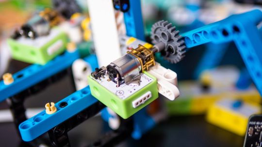
Green modules are outputs: LEDs, motors, buzzers, relays.
Orange modules are special and require serial communication lines to the programmable hub. These include things like color sensors, joysticks, or 2G communications hub.
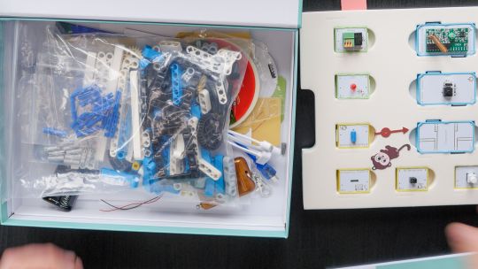
A large range of Crowbits modules are planned, though these will be available separately at a later date. For now, you can only purchase the full Crowbits kits with their included module selections.
No Programming Required!
Since the first two Crowbit kits require no programming, how does that work? Simple, as long as you follow some basic rules:
Yellow input modules must be placed on the left of green output modules (when viewed with the module name being on the top, and symbol in the bottom right).
One input module can control a chain of output modules.
A new input-output chain will be created if you add another input module to the right.
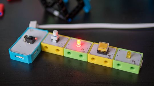
Blue battery modules can go anywhere in the circuit, and their orientation doesn't matter as long as the pins are compatible.
With this, kids can create basic circuits. For more complex circuits (that still don't need programming), a series of bitwise logic operator modules are planned. A "NOT" logic gate is included in the Hello kit, and more will be available later.
This enables you to reverse an input, such that a button that would normally turn on an LED, would now function as a button to turn the LED off.
Crowbits Kits
The Crowbits Kits are divided into five stages of increasing complexity, but all share a common system and are compatible with each other. Some modules are duplicated between kits. Let's take a look at the contents and direction of each kit.
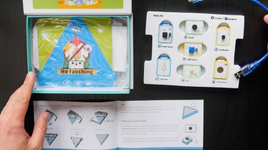
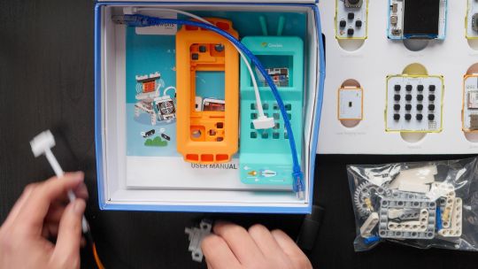
Hello Kit
The most basic of kits is also the cheapest, available for $30. It includes seven modules, one of which is a small battery module. Five project builds are included along with pre-cut cardboard parts to stick together. No programming is required, and the Hello kit is suitable for ages 5-6.
Explorer Kit
The Explorer Kit continues the no-programming theme, but adds movement through the use of a motor module and pack of technic pieces for some basic engineering. A total of eight modules are included, one of which is a medium-sized battery pack. The build guide contains a mix of brick-based and cardboard projects. With a little adult supervision on the trickier mechanical elements, 7-8-year-olds should be able to handle this kit. The Kickstarter price is $80, rising to $130 RRP.
Inventor Kit
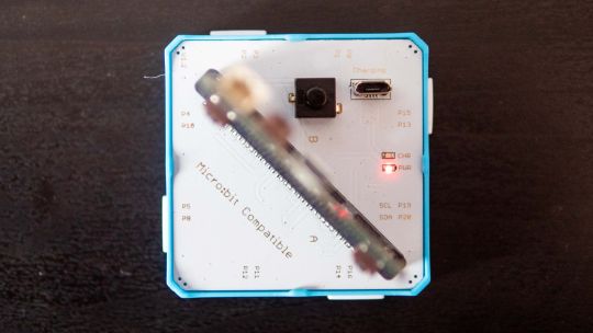
The Inventor Kit is a big step up that introduces programming concepts and more complex mechanical engineering. The main module of this kit requires a BBC Micro:bit (v1) to function. This is not included, though it may be available as an add-on if you don't already own one.
For those not familiar, the BBC Micro:bit is an all-in-one programmable microcontroller specifically designed for use in the school curriculum. It's widely used in UK schools, and gaining ground in the US.
Related: 10 Beginner Projects for the BBC Micro:bit
Ten modules are included as well as a large pack of technic bricks, suitable for building projects such as an obstacle avoidance car or color-sorting robot.
Given the use of BBC Micro:bit and Scratch programming in schools from around age 8, this kit would be suitable for 8-12 year-olds. It's available during the Kickstarter for $90, RRP $130.
Creator Kit
This was not yet ready for review at the time of writing, but the core of the Creator kit is an Arduino-based board, and includes 11 modules more suited to smart home projects and more complex interaction programming, along with a small selection of technic blocks. There are no movement motors. The Creator kit is available for $100 now, or RRP $150 later.
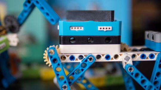
Master Kit
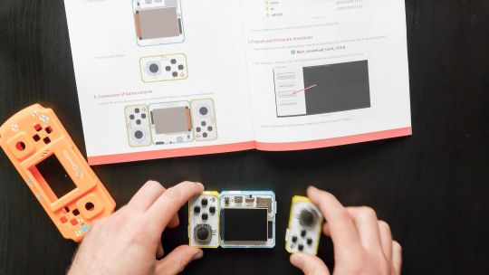
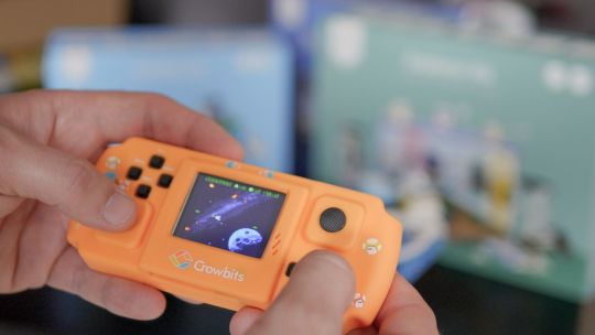
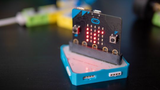
The most advanced kit in the range, the Master Kit uses an ESP32-based board at its core, featuring a TFT color screen. Also in the kit are some joystick modules, a small keyboard, laser ranging sensor, and 2G connection.
The Master Kit has a small number of technic bricks, and as well two silicone cases for a working phone, and a retro game console. It's designed to show the modules coming together to create a finished product. However, programming the firmware is quite complex, so I'd rate this kit as suitable for 14 and up. The early pricing is $100 for the Master kit, rising to $150 RRP.
LEGO-Compatible, not Actual LEGO
I should note that the Crowbits kits are not an officially endorsed nor licensed LEGO group product, and do not contain actual LEGO bricks. Instead, the LEGO-compatible technical bricks carry the brand name "CaDA", which I've not come across before.
That said, the bricks are well made and connect simply and securely, which is always a worry with off-brand construction bricks. For context, you can buy a set of at least 500 CaDA technic bricks on AliExpress for under $30.
You can of course decorate the builds with your own real LEGO, should you wish.
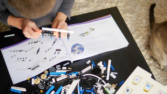
As a nerdy side-note, be warned that the instruction for the brick builds are read left-to-right, rather than top-to-bottom. If you're a LEGO family, this is mildly infuriating and means your child might skip steps!
Programming with LetsCode
Programming your Crowbits kits is done using Elecrow's new LetsCode (currently only for Windows, but support is promised for Mac OS and Raspberry Pi later).
LetsCode is a customized version of Microsoft MakeCode, which is itself based on the graphical block programming language, Scratch 3.0. As such, it'll be immediately familiar to anyone with experience of Scratch programming. It's widely used for introductory programming classes all over the world, and includes graphics blocks for all common concepts like loops, branching, and functions.
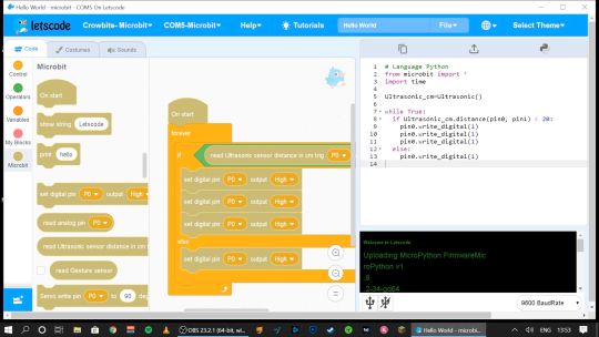
Pin numbers are printed directly on the blue modules, so it's easy to see which component is attached where.
If you outgrow graphical programming, you will also be able to program in MicroPython or Java, though this was not supported at the time of testing.
Should You Back the Elecrow Crowbits?
The Crowbits magnetic circuit system is easy to use and scales well for different ages and user levels. You can start with simple circuits, and move on to programmable logic controllers, and still reuse all the bits. It's a system that will grow with your child throughout their learning journey from age 6 to 14. Very few educational toys can make that sort of claim.
If you want your child to have a competitive edge in the programming, electronics, and engineering aspect of the STEM curriculum, then supplementing schoolwork is a great idea.
Even though many schools have now returned, it's possible you've opted to fully homeschool or just want to supplement their existing classwork. Over the next few years, schools will inevitably be different. There'll be a lot less practical work going on because of the aspect of touching shared equipment, so having this sort of kit available at home with software that's familiar will be of great benefit.
That said, the Crowbits kits vary greatly. If you're a completionist, you can grab a bargain bundle during the Kickstarter of every Crowbits kit available, for a cool $400 (rising to $600 RRP after the campaign).
But I think the best value comes from the Explorer, Inventor, and Master Kit bundle for $270. This includes a ton of mechanical bricks and plenty of movement modules. The BBC Micro:bit compatibility ties in perfectly to the existing curriculum (in the UK, anyway), while the ESP32 board is a good step up once they're old enough.
If you're only going to purchase one kit, I'd recommend skipping the Hello kit and going straight to Explorer or Inventor, depending on whether you want programming introduced yet. The cardboard projects in the Hello kit just felt a little too contrived and didn't engage my 6-year-old son in the same way LEGO does.
While the mechanical elements of the Explorer kit may need a little adult supervision, he was quite capable of the bulk of construction and able to use the LetsCode software thanks to previous experience with Scratch.
On the other end of the scale, I wasn't overly impressed with the Master kit either. The game console project, while it produces a cool end product, consists of simply the main board and two joystick modules on the side.
There is no construction, and the hardest part is loading on firmware, which tedious at best. The phone project is also impressive but limited to a 2G network, many of which will be disabled by the time the Crowbit kits ship. The ESP32 mainboard is technically impressive, but once your teenage child is ready to program this thing, the magnetic block system may not be appropriate anymore. It's a good addition to your collection if you're purchasing the earlier sets too, but I wouldn't purchase it alone.
Overall though, I think my long search for the perfect STEM learning kit is complete. If you have young children just coming up to the right age for it, the Crowbits system can accompany them throughout their primary education and beyond. And when they're done with it in a decade, we'll probably all be learning in VR anyway.
Alternatives to Crowbits
Crowbits isn't the only STEM kit around. The closest competitor is the littleBits STEAM kit, which retails at around $400, doesn't include any technic bricks, and has a limited selection of magnetic modules. It's more closely aligned to the US curriculum though with more extensive teaching materials, and already in use in many schools.
The LEGO groups' own Robot Inventor MindStorms kit is also worth considering, retailing at $350. It's focused more on robotics than basic electronics, and isn't suited to younger children, but the software is also based on Scratch. It would make a great step once your child reaches 14, and has outgrown the magnetic Crowbits system.
Elecrow Crowbits: The Ultimate LEGO-Compatible STEM Learning System That Grows With Your Child published first on http://droneseco.tumblr.com/
2 notes
·
View notes
Text
A Year of Bittersweet Capstone
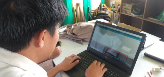
This school year has been extra challenging for us. Not just because it is our last year in high school but because of our capstone subject. Every time I hear that word, it seems very daunting and bothering at some point. Knowing that I have a few knowledge about wirings and how it works, I have already prepared myself on the amount of stress capstone may bring. As I am writing this personal blog, it amazes me on how I can look back at some of the hardest part of this school year and how I can finally say 'Salamat God kay tapos na'. My biggest achievement is finally relating to Aristotle's 'The roots of education are bitter, but the fruit is sweet.' This is truly hard yet rewarding task for all of us. I am very glad we are able to make our project as we have envisioned it to be.

Imagine if we were given the whole school year just to work on this project without other tasks, it would be the ultimate dream. Flying agricultural drones and robots equipped with artificial intelligence? If only we were given enough time for it, it would not be impossible. Of course, in reality, there are a lot more to do and accomplish in school. We had to juggle our time between doing school works for the whole day and going to a group activity for this project after school.
To be honest, I think our school is not ready for this subject and so are the students. The school is introducing robotics in the subject but there are only few teachers who are knowledgeable on programming. We cannot just solely rely on those Indian people on YouTube to teach us all of these things. Programming is new to us, especially we haven't had any computer-related subjects. We only had ICT subject when we were in 7th grade and nothing else. I also know some students in previous school years having the same subject who had the same struggle. However, since this is part of the new curriculum of K to 12, we cannot do anything but to bear with it. Also, as a student, we also wanted to do our best for the project but we lack support. It is ironic that the school is not even initiating a seminar or a workshop for programming but is having a subject for robotics. This is our struggle. I would not be shocked if other students would encounter this problem too in the next coming years. Unless the school would really take it seriously in coming up with ways on how to make students be ready and equipped for this subject and the so-called 'Industry 4.0', everything would be fine.
I salute all those programmers in YouTube who are very willing to share their innovative ideas to their subscribers. This allowed us to at least have an overview on how to properly connect and wire all the sensors. Following the instructions in YouTube was somewhat easy but programming was the hardest part since some were not willing to share their codes for the Arduino. Although they also film their codes but sometimes it is just 2 seconds of the whole instructional video. It's funny how we were so desperate to know the code that we had to screenshot some clips of the video and zoom in just to get an idea of it. We were totally clueless at the start of the year.
During our second semester, we were thankful that we had the subject Empowerment Technology. This subject was not a burden to us like how other subjects would feel like. It even made things easier for us by guiding us what to do in our projects. Calling it a blessing in disguise? I'd say yes. Our subject teacher, Sir Rae John Arango, was very willing to help us finish our project. He even set a target date for the project. I can clearly remember when he said 'Dapat before kayo magbakasyon tapos na 'yang mga projects niyo para pag Christmas wala nang problema'. Who would not want to enjoy the holidays, right? But of course, knowing that we are procrastinators, we did not meet that target date. Sir Arango still helped us program our projects despite being busy with his Continuous Improvement Project. Even if there were 11 groups for Capstone, he managed to help us all. I truly admire how he was very passionate in helping us one group at a time. To be honest, our capstone subject was only making us knowledgeable on the proper ways in conducting the research but not on how to do the actual project itself, on how to program and build the actual robot. I bet we are all very grateful that the Empowerment Technology subject are able to do this. Doing the project was somehow a lot easier for us by since our teacher was guided us on what we need to download, search for and other sensors to buy. Sir Arango is an angel sent from heaven to us struggling students or what I prefer to call 'frustrated programmers'. We owe the success of our projects to you Sir. (Sir Arango, if by any chance you are reading this, beke nemen)
We were on our track, fully confident that we are going to be able to at least start programming our project, AgriCop. When we thought everything is going in our favor, Typhoon Tisoy came. There was a blackout in our whole province. When we thought things couldn't get any worse, we were all wrong. There was no signal for us to communicate with other groupmates and to even just search in YouTube for the project. The scariest part of it is that I even had to charge our laptop using the generator while knowing the risks of the fluctuating current. I just needed to start doing the codes but then there was no internet to search for reference. We ended up doing nothing for the whole month of December. A month away from Capstone and a month before cramming and stress because of it.
Working in a group of five made it a lot easier. Although other groups have more members in their team, I mostly prefer to work in small groups. We are the only group with all girls which made it quite difficult since when need to immerse ourselves in mechanical and electronics. We are quite good in making arts and crafts, designing things, doing calligraphies and other artworks. However, this is the complete opposite of what we are used of doing. We had to let go of the paint brushes, scissors and color palettes. Instead, we learned how to properly handle screwdrivers, how to use a grinder and most especially how to solder. It was an intimidating task for all of us but we were open to learning new things. I am also grateful to my brother who taught us how to do all of these things. We did not know what tools to use but he was there to let us borrow all of the things that we needed for the project which allowed us to save a lot of money instead of buying new tools. I am so proud of what we have learned and achieved.

We were already warned by our teacher at the start of the school year that this capstone project would really be worth a lot of money. We had to save money from what my parents give as our allowance in school because sometimes it is quite embarrassing to ask extra money from my parents for this. Also, we had to buy the most basic parts first since our group did not have enough money to buy all things at once. Capstone even tested our negotiating skills since we have figured out that some of the things we have ordered were not useful for the mechatronic system of AgriCop. So, we had to sell it to other groups who needed extra relay drivers and arduino board. We were also lucky since one of our groupmates have vouchers and her shipping fee for her orders is always 50 pesos only. We also had to wait for Shopee's promo such as during 11.11 and 12.12 Christmas sale for us to get discounts. We also asked for scrap materials like aluminum tubes to reduce our expenses. Overall, we spent about 6 thousand for this robot. For me, that is already a large amount of money since it is like the salary of a normal government employee for a month of work. I am very thankful that our parents were very supportive and would understand us if sometimes we go home late just for this project. Seeing how the AgriCop works and operates is worth the amount of money that we have invested for it.

Last week has been the most tiring week in my entire existence. It was the very first time that I have experienced studying the whole day in school, going straight to our classmate's house, eating at around 8:30 or 9:00 in the evening, losing track of time, staying awake until 4 o' clock in the morning and going to school at 7:30 AM. We have gone through this cycle every day last week. It was physically and mentally draining. We also had different summative tests and projects to pass aside from the AgriCop. We did not even have the time to review or even do requirements in other subjects. Staying up late was the most challenging part of it. My father would always remind us to get enough hours of sleep but at that time we just cannot. We were deprived of sleep. The schedule of final defense was moved a week earlier than the planned date. Every single day we were required to pass different outputs in capstone. At that time there was no room for 8 hours of sleep but more space for eye bags and eye strain. We already divided the tasks for each of us. I was assigned to work on the write-up. There was this one time that I can't really handle my sleepiness anymore that I took a nap for an hour not minding how many mosquitoes were already buzzing in my ears and biting my arm. Four o' clock in the morning is our usual 'dismissal' in the group activity. We are so blessed that the father of one of our groupmates would drive each us to our houses even if it is already early in the morning. My father also does the same thing when we decided to do group activity for the last few days in our house. We are very grateful and blessed.

We have invested so much in this project, our effort, money, sleep and sacrificing time for other subjects. At some point, we felt like we were the underdog out of all the groups but I am glad that each of us did not let go of that little hope that we can pull this through. We were all tired. I saw it in the eyes of my classmates and even in my own groupmates' as we go to school in the morning after probably not getting enough rest at all. I heard their voices saying 'Di ko na aram ang uunahon', 'Papano na ini', 'Di pa ngani ako nangarigo nan nagmahaw'. We were all going through the toughest part of our life as graduating students. I always believe that the only way to overcome a situation is not to run away from it but to get through it with high hope. I am very thankful that I have groupmates who would always lift each other up and still laugh at the dumbest things that we would do at 2 AM. The perfect term to describe all of us is 'sabaw'.

We were nervous and at the same time excited during the poster presentation of our project. This was the time that we did not have any practice of our script. We just had the time to read the lines once and then the first judge already stood in front of us. We were glad that they get to appreciate our projects and made suggestions for the design of AgriCop. There was this one science teacher which was part of the judges who made me teary-eyed. Not because I was scared or intimated but because she understands what we have gone through and she was really listening and paying attention to every detail that we are saying. She told us that she really appreciates the Mechatronic System of AgriCop that is not complicated compared to other groups. She also mentioned about how it could help farmers to easily replicate our study using mechatronics. She appreciates how we put into consideration the situation of the farmers and the knowledge that they have when it comes to programming. In every word that she mentioned, I could sincerely feel her genuine appreciation to our project and how we, girls, are able to come up with AgriCop. Finally, there was at least this one teacher who can relate to all of our struggles and how hard research is. She understands our situation and acknowledges all the efforts that we have put in this project. We needed that extra boost of support at those moments. I would forever cherish all the kind words that she said to us.

The day of the final defense came. At this same day, we were also preparing for the awards in school so it made it extra hassle for us. We were practicing the script at around 10 AM and also writing down all the possible questions of the panel. I remember how nervous we were entering the STEM B room to present our project. We weren't able to finish our presentation since we exceeded the time limit and the panel already told us to show the remaining slides. The teachers were very kind to us which is the complete opposite of what we were expecting. I guess they already knew the amount of effort, money and sleepless nights we have invested for this. They commended and congratulated us for the project. They also mentioned that they witnessed how our research studies have evolved from simple studies in junior high to a research product with quality. We feel blessed that the AgriCop functioned properly and cooperated well with us. Leaving that room made us all sigh in relief. Finally, our capstone project is done. After a whole school year of working on it, it is already finished. I remember how we were all jumping around outside the room saying 'Tapos na!'. We also had a mini celebration and ate sotanghon and puto which was the food left for the panels. I can still feel that relief we all felt at that moment. A truly rewarding moment.

Capstone has been a very tough subject for all of us. We weren't prepared for it, especially in programming but we are thankful that our Empowerment Technology teacher guided us all the way. Being in a group of all girls did not became our weakness, instead Capstone allowed us to work even harder and build stronger friendship. I will leave all of the stress, rants, negative emotions, will and hopes that I have had doing this project here in my blog. As I venture more on robotics in college or in my future job, I'll look back at this and remember how we all started. I'd remind myself of a struggling student without any idea of robotics but manages to overcome it and finish strong.
1 note
·
View note
Text
Project 1 - Thermometer
youtube
Introduction –
The goal of this assignment was to use 2 or more Arduino inputs to control LEDs. To complete this requirement, I created a digital thermometer. The project currently uses a 3-LED NeoPixel strip, a potentiometer, thermistor, and a switch.
Initial thoughts –
At first, I wanted to create a heatmap using the 30-LED NeoPixel strip. Using the thermistor, I would extract the temperature map data from the different areas of contact between the thermistor and the comparison object and display this information with various lights. The issue with this idea is that the thermistor has a very small surface area, and only returns one data value, the voltage across the thermistor. There was no easy way to solve this issue, so I reworked the idea into a digital thermometer.
Implementation –
The lighting on the NeoPixels is dependent on 3 criteria: the brightness, whether the system is on or off, and the current temperature of the thermistor.
The brightness is modified using a potentiometer. A potentiometer can measure how far an object is rotated. Like the thermistor, this is just a voltage value. By using the map() function, I can align the value of the potentiometer to a range of [0, 255]. Since the maximum brightness of the NeoPixels is 255, I simply tied the brightness to the constrained potentiometer value. As a result, the user can use the potentiometer as a knob to control the LED brightness.
A switch was used to turn the system on or off. If the system is off, the LEDs can no longer light up. This acts as an on/off switch. This originally was a simple push button, but the buttons themselves were too finicky to get working.
Reflecting the temperature of the thermistor was a two-step process. First, the thermistor creates an ‘average’ temperature. This is a one-time set up done when the system is initially turned on. The program takes 10 samples and averages the values together. The sample size should be increased to get a more accurate average, but for the sake of debugging I used a sample size of 10. This, however, produced an accurate representation of the current room temperature. After the average was obtained, all other thermistor values would be compared against it. Any objects that produced a thermistor value lower than the average turned the LEDs blue, likewise any values greater than the thermistor turned the LEDs red.
Challenges and Problems-
The hardest part of this project was obtaining the average temperature. It was difficult to create an algorithm that would accurately get the room temperature, while fitting within the project’s existing code base. The current solution works but has some problems. One problem is that there is no way it can change the room temperature dynamically. So, if the room suddenly gets colder or warmer, the only way to change the room temperature is to reset the program. This can be fixed by adding reset code to the on/off switch function.
Future Improvements-
If I had something to display the temperature, like an LED screen, I would use that to actually determine the temperature of the object and relay that to the user. Currently, the program does not have this functionality, but this can easily be determined. The voltage divider between the thermistor and the circuit is given by R2 = (R1)(Vin/Vout - 1). From there, the Stein-Hart equation, 1/T = A + B ln(R2) + C ln(R2), gives the temperature in kelvin which would be converted to Fahrenheit or Celsius.
1 note
·
View note
Text
Space Image Sound - Week 8

A layout which might look similar to the final installation I created before the break to keep the gear safe during AUT Live
I haven’t been able to progress with the transistor AV switcher any further, instead over the break I researched electro-mechanical relay switches and found how much easier they are use to achieve my outcome. These switches move a contact to create a clean break in the circuit and don’t have ‘voltage leakage’ in the same way the transistor did. My circuit with the transistor could turn on and off an LED, because when it was LOW, the resistance was so high that the LED couldn’t turn on. In this case, and with the AV switcher there was still some power running through. Electro-mechanical relays are usually used with higher voltage, and I could literally run 240V through them if I wanted, however with the AV signal which runs between 0 - 1V I needed I a switch which would cleanly break the circuit as even the slightest ‘leakage’ as I was experiencing with the transistor wasn’t going to be acceptable.
https://www.galco.com/comp/prod/relay.htm

I’ve based my new AV switcher plan directly off the old version with the transistors which I’ve shown below. We are now most likely down to only five consoles, however we are still not 100% sure which ones. I was planning to buy five relays, but they only come in boards of four or eight, so I bought I board of eight and began coding and building the AV switcher. This leaves us room to expand if we want to, but if not its easy to keep it at five.

Now that I am almost done creating the AV switcher I also need to consider how to build the ‘interaction panel’ using the controllers into the Arduino. I did some research online for making the controllers work with arduino, and I found we didn’t need the USB adapters I had originally planned for and instead we could use much cheaper extension cables, and splice them into the Arduino.
Here, price started to become the limitation of what we could do -
“I just checked Trademe and to get all of the required cables and one person sells them, which is nice. Including it is shipping like this - all 7 consoles $58.60, 6 consoles (no Gamecube), $52.60, 5 consoles (no Xbox) $42.10, 4 consoles (no PS1/2 $35.20).”
To achieve this we would need a sacrificial controller cable for each console (easy to get by using extension cables for the consoles). We need a controller to USB for each console we want interactivity with. These would be soldered together (doable). Each one would run into a PC which would then need a program which reads the inputs of each controller (which we would have to code). The PC could also run audio over the inputs. Then I'd need to combine this with the digital AV switcher, which is nearly complete.
1 note
·
View note
Text
Proposal for something Awesome [EDITED - v1.1]
Topic: Facial Recognition Door Knob
My proposal for “Something Awesome Project” would be to working on “Facial Recognition Door Lock by using Raspberry Pi”.
Raspberry Pi is a low cost, credit-card sized computer that enables people to create various electronic devices, with a use of high-level programming language (e.g., Python). Ideally, it is possible to integrate it with a simple electronic circuit having relay as a main component to act as a switch to enable the door knob.
I have not had any chance to work on the project that need both software and hardware area before. So I would like to use this opportunity to work in something that I am personally interested in and to push myself forward. Here is my ideas about how it works which could be change due to the development.
With the use of Raspberry Pi (have not been finalised, might change to arduino R3 if it is better), high-level programming can be implemented on it. This can be use as a core of this project to link between facial recognition software and electronic component (door knob).
I would not finalised how the electronic component and circuit design because there are many options to be selected. So in the early state of the design, I might use an LED light to indicate the door knob functionality (for instance light-on: unlock, light-off:lock), then the circuit is going to be designed after the simple model work correctly and here is what I was thinking about in that state.
Relay module is connected into the board, this is going to act as a switch to enable/disable digital output signal which can connected direct to a door knob part.
I personally would like to use it in creating software part by using tensorflow, since I did self-study on it last year and did some simple image processing in converting hand writing into a text but have no experience in any object detection. However, if I could not do it, OpenCV (I have no experience) is my second plan in creating software part.
Planing
I wish to set out the working on my project as follows
Weeks 3: Doing research about facial recognition API and design the circuit.
Weeks 4-6: implementing software part for facial recognition and electronic circuit (with Raspberry Pi, external camera and relay module integrated.)
Weeks 7-8: Unexpected problems and finishing up
Stages and Milestones. [EDITED]
Basic Goals.
Implementing facial recognition software
Creating simple designed electronic model of Raspberri Pi to run the software above
Extension
Uploading progress and demonstration of the facial recognition in each iteration
Writing tutorial and guide on how to build it.
Marking Criteria [EDITED]
Although I have some knowledges about electronic circuits, I have never worked on any practical hardware project before. I could not confidentially ensure that the project would be eventually end up with well-functioned facial recognition uploaded into electronic circuit board that work correctly with the user. So I have created my marking system.
FL - No attempt
PS - Minimal attempt in the project.
CR - Consistent blogs every week in updating what I have done on doing research and how I manage to design the circuit and software implementation.
DN - Either electronic circuit or software is complete but might not work properly (For example, the software works on laptop but not work on the circuit since the different in version or operating system on the board).
HD - The electronic circuit connect to all the component and be able to work with facial recognition software to enable the digital output signal. An extension part is finished.
1 note
·
View note
Text
Uv things, Finally Moving Forward.
https://www.trademe.co.nz/electronics-photography/other-electronics/electronic-components/other/listing-2154965780.htm?rsqid=4b3da0615d10475c96fff6474527aa46-002Today, we all met earlier at the cafe outside of the WF building, The Counter, we continued to discuss more ideas that our project could possibly be. Over the weekend, Nathaniel suggested an idea of setting up a photobooth type station which would have happy innocent infographics with all the benefits of the internet all over the walls, then with a flick of a switch we would activate a UV light bulb which has all these horrible infographics all over in messy writing that are creepy or disturbing facts all about the bad things that is allowed and/or caused by the internet. This could be things such as online predators, drug dealing, the dark web, companies stealing away our privacy. While talking, I suggested a full-on experience inside this photobooth. Our users would walk inside the photobooth, and sit down in front of a simple laptop on top of a desk. There could either be some happy video playing on the laptop or some kind of interactable experience, there would also be happy facts all over the walls in the photo booth. Then, we would flick a switch which would cause the UV light bulb to turn on, revealing horrible and terrifying facts about the dark web and the kind of things that the internet can cause, such as catfishing. Then, the laptop could start flickering or start playing some kind of creepy video which is meant to make the user feel uneasy. Did you know that scorpions glow under UV light? We just figured that out today. We keep thinking of projects that relate to UV, so Roxy and I did some research of things that glow under UV to get some ideas flowing of how we could possibly pull off some of the ideas that we keep thinking of. I did some quick google searching, I found this UV bulb from bunnings that we were very surprised about since it was much cheaper than expected: https://www.bunnings.co.nz/nelson-20w-es-cfl-ultra-violet-party-light_p00389303 After talking to Krishna he gave us all the knowledge we would need to make the UV light bulb turn on and off at specific times, here is a quick list of things we would need: Solid state relay (SSR) Electronic Switch - https://www.trademe.co.nz/electronics-photography/other-electronics/electronic-components/other/listing-2153851819.htm?rsqid=5111aa8a25564224a33f5202695997a4-002 Arduino Uno - https://www.trademe.co.nz/electronics-photography/other-electronics/electronic-components/other/listing-2154965780.htm?rsqid=4b3da0615d10475c96fff6474527aa46-002 We spoke to Charles and told him everything about our project that we were thinking of doing, he pretty much made us realise that not only would this original idea be something which would be out of our grasp as it would take too long to complete but the resources needed would be hard to get. On top of all of this, he told us that usually, lecturers don’t like to go into a segregated space which totally made sense to us and something I was personally worried about when we first came up with this idea. We took Charles advice and used it to construct more efficient ideas and it resulted in us to scale down what we have. Now we’re thinking of this wooden black box with a curtain on it that you stick on top of a table, people still get the same experience but instead of this huge photo booth type thing, it’s a much more convenient and easier way of doing it. I suggested we could have this video (playing of all the benefits of the internet, we could use stock footage or get our own) on one of our laptops inside this deep dark box, it would last maybe 30 - 60 seconds, then once it finishes we would tell them to watch it again, this time the audio is different, the video is the exact same but the audio is dark and creepy, instead of the benefits, it’s talking about the dark side of the internet but still using the same shots so it’s contrasting them to each other. We would do this to reveal to our audience that there is just as much bad (if not even more) from the internet than it is good. Roxy added the idea of also handing them a UV flashlight when the video changes, and there would be disgusting and horrifying facts inside this dark box which they couldn’t see without the torch. This is to enlighten our audience so they know all the dangers that lurk in the deep dark web. Through this conversation, we have finally got our method/intent and here it is: Our project’s aim is to reveal the sinister side of the internet through an isolated immersive experience that dramatically unveils the unknown through multiple mediums. Yvonne came to speak to us, and I was initially scared, but after telling her about our new idea, she loved it and started suggesting more things that could possibly work, such a making the box a teenagers bedroom, then sliding in other parts as the story goes on. I’m excited to start prototyping tomorrow and make some more progress.
1 note
·
View note
Video
youtube
AUTOMATIC IRRIGATION SOIL MOISTURE CONTENT CONTROL | Auto Irrigation using Soil Moisture Sensing | Automatic Irrigation System Using Soil Moisture Sensor | Smart Irrigation Technology Controllers and Sensors | plant watering system with new blynk update | plant watering system | plant watering system using nodemcu and blynk | plant watering system using iot | smart irrigation system | smart plant watering system.***********************************************************If You Want To Purchase the Full Working Project KITMail Us: [email protected] Name Along With You-Tube Video LinkWe are Located at Telangana, Hyderabad, Boduppal. Project Changes also Made according to Student Requirementshttp://svsembedded.com/ https://www.svskits.in/ http://svsembedded.in/ http://www.svskit.com/M1: 91 9491535690 M2: 91 7842358459 We Will Send Working Model Project KIT through DTDC / DHL / Blue Dart / First Flight Courier ServiceWe Will Provide Project Soft Data through Google Drive1. Project Abstract / Synopsis 2. Project Related Datasheets of Each Component3. Project Sample Report / Documentation4. Project Kit Circuit / Schematic Diagram 5. Project Kit Working Software Code6. Project Related Software Compilers7. Project Related Sample PPT’s8. Project Kit Photos9. Project Kit Working Video linksLatest Projects with Year Wise YouTube video Links157 Projects https://svsembedded.com/ieee_2022.php135 Projects https://svsembedded.com/ieee_2021.php 151 Projects https://svsembedded.com/ieee_2020.php103 Projects https://svsembedded.com/ieee_2019.php61 Projects https://svsembedded.com/ieee_2018.php171 Projects https://svsembedded.com/ieee_2017.php170 Projects https://svsembedded.com/ieee_2016.php67 Projects https://svsembedded.com/ieee_2015.php55 Projects https://svsembedded.com/ieee_2014.php43 Projects https://svsembedded.com/ieee_2013.php1100 Projects https://www.svskit.com/2022/02/900-pr...***********************************************************1. How to make Automatic Plant Watering System using Arduino UNO and Soil Sensor,2. Water Your Garden with IoT - Soil Moisture Sensors,3. Automatic Irrigation System using Soil Moisture Sensor,4. Smart Irrigation || Automated irrigation process using Arduino Moisture sensor and water pump|| IoT,5. How to make Automatic Irrigation System using Soil sensor,6. Capacitive Soil Moisture Sensors don't work correctly ESP32 Raspberry Pi,7. Soil Moisture Sensor with Arduino Uno,8. Agriculture Projects: AUTOMATIC IRRIGATION WATER SUPPLY MONITORING AND CONTROL SYSTEM,9. Automatic Irrigation System using Soil Moisture Sensor,10. How to make Automatic Agriculture System project | Smart Irrigation System | mini project idea 2023,11. IoT Based Smart Agriculture Automatic Irrigation System with ESP8266,12. Smart Irrigation System | Arduino Uno | DHT11 | Humidity Sensor | Soil Moisture Sensor | Relay,13. Smart Irrigation System | Arduino | Soil Moisture Sensor | Relay | DC Water Pump | Arduino Projects,14. How to build a IOT Smart Irrigation System with Blynk, NodeMCU, and Soil Moisture,15. Auto Irrigation using Soil Moisture Sensing,16. IoT Based Plant Watering System Indoor project using ESP32 Blynk | IoT Projects 2023,17. Automatic Watering System sensors kit | Mini water pump, Battery Case, Soil Moisture Detector Module,18. IRRIGATION WATER SUPPLY MONITORING
0 notes
Text
A Semi-Automatic Turntable: Part 1
Part 1: Intro & Subsystems
For a while now, I've been considering using an Arduino in order to automate the operation of the turntable on my layout. After considering several 'bolt-on' additions, I realised that trying to add indexing to the existing, DC-motor mechanism would be cumbersome. As such, I decided to replace the drive mechanism with a stepper motor, and use that for indexing.
My original plan was to just add indexing, with a keypad to select the desired track. But then I realised that I could take it a step further, and make it fully automated. This didn't quite work out, and I instead ended up with a semi-automatic version. This is how it ended up working:
youtube
I decided on this approach for two reasons: 1) I couldn't find sensors which would give me the accuracy required while being hidden. That is, there was always a trade-off between accuracy and visual impact. 2) My layout is a backwoods operation, with operating ground throws to change the turnouts.
As such, I wanted to have a hands-on element to the turntable's operation. While testing the fully automatic version, I found that I felt a bit 'disconnected' from what was happening. So in this series of posts, I'll be covering how I built this final version, and some of the things I learned along the way.
This first part will cover the construction and testing of the subsystems that make up the turntable controller. Some of these were built or adjusted after I'd decided to go from a fully automatic to a semi-automatic system.

I started by working out how to operate the stepper motor, a 12-volt NEMA-17 motor. This was the key to the whole system, and I'd never used one before. In order to drive it, the Arduino controls an A4988 chip. This is the red board in the photo above, with a silver heatsink on it. It takes a control signal from the Arduino, and a completely separate power supply for the motor itself. The only additional component required is the capacitor, to protect the inputs for the motor power supply, as well as a 10K ohm resistor to hold down the motor step pin when not in use.
The A4988 offers the option to drive the motor in 'microsteps', in which each pulse moves the motor by a fraction of a full, 1.8-degree step. Pins MS1, MS2 and MS3 on the A4988 are used to set which fraction is used. Setting them high, in various combinations, allows the A4988 to drive the motor in increments as little as 1/16 of a step. At this point in the build, I wasn't sure what resolution I would need. As such, I added a 4-way DIP switch between these three pins and the +5v rail, to allow me to try them. One of the switches from the DIP switch wasn't used.
Working from what I'd worked out on the breadboard, I built a motor driver board to be used in the final build.

My next step was to test that the motor had enough torque to move my locomotives. My heaviest locomotive is my boxcab, which was built on an Athearn blue-box mechanism. As such, it weighs in at around 450g.

I cut a length of wood to the same length as the turntable bridge. After finding the centre, I attached the driveshaft adapter I'd had 3D-printed by Shapeways. This fits around the shaft of the stepper motor, with a flat section where the drive shaft is flattened. It took a few tries at different sizes before it fit perfectly.

To simulate the load, I used a box of old motors I'd bought at a sale at my model train club. They were the only thing I had to hand which were heavy enough. I taped them to the top of the board, until it weighed 500g (for a bit of wriggle room). I then placed it on the end of the driveshaft.
youtube
The motor was able to move the load without any problems. With that confirmed, I started working on the components for the control panel.
The original, fully-automatic design had two 3mm LEDs on it, one red and one green. These were to have been 'stop' and 'go' signals for when the automated turntable was operating. The other component for the control panel was a 4-digit LED display to show the address of the currently selected locomotive. Owing to the change in focus for this project, the design of the control panel changed slighlty between the initial and final versions. But before I could build it, I needed to build the 4-digit LED display.

I'd done one of these on the base station for my DCC system. On that occassion, I'd made the display from four individual 7-segment displays, driven my a MAX7219 LED driver chip. This time around, I decided to use a 4-digit display, driven by the same chip. With the four digits in the one package, it only needs 12 connections for full functionality. I wired the 4-digit display to the MAX7219, leaving out the connections for the decimal points between the digits. They weren't needed.
To test it, I wrote an Arduino sketch (program) that counted up to 10,000 in 0.01 second increments and ran it. I was able to re-use a function I'd written for the base station, which will take a number up to 9,999 and display it across the four digits of such a display.
With that done, I was able to build the control panel itself.

When I decided to go from automatic to semi-automatic operation, I replaced the red LED on the panel with a single-pole, double-throw momentary contact switch. This is used to turn the turntable, via the stepper motor. I'd used a length of Cat5 network cable to connect the control panel to the Arduino, to keep things organised. This had a spare wire left in it. As such, I was able to wire the switch to the ground connection, then use the original wire for the red LED and the spare wire to connect to each side of it.

In order to get the program to work properly, there are a couple of points at which it pauses to prevent a false triggering while the locomotives move on and off the turntable. After initial testing, I realised it would make things clearer if there were an indication of when these pauses were occurring. So I added a yellow LED to the control panel, to indicate when the system was active. If this LED is on, then the turntable can be turned, locos can arrive and depart, etc. If it's off, then the system is paused.
Once completed, this control panel was installed in place of the original control panel on the fascia. The original panel had just had two switches, a DPDT rocker to control the DC turntable motor, and a 12-position rotary switch to select track power.

Next up was the occupancy detector, to determine when a train was on the bridge. The design of this turntable provides constant power to the tracks, with an auto-reverser reversing the polarity as needed. After a bit of experimentation, I found that wrapping the wire at least four times through the coil was enough to allow it to detect the current of a sound decoder at idle. At least, that's what I thought.
It's the first time I've used a coil like this, and it was sold amongst other Arduino modules. As such, I thought I would be able to plug it straight into an analog pin of the Arduino, and take a reading from that. This was not actually the case. As DCC is very close to AC current, I ended up getting several values from the coil over the course of a second, including 0, which would create false negatives. After asking about this on the Arduino forums, I learned that the way these coils work is by generating AC current, in response to the current going through them. I thought they just sensed it. As such, I'd accidentally been putting 38v of AC into the analog pin I was using, and had damaged it.

In order to use the coil for DCC occupancy detection, some supporting circuitry is needed. I found this article here, outlining how to build a sensor out of such a coil. I didn't have the exact same transistor, and instead used a BC548 NPN general-purpose transistor. The yellow wires off the board go to the two sides of the coil, and the green one goes to the Arduino.
Once I'd built this, I tested it with my locomotives before connecting it to the Arduino. This was where I discovered something interesting. The circuit is designed to give a digital output, in which anything less than 1.5v on the Arduino pin is counted as a 0, and anything above it as a 1. When testing it, I found that it produced an output of 3.7 volts when no locomotive was present, and that this dropped when one was detected. However, about half of my locomotives only dropped it to a value above the 1.5v required for a digital 0, yet less than the 3.7v of the 'nothing detected' state. As such, I connected it to another analog pin on my Arduino. These voltages translated to an analog read value above 900 when nothing was detected, and below 900 when something was. Thus, I used an analog reading with a threshold of 900 in the program function to detect occupancy.
At this point, the next item to be tested was a socket for an XBee wireless module. I'd already used these to make my DCC system, as well as to transmit the address of the incoming locomotive to my automated staging controller. As such, I pulled out a spare XBee, and configured it identically to the one for the staging controller. It'll be used for the exact same purpose, receiving addresses when a locomotive is dispatched. I tested it by connecting it to the Arduino, then rigging up the Arduino to display the received locomotive address on the LED display.

The next step was to prepare the Arduino shield. I usually use prototyping shields for the connections to the Arduino, as this means that I can just unplug the shield and pull the Arduino out if any software updates are needed. I've found it's easier to solder two wires together under the layout, than it is to solder to a shield. So I added small lengths of decoder wire to each output.
My turntable has 11 tracks around it, and I didn't have 11 spare pins on the Arduino. Instead, I used a 16-channel multiplexer with channels 1-11 wired to a bank of relay switches. I started counting at channel 1 instead of 0 in order to make the software code a bit simpler. The resistor on pin 4 is 220 ohms, and is connected to the green LED on the control panel. At this point, I hadn't added the yellow LED to the control panel. When I did, I added a 220 ohm resistor to pin 13, and connected this LED in there.
The other component of note is the variable resistor connected to pin A1. I was originally going to have a light detecting resistor in the turntable lead track, to trigger the Arduino when a train was leaving or arriving. However, after getting the occupancy sensor working reliably, the LDR was no longer needed.

The final building block was the relay bank. I'd bought a 16-relay module off eBay, and I installed it behind the fascia, next to the control panel. The wires from the original 12-way rotary switch to the tracks came out here, so by putting it in this position, I didn't have to do too much in the way of rewiring. Each track was wired to the normally-open contacts on the first 11 switches, with wires from the common side of the relay going to the track bus. The multicoloured ribbon cable on the far side of the relay bank goes to the Arduino, with two wires for the power supply and the other wires for the track control.
With all the building blocks worked out, the next step was to install the stepper motor and modify the turntable. This will be covered in part 2 of this writeup.
4 notes
·
View notes
Text
Reason core security serial

#Reason core security serial serial#
#Reason core security serial password#
It will not work with Tasmota binaries compiled with 2.6.0 or later. This tip takes advantage of a security risk present in Arduino Cores prior to 2.6.0.
#Reason core security serial password#
If you flashed a light bulb or any device without a built-in button and entered wrong Wi-Fi password you now have a device that won't connect to your Wi-Fi and you have no button to force it into Wi-Fi configuration mode.
Access your device and set the correct Wi-Fi credentials.
After getting the incorrectly entered configuration from this URL, configure an access point with these settings as described above.
h is the hostname given to the device by the Tasmota configuration.
s2 and p2 are the same parameters but for the second AP.
There should be an entry similar to this:
Search in your browser history for 192.168.4.1 (or whatever address you used for configuring it).
Since Tasmota uses GET request for forms, the password may be in your browser history.
#Reason core security serial serial#
If these methods don't work, it may still be possible to save the device without opening it to perform a serial flash. You should see your mis-configured SSID fairly soon. Plug in the mis-configured device and immediately watch SSIDs. For example Nirsoft WifiChannelMonitor can show your mistakenly configured SSID name. If you are unsure what SSID you have entered, you can try to find that with special Wi-Fi sniffing tools. If that didn't work reset your device using Fast power cycle device recovery Note: Since version 8.3.0 this requires 6 short presses instead. If you have a device with a button and the button is configured as a component in the Tasmota settings (e.g., GPIO0 - Button1), you can try pressing the button to force the device into Wi-Fi configuration mode with 4 short presses of the button. Disabling OFDMA can solve problems with WiFi failing to connect. Some Tasmota devices also have issues with OFDMA (WiFi 6) enabled on the 2.4GHz band. Disabling WMM can resolve connectivity issues. Moreover, you probably should disconnect 5GHz radio during the configuration process.ĭD-WRT also has Wi-Fi Multi-Media (WMM) enabled by default. Linksys with DD-WRT), you may have conflicts with the 5GHz radio. Other reason can be using an SSID longer than the allowed 32 characters. If your device does not connect to your Wi-Fi and you've made sure the Wi-Fi credentials are correct, it is caused by using special chars or white spaces in your SSID or Password of your Wi-Fi. Can you add this unsupported sensor to Tasmota.Sonoff 4CH V2 / Sonoff Dual V2 will not flash.There was white smoke and the device does not work anymore!.How do I invert the output of the green LED on the Sonoff Basic so the LED is on when the relay is off?.Why is my changed configuration not loaded?.Auto-discovery in Home Assistant does not work.Tasmota is sending many status updates every 5 seconds.Device keeps restarting after changing config over MQTT.My device randomly switches on and off.Relay clicks and LED flashes at 1 second intervals.WebUI unavailable but device can be controlled.VL53L0X and VL53L1X laser ranging modules.RCWL-0516 microwave radar motion sensor.MLX90640 Far infrared thermal sensor array.MGC3130 3D tracking and gesture controller.Honeywell HIH temperature and humidity sensor.BME680 temperature, humidity, pressure and gas sensor.BME280 temperature, humidity and pressure sensor.AHT1x/AHT2x and compatible temperature and humidity sensor.Smart Home Integrations Smart Home Integrations.
0 notes
Text
Channel Relay Module: Everything you need to know
The 4 Channel Relay Module controls high-voltage, high-current load such as motor, solenoid valves, power lamps, and AC load. The 4 Channel Relay Module comprises four 5V relays and the associated switching and isolating components, making the interfacing with a microcontroller or sensor easy with minimum features and connections.
Relay modules can be used across industries, including process technology and power engineering, railway applications, machine engineering, and general control cabinet construction.
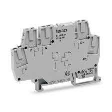
Technical Data
• Number of digital outputs: 4 • Total number of channels (module): 4 • Actuator connection: 4 x (1-wire) • Output circuit design: 4 make contacts Relay • Output characteristic: potential-free • Switching frequency (max.): 0.33 Hz; 3 A / 250 VAC, 30 VDC • Switching frequency (max.) (2): 0.1 Hz; 5 A / 250 VAC, 30 VDC • Load type of switching frequency: 3 A / 250 VAC, 30 VDC • Switching voltage (max.): 250 VAC; 30 VDC; 110 VDC at 0.4 A • Switching current (max.): 2A • Switching current (note): 5 A for single-channel use • Switching power: 1250 VA / 150 W; cos ϕ max. = 0.4; L/R max. = 7 ms • Pull-in time (max.): 10ms • Drop-out time (max.): 5ms • Bounce time (typ.): 1ms • Electrical switching operations (min.) (at max. resistive load): 100 x 10³ switching operations • Mechanical switching operations (min.) (at max. resistive load): 20 x 10⁶ switching operations • Output data width (internal) max.: 4bits • Supply voltage (system): 5 VDC; via data contacts • Current consumption (5 V system supply) 95mA • Isolation: 1500 V (system/field) • Indicators: LED (A-D) green: Status relay 1 … relay 4
Features
• Input supply 12 VDC @ 170 mA • Output four SPDT relay • Relay specification 5 A @ 230 VAC • Trigger level 2 ~ 5 VDC • Berg pins for connecting power and triggering voltage • LED on each channel indicates relay status • Power Battery Terminal (PBT) for accessible relay output and aux power connection • Four mounting holes of 3.2 mm each • PCB dimensions 88 mm x 68 mm
Four-Channel Relay Module Usage
The most significant advantage of the 4 Channel Relay Module is that it can switch multiple loads at the same time due to four relays present on the same module. This type of relay module provides the perfect solution for home automation. It can be placed in the main switchboard, connected to loads in other parts of the house, and controlled from a central location using a microcontroller.
Benefits of Relay Modules
• Electromagnetic relays have a fast process and speedy reset • They can be operated for both AC and DC systems for the safety of AC and DC equipment • Electromagnetic relays operate at speeds that can manage in milliseconds and are also possible • Relay Modules are simple, robust, compact, and reliable • These relays are almost instantaneous. Though quick, the operating time of the relay varies with the current. With different setups like dashpot, copper rings, etc., slow operational duration and reset can be possible.
How does it work?
This relay module has three high voltage terminals (Normally Closed (NC), Common terminal (C), and Normally Open (NO)) that attach to the device you want to handle. The other side has three low voltage pins (Ground, Vcc, and Signal) that join Arduino.
0 notes
Text
FINAL
470 Final “Kilroy was here!” Daniel,Reese,Ben


Statement of Experience Goal
Our goal was to have a mysterious and fun experience where individuals would find the “Kilroy was here” box and be able to push a button on the box. This would send a message to the server relaying how many individuals found Kilroy at a specific location. The box would then be physically moved and the message updated to the new location.
Summary
Our original goal was going to develop a device based on the Kilroy mythos of WW2. Considering the original “meme” “Kilroy was here” was a character that United States soldiers often wrote/etched on the walls of buildings and structures that they came across. It was a form of entertainment for many of the American soldiers who found themselves depressed and in low morale as the war went on. It’s important to note that Kilroy was also used as a symbol of pride and accomplishment. Kilroy was here often marked as a territory that had been liberated by United States soldiers. Reconnaissance units used it as a means to communicate to soldiers that this area had been scouted out. In the end “Kilroy was here”, become a message to all those who opposed the united states a nice warning that there was no country beyond the reach of the united states
Narrative,issues,discoveries,results
Originally, we were going to use firebase as a means of storing data from our Arduino. This would have been our server and would keep track of the number of times Kilroy was found in a specific location. We would use a web page of our own creation in order to present this data to users. Users would be able to access this data via a QR code. Our hopes of constructing our project in this manner were dashed when we could not get our Arduino to correctly connect to firebase in order to upload the data. We searched for varying means of constructing a server that our Arduino could use to store the data but couldn’t find or get any of the subsequent servers working. Eventually, we would move on from attempting to get server communication working/ database communication working. Instead, we will be using Thingspeak in order to get the Arduino to communicate with Twitter. Our Arduino would send a text to Thingspeak which in turn would convert our text into a post that would be published on Twitter. Informing any followers that Kilroy was found in a specific location. Eventually, this is how we got it working.
Process
After confirming that we could use Thingspeak as a way for an Arduino to post messages to Twitter. We got started on a way the user could interact with our Arduino to send the messages. Originally we would be doing this through buttons. Where the user would press a button after which the Arduino would send a message to Twitter stating where “Kilroy was found at (blank)” depending on the hardcoded location we would have for that day. This message would then get tweeted. Although we had problems with our button not reading correctly(possibly fried?). Regardless, we quickly swapped to use velostat where the user would simply press the nose of Kilroy to tell the Arduino to tweet the location message.
Diagram Fritzing
Code
https://pastebin.com/wCUAbe7b
Citations
ThinkTweet
https://thingspeak.com/login?skipSSOCheck=true
Additional Kilroy information
https://www.thoughtco.com/killroy-was-here-4152093
0 notes