#4 Channel Relay Module
Explore tagged Tumblr posts
Visit Tumblr Blog
Explore Tumblr blogs with no restrictions, modern design and the best experience.
Last Seen Tumblr Blogs


Fun Fact
Tumblr Inc. is funded by 13 investors.
Text

The TTP224 is a 4-Channel Touch Sensor, meaning it has four touchpads. Whenever a capacitive load such as human hands is brought in proximity with the sense pad, the sensor then senses the change in capacitance and activates the switch. Custom sense-pads can be made from nearly any conductive material and these sensors can detect touch through thin layers of non-conductive materials such as glass, plastic, fabric or even wood. Each Touchpad has its respective output pin when the user touches a pad, the corresponding output pin will go high. It is very easy to interface with microcontrollers like Arduino to control different applications as a switch. It can be used in home automation, motor control, Relay control, etc. the module basically gets rid of the push button troubles.
6 notes
·
View notes
Text

ARM Embedded Computer for Building Security and Surveillance Systems
ote viewing.
Access Control:
Hardware: X-board (RS485/RS232) connects RFID readers, Y-board (DI/DO) controls locks; Ethernet/4G for networking.
Software: BLIIoTLink integrates Modbus/MQTT, Node-RED for access logic.
Application: Face/card-based door access, events uploaded to property management platform.
Intrusion Detection:
Hardware: Y-board connects PIR/vibration sensors; NPU analyzes anomalies.
Software: Node-RED processes sensor data, MQTT uploads to cloud.
Application: Detects unauthorized entry, reduces false alarms with video integration.
Alarm Function:
Hardware: Y-board (relay/PWM) controls buzzers/lights; 4G for notifications.
Software: BLIIoTLink sends alarms to SCADA, BLRAT for remote management.
Application: Triggers sound/light alarms on anomalies, notifies security personnel.
3. Recommended Configuration
Model: BL372B-SOM372-X23-Y24-Y11
3x Ethernet, 32GB eMMC, 4GB RAM, 4x RS485, 4x DI/DO, 4x relays, 8x DI.
4G/WiFi module, Ubuntu 20.04, BLIIoTLink + Node-RED.
Reason: Meets multi-channel video, access control, sensor integration, and cloud communication needs.
4. Advantages
High Performance: NPU + 2.0GHz CPU supports AI and video processing.
Flexibility: Modular I/O adapts to various devices.
Industrial-Grade: Wide temperature range, anti-interference, suitable for building environments.
Easy Development: Node-RED, Qt, BLRAT simplify development and maintenance.
5. Challenges and Solutions
Limited Processing Power: Optimize AI models or add external accelerators.
Network Disruption: Local caching + resumable transmission.
Security: TLS encryption + watchdog protection.
6. Summary
The BL370 efficiently implements video surveillance, access control, intrusion detection, and alarm functions for building security with high-performance hardware and flexible software, suitable for commercial, residential, and industrial scenarios. The recommended BL372B configuration supports rapid deployment and cloud management.
0 notes
Text
Solid state relay module, High voltage relays, what is solid state relay
CPC1035N Series SPST 100 mA 350 V Single Channel Solid State Relay SMT - SOIC-4
0 notes
Text
5V 4 Channel Relay Module
Reliable 5V 4 Channel Relay Module for Automation Projects Introduction to the 5V 4 Channel Relay Module Features of the 5V 4 Channel Relay Module Applications of the 5V 4 Channel Relay Module Technical Specifications How to Use the 5V 4 Channel Relay Module Frequently Asked Questions (FAQs) Related Products Introduction to the 5V 4 Channel Relay Module The 5V 4 Channel Relay Module is an…
0 notes
Text
Controlling Multiple Relays with Arduino: A Comprehensive Guide
Introduction
Relay modules are essential components in the world of electronics, allowing you to control high-power devices with low-voltage signals. When combined with the versatility of Arduino, you can create a wide range of automated systems. In this blog post, we'll explore how to control multiple relay modules using an Arduino board.
Understanding Relay Modules
A relay module typically consists of one or more relays, each with a control pin and a pair of output terminals. By applying a low voltage (usually 5V) to the control pin, you can switch the relay, connecting or disconnecting the output terminals. This allows you to control devices that require higher voltages and currents than the Arduino can directly provide.
Required Components
Arduino board (e.g., Uno, Nano)
Relay module (2-channel or more)
Jumper wires
Breadboard (optional)
Power supply (5V DC)
Circuit Diagram
Power Supply: Connect the 5V and GND pins of the relay module to the 5V and GND pins of the Arduino, respectively.
Relay Control: Connect the control pins of the relays to digital pins on the Arduino (e.g., pins 2, 3, 4, and 5).
Arduino Code
const int relayPins[] = {2, 3, 4, 5}; // Array to store relay pin numbers
void setup() {
for (int i = 0; i < 4; i++) {
pinMode(relayPins[i], OUTPUT);
}
}
void loop() {
// Control the relays as needed
digitalWrite(relayPins[0], HIGH); // Turn relay 1 ON
digitalWrite(relayPins[1], LOW); // Turn relay 2 OFF
// ... and so on
}
Explanation
Pin Definition: An array relayPins is used to store the pin numbers connected to the relay control pins.
Setup:
pinMode(relayPins[i], OUTPUT): This line sets each pin in the array as an output pin.
Loop:
digitalWrite(relayPins[i], HIGH/LOW): This line controls the state of a specific relay by setting the corresponding pin to HIGH (ON) or LOW (OFF).
Expanding the Functionality
Sensor-Based Control: Use sensors (e.g., temperature, light, motion) to trigger relay actions based on specific conditions.
Timer-Based Control: Employ the millis() function to implement time-based switching.
Remote Control: Combine with wireless modules (e.g., Bluetooth, Wi-Fi) to control the relays remotely.
Multiple Relay Modules: Connect multiple relay modules to the Arduino to control more devices.
Safety Considerations
Voltage and Current Ratings: Ensure that the relay module's voltage and current ratings are suitable for the load you're controlling.
Heat Dissipation: If controlling high-power loads, consider using heat sinks or other cooling measures.
Proper Wiring: Double-check all connections to avoid short circuits and potential damage.
By mastering the art of controlling multiple relay modules with Arduino, you can create a wide range of innovative projects, from home automation systems to industrial control applications.
Would you like to delve deeper into a specific application or have any other questions about relay module control with Arduino?
0 notes
Text
VNI4140K Load Handling Capabilities
The VNI4140K is an integrated power driver designed to manage high-power loads in various industrial and automotive applications. Its load-handling capabilities make it a highly efficient and reliable solution for driving multiple outputs simultaneously. Below is an overview of its key features and load-handling abilities:
1. High Current Capability
The VNI4140K is capable of handling output currents of up to 0.7A per channel. This makes it suitable for driving inductive and resistive loads such as motors, relays, and lamps. With four independent channels, it can control multiple loads at once, offering versatility in a wide range of applications.
2. Integrated Protection Features
To ensure safe operation under challenging conditions, the VNI4140K is equipped with several protection mechanisms:
Overcurrent Protection: Limits the current in case of short circuits or overloading to protect both the IC and the load.
Overtemperature Shutdown: Protects the device from damage by automatically shutting down when a critical temperature threshold is exceeded.
Undervoltage Lockout (UVLO): Ensures that the system operates only when the input voltage is within safe limits, protecting against low-voltage conditions.
3. Wide Operating Voltage Range
The VNI4140K supports a wide supply voltage range from 8V to 36V, allowing it to handle loads in both low-voltage and higher-voltage systems. This flexibility makes it ideal for automotive systems that require 12V or 24V power supplies, as well as industrial applications with varied power requirements.
4. Robust Load Switching
The VNI4140K utilizes high-side MOSFET switches to control the connected loads. These switches are capable of fast and efficient switching with minimal heat generation, making the device well-suited for applications where heat management is crucial.
5. PWM and Diagnostics
For precise load control, the VNI4140K supports Pulse Width Modulation (PWM), which allows for fine-tuning the power delivered to the load. It also features diagnostic feedback that provides information about the load status (e.g., open load, short to ground) for better control and system diagnostics.
Applications
The VNI4140K can handle a wide variety of loads in different environments, including:
Automotive lighting systems (e.g., headlights, indicators)
DC motors for industrial and automotive applications
Solenoids and valves in fluid control systems
Resistive loads such as heaters and lamps
Conclusion
The VNI4140K's load-handling capabilities make it an excellent choice for high-power applications requiring multiple, independent output channels. Its ability to handle up to 0.7A per channel, combined with advanced protection and diagnostic features, ensures reliable and efficient performance across a wide range of industrial and automotive systems.
0 notes
Text
Siemens 6AG1522-5HH00-7AB0 SIPLUS S7-1500
Siemens 6AG1522-5HH00-7AB0 SIPLUS S7-1500 DQ 16x230VAC 2A RLY based on 6ES7522-5HH00-0AB0 with conformal coating, -40??+70 ??C, start up -25 ??C, digital output module relay 16 channels in groups of 2; 4 A per group; diagnostics. Model: 6AG1522-5HH00-7AB0Categories: SIPLUS extremeBrand: SiemensSiemens 6AG1522-5HH00-7AB0 SIPLUS S7-1500Siemens 6AG15225HH007AB0 SIPLUS S7-1500
0 notes
Text
Introduction to the Immediate Working Mode of the SK509 Four-Way Switch Control Module
The SK509 is a high-power industrial-grade wireless four-way switch control module launched by our company, capable of remote pairing. It provides four signal input and four control output interfaces, with a maximum output power of 5W and a transmission distance of up to 8000 meters in open areas. It features simple interfaces and reliable operation, with a sensitivity of up to -121 dBm, 16 selectable channels, automatic antenna matching, and bidirectional switch control, making it suitable for remote switch control applications.
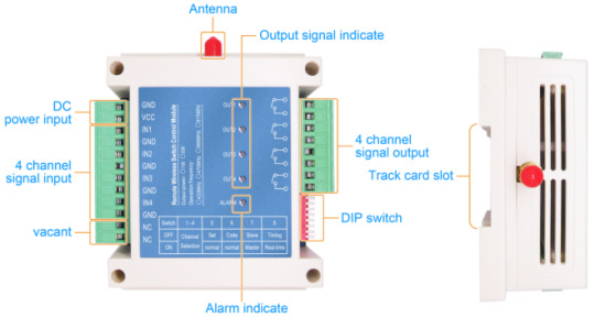
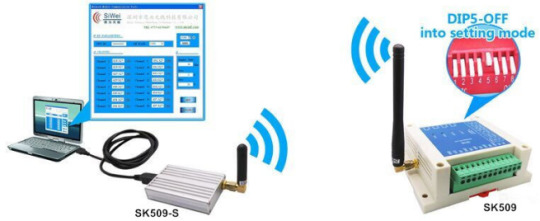
Users can configure and modify the internal parameters of the module wirelessly using a PC interface. The DIP switches on the module can also be used to change the working frequency (16 selectable groups), working mode, and other settings, offering flexible and convenient usage. This article mainly explains the immediate working mode of the SK509 switch control module.
Before explaining the working modes, it is essential to understand the DIP switch definitions of the SK509 switch control module.
The functions of the DIP switch settings are described as follows:
DIP8—communication mode selection
ON – real-time mode ( In this mode, output sync to the input immediately once the input state changed)
OFF - timing mode ( output sync to in the input at set time interval )
DIP7 - master/slave selection
ON - the master
OFF - the slave
DIP6 – time interval selection of timing mode
ON – non pairing mode ( valid when DIP 5 is On )
OFF – pairing mode ( pair the module in this mode , valid when DIP 5 is On )
DIP5 - mode selection
ON - normal working mode
OFF - setting mode ( connect module to PC by SK108-S, set the parameters)
DIP4 ~ 1 - working frequency channel selection, 16 channels in total (default channel interval is 0.5M), frequency can be reset by PC.
Relationship between DIP switches and working frequency channel:

Note:
1.After the user modifies the DIP switch settings, the module needs to be powered off and on again for the changes to take effect.
2.Each time the module is powered on, it will check the status of the DIP switches. If the module detects that the status of DIP7 and DIP8 differs from the previous power-on state, the previously paired channel will be canceled, and the user will need to re-pair the channels.
Real-time working mode
In real time mode, both the master and slaver will send a inquiry signal at set time interval (default time is 3minutes) , the other side , master or slaver will reply the synchronized message. If this communication failed for continuous 3times, the alarm will light on to indicate, the related output will resume to open state;
In real-time mode, if modules never paired before,it is in non paired mode.
Each module has four independent input and four independent output. In real-time mode, the change of any input of the four channels will trigger the transmission, in other side the corresponding relay of the module will be synchronized after got the signal, then it returns a acknowledged signal. If no acknowledged signal come to the triggered modules, the alarm LED will light on. All the output relays will be resumed open if no acknowledge signal received for continuous 3 times inquiry.
Input and output status under normal working mode:
The logic relationship of the module as below:

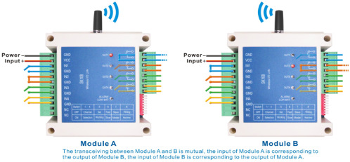
For example, communication between modules A and B,
the 4 output of module A is corresponding to the 4 input of module B,
the 4 output of module B is corresponding to the 4 input of module A, shown as below:
In real time mode,SK509 can work in pairing mode or non pairing mode. SK509 will work at pairing mode if it has been paired with any other SK509. Paired SK509 can only work with other paired SK509. It can’t communicate between paired SK509 and non paired SK509.
For paired SK509, it is 2 way communication, the master can control the slave. Slave can control the master. But slave can’t control the slave and master can’t control the other master.
In pairing mode, the status change of input (master or slave ) will synchronized to the output (paired slave or paired master ).
If SK509 has not been paired with other SK509, or been unpaired, it works in non pairing mode. In non pairing mode, the change of input channel will synchronized to the same output channel in other side.
Application

It is important to note that in this working mode, the modules will first synchronize input and output signals upon initial power-up. Therefore, it is not recommended to power on both the transmitter and receiver simultaneously.
0 notes
Text

Interfacing a 5V Four-Channel Relay Module with an Arduino expands the capabilities of your Arduino projects, allowing you to control high-power devices safely and efficiently.
𝑻𝒐 𝒍𝒆𝒂𝒓𝒏 𝒉𝒐𝒘 𝒕𝒐 𝒊𝒏𝒕𝒆𝒓𝒇𝒂𝒄𝒆 5𝑽 4-𝑪𝒉𝒂𝒏𝒏𝒆𝒍 𝑹𝒆𝒍𝒂𝒚 𝑴𝒐𝒅𝒖𝒍𝒆 𝒘𝒊𝒕𝒉 𝑨𝒓𝒅𝒖𝒊𝒏𝒐 𝒄𝒉𝒆𝒄𝒌𝒐𝒖𝒕 𝒕𝒉𝒊𝒔 𝒃𝒍𝒐𝒈👇
#arduino#arduinouno#arduinoprojects#arduinofun#arduinolove#arduinoindonesia#arduino_uno#arduinorobot#electronics#electronicslovers#electronicengineering#electronicsprojects#microcontroller#diyelectronics#electronicsengineering
0 notes
Text
Embracing Tomorrow's Living: Crabtree Signia Smart Switches Revolutionize Home Automation

Introduction:
In the dynamic realm of smart homes, Crabtree's Signia Smart Switches shine as a symbol of innovation, effortlessly marrying state-of-the-art technology with sophisticated design. If you're yearning to elevate your home into a futuristic haven of convenience, these smart switches open the gateway to a transformation in the way you interact with your living space.
Crabtree Signia Smart Switches: A Quick Glimpse
Crabtree, a stalwart in the electrical fittings industry, takes a leap into the future with its Signia Smart Switches. More than mere additions to your home, these switches mark a transition towards a more intelligent and interconnected living environment.
The Signia Smart Switches lineup includes a diverse range of products tailored to diverse needs:
1. Two Channel Relay Switch:
- A smart two-channel switch featuring high-sensitivity touch keys.
- LED indicators on each button for intuitive control.
- 2-in-1 Feather Touch design for a touch of elegance.
- A versatile 2 Module, 2 Switches configuration for various applications.
- Retrofit Solution for seamless integration.
- Effortless installation with Wi-Fi connectivity (2.4 GHz).
2. Four Channel Relay Switch:
- A smart four-channel switch boasting high-sensitivity touch keys.
- LED indicators for clarity in operation.
- 4-in-1 Feather Touch design for enhanced functionality.
- 2 Module, 4 Switches configuration for comprehensive control.
- Retrofit Solution for easy integration.
- Wi-Fi compatibility (2.4 GHz) for seamless connectivity.
3. 20 A Relay Switch:
- A smart single-channel power switch with high-sensitivity touch keys.
- LED indicator for precise control.
- 1 Feather Touch, 2 Module, 20 Amp Switch for heavy load appliances.
- Retrofit Solution for integration into existing setups.
- Easy installation and Wi-Fi compatibility (2.4 GHz).
4. Curtain Relay Switch:
- A smart Curtain switch with a built-in controller.
- High-sensitivity touch keys for intuitive operation.
- LED indicators on each button.
- 2 Module drape/curtain motor control for tailored curtain movements.
- Retrofit Solution for seamless integration.
- Easy installation and Wi-Fi compatibility (2.4 GHz).
The Future of Home Automation Unveiled
Crabtree Signia Smart Switches usher in an era where homes transcend mere spaces into extensions of our lifestyle. Let's delve into the features that position these smart switches as the vanguard of home automation:
1. Intelligent Control:
- High sensitivity touch keys and LED indicators on each button provide an intelligent and intuitive control experience. No more fumbling for switches in the dark; Signia Smart Switches guide you effortlessly.
2. Versatility in Design:
- With configurations like 2 Module 2 Switches, 2 Module 4 Switches, and 1 Feather Touch 2 Module 20 Amp Switch, Crabtree ensures Signia Smart Switches cater to diverse needs. Control lights, fans, or heavy-load appliances – there's a smart switch for every requirement.
3. Seamless Integration:
- The Retrofit Solution ensures that upgrading your home to a smart ecosystem is a breeze. Signia Smart Switches seamlessly integrate into your existing setup, eliminating the need for extensive rewiring.
4. Easy Installation:
- Prioritizing user convenience, Crabtree Signia Smart Switches offer easy installation that can be done without the need for professional assistance. The simplicity of the process ensures that anyone, regardless of technical expertise, can enjoy the benefits of a smart home.
5. Wi-Fi Connectivity (2.4 GHz):
- Designed to work with Wi-Fi at 2.4 GHz, Signia Smart Switches ensure stable and reliable connectivity. This feature not only facilitates remote control of your home appliances but also opens up possibilities for integration with other smart devices and platforms.
Applications Across Spaces
The versatility of Crabtree Signia Smart Switches extends beyond residential spaces, finding applications in various environments:
1. Residential Spaces:
- Transform your living room, bedroom, kitchen, and more with intelligent lighting and appliance control. Create customized scenarios for different moods and activities.
2. Commercial Establishments:
- Enhance the efficiency of your workspace by integrating Signia Smart Switches. Control lighting, fans, and other devices with a touch, creating an optimal working environment.
3. Hospitality Industry:
- Elevate the guest experience in hotels and resorts with smart lighting and curtain control. The seamless integration of these switches adds a touch of luxury to hospitality spaces.
4. Healthcare Facilities:
- In healthcare settings, where precision and efficiency are crucial, Signia Smart Switches offer a reliable solution for controlling lighting and other electrical appliances.
The Environmental Impact
Beyond immediate benefits, Crabtree Signia Smart Switches contribute to environmental sustainability. Remote control capabilities enable users to optimize energy consumption, reducing unnecessary usage and lowering electricity bills.
The Signia Smart Switches Advantage
Crabtree Signia Smart Switches stand out in the competitive market of smart home devices due to their commitment to quality, innovation, and user-centric design:
1. Trusted Brand:
- Crabtree brings a level of trust and reliability to its smart switches, inheriting its rich legacy in the electrical fittings industry.
2. Innovation in Design:
- The Feather Touch design, LED indicators, and versatile configurations showcase Crabtree's commitment to innovative design that enhances both aesthetics and functionality.
3. Easy Adoption:
- The Retrofit Solution and easy installation process ensure that incorporating Signia Smart Switches into your home doesn’t require a major overhaul. It's a step-by-step transformation that you can control.
4. Customer Support:
- Crabtree's dedication to customer satisfaction extends beyond the purchase, providing responsive customer support for any queries or concerns.
Conclusion: Embrace the Future Today
Crabtree Signia Smart Switches represent more than just a technological upgrade; they signify a lifestyle shift towards a more connected and intelligent future. Transform your home into a haven of convenience, efficiency, and style with these smart switches. Embrace the future today and experience the seamless integration of technology into your daily life. Crabtree Signia Smart Switches are not just switches; they are a gateway to the future of home automation.
0 notes
Text
SMS Remote Monitoring RTU S275 for smart computer room power environment monitoring

Background
Computer rooms exist in all aspects of life, such as in hospitals, schools, enterprises, government agencies, and office buildings.
The general computer room contains key devices such as computer, server, storage equipment, UPS, precision air conditioners, and cabinet groups. When an accident occurs in a traditional computer room, it cannot be discovered and dealt with in time, resulting in a wide range of influence and serious losses.
Safety hazards in the computer room
The danger mainly comes from four hidden dangers:
Electrical safety hazards
Abnormal power supply current, unstable mains power environment, UPS power failure, high cable temperature, etc.
Potential safety hazards
Lax access to the computer room, information leakage, human and material resources spent on computer room monitoring, lines being removed, reconnected or destroyed, etc.
Abnormal environmental hazards
The ambient temperature exceeds the bearing temperature of the equipment, causing open fire accidents, environmental liquid leakage %2F water leakage, circuit short circuit, and abnormal air humidity causing safety hazards, etc.
Hidden dangers of alarm delay
lack of early warning in the room, it is difficult to control abnormalities in real time, the inspection frequency of ordinary computer rooms is low, problems are difficult to find, and human supervision is difficult to detect abnormalities in time, etc.
Program overview
Data acquisition gateway S275 provides 4 channels of digital input, 2 channels of relay output and 1 channel of temperature and humidity input, and provides one RS485 serial port at the same time, which can be expanded to 320 digital inputs, digital outputs, analog data acquisition and instrument data reading Write. The S275 is connected to the DAM expansion module through RS485 to collect data such as temperature, humidity, water leakage, infrared, smog, current, voltage, power failure, UPS, etc. in the computer room, and conduct real-time monitoring and centralized control of the power equipment in the computer room to fully ensure the safety and stability of the power system in the computer room. Once the monitoring data exceeds the safe range, the system will immediately notify the user through SMS, dial a phone, GPRS, 3G, 4G network and transmit data to the monitoring center, mobile APP, WEB monitoring center and can control air conditioners and fans according to user needs. The computer room creates a safe and worry-free operation and maintenance environment.
More information view: https://www.bliiot.com/m2m-rtu-p00175p1.html
0 notes
Text
Channel Relay Module: Everything you need to know
The 4 Channel Relay Module controls high-voltage, high-current load such as motor, solenoid valves, power lamps, and AC load. The 4 Channel Relay Module comprises four 5V relays and the associated switching and isolating components, making the interfacing with a microcontroller or sensor easy with minimum features and connections.
Relay modules can be used across industries, including process technology and power engineering, railway applications, machine engineering, and general control cabinet construction.
Technical Data
• Number of digital outputs: 4 • Total number of channels (module): 4 • Actuator connection: 4 x (1-wire) • Output circuit design: 4 make contacts Relay • Output characteristic: potential-free • Switching frequency (max.): 0.33 Hz; 3 A / 250 VAC, 30 VDC • Switching frequency (max.) (2): 0.1 Hz; 5 A / 250 VAC, 30 VDC • Load type of switching frequency: 3 A / 250 VAC, 30 VDC • Switching voltage (max.): 250 VAC; 30 VDC; 110 VDC at 0.4 A • Switching current (max.): 2A • Switching current (note): 5 A for single-channel use • Switching power: 1250 VA / 150 W; cos ϕ max. = 0.4; L/R max. = 7 ms • Pull-in time (max.): 10ms • Drop-out time (max.): 5ms • Bounce time (typ.): 1ms • Electrical switching operations (min.) (at max. resistive load): 100 x 10³ switching operations • Mechanical switching operations (min.) (at max. resistive load): 20 x 10⁶ switching operations • Output data width (internal) max.: 4bits • Supply voltage (system): 5 VDC; via data contacts • Current consumption (5 V system supply) 95mA • Isolation: 1500 V (system/field) • Indicators: LED (A-D) green: Status relay 1 … relay 4
Features
• Input supply 12 VDC @ 170 mA • Output four SPDT relay • Relay specification 5 A @ 230 VAC • Trigger level 2 ~ 5 VDC • Berg pins for connecting power and triggering voltage • LED on each channel indicates relay status • Power Battery Terminal (PBT) for accessible relay output and aux power connection • Four mounting holes of 3.2 mm each • PCB dimensions 88 mm x 68 mm
Four-Channel Relay Module Usage
The most significant advantage of the 4 Channel Relay Module is that it can switch multiple loads at the same time due to four relays present on the same module. This type of relay module provides the perfect solution for home automation. It can be placed in the main switchboard, connected to loads in other parts of the house, and controlled from a central location using a microcontroller.
Benefits of Relay Modules
• Electromagnetic relays have a fast process and speedy reset • They can be operated for both AC and DC systems for the safety of AC and DC equipment • Electromagnetic relays operate at speeds that can manage in milliseconds and are also possible • Relay Modules are simple, robust, compact, and reliable • These relays are almost instantaneous. Though quick, the operating time of the relay varies with the current. With different setups like dashpot, copper rings, etc., slow operational duration and reset can be possible.
How does it work?
This relay module has three high voltage terminals (Normally Closed (NC), Common terminal (C), and Normally Open (NO)) that attach to the device you want to handle. The other side has three low voltage pins (Ground, Vcc, and Signal) that join Arduino.
0 notes
Video
youtube
Interface ESP8266-01 Wi-Fi Module with Raspberry Pi Pico
#youtube#Interface ESP8266-01 Wi-Fi Module with Raspberry Pi Pico & 4 Channel Relay Control Home Automation📱 https://www.youtube.com/watch?v=yTsKyPg
0 notes
Link
Switches have the power to change the aesthetics of residential or commercial space. It is a segment with a varied price range from Rs 12 to Rs 800 per piece. Schneider provides the best electric switches for a home in India, in the most affordable range. They are made with innovative and robust designs to meet the various requirements with the best deliverance.
1 note
·
View note
Text
Relay Module for Raspberry Pi | 4 Channel 3V Relay Board for Raspberry Pi
Raspberry pi 4 Channel 3V Relay Board
4 channel relay shield with 2A 120 Volts AC output and 2A 24 Volts DC output ratings. 4 High-quality 3V Relays that loads up to 2A/24VDC or 2A/120VAC. Compatible with all models of the Raspberry Pi such as Raspberry Pi 4, 3, 2, Zero and Zero W. @raspberrypigk @raspberrypi-piface @electronics-geek
#Raspberry pi#Relay Module#Relay Board#Relay Board for Raspberry Pi#4 channel relay board#3v Relay Board for Raspberry Pi
0 notes