#microcontroller based automatic gate control
Explore tagged Tumblr posts
Visit Tumblr Blog
Explore Tumblr blogs with no restrictions, modern design and the best experience.
Last Seen Tumblr Blogs


Fun Fact
The Tumblr office adopted Tommy, an 11-year-old Pomeranian.
Text
Demystifying the Thyristor Rectifier: Power Conversion at Its Most Intelligent
Have you ever stopped to think about how your high-powered industrial machines, metro rails, or even complex DC motors get their power regulated? Behind the quiet hum of a production floor or the seamless acceleration of an electric train lies a sophisticated system—meticulously designed to control, convert, and deliver power with surgical precision. At the heart of many of these systems is something often overlooked but absolutely essential: the thyristor rectifier.
Though it may sound like something straight out of a textbook, the thyristor rectifier is very much a workhorse of modern industry—a silent guardian in countless high-power applications. Let’s explore what it does, how it works, and why it continues to be a staple in high-voltage environments, even in an age of rapid technological change.
What Is a Thyristor Rectifier?
To put it simply, a thyristor rectifier is a type of power converter that uses thyristors (semiconductor devices also known as silicon-controlled rectifiers, or SCRs) to convert alternating current (AC) into direct current (DC). Unlike traditional diode rectifiers that passively convert AC to DC, a thyristor rectifier allows for active control over voltage and current.
Think of it like the difference between a basic faucet and a smart water mixer. One just opens and closes; the other gives you full control over pressure, temperature, and flow rate. That’s the leap from diodes to thyristors.
The Human Side of Power Conversion
Take Satish, a power systems engineer in Hyderabad who’s been designing rectifier panels for over two decades. “You don’t usually hear people say they’re passionate about rectifiers,” he chuckles. “But these little guys are responsible for ensuring the safety and precision of entire production lines. That’s not something to overlook.”
Satish remembers working on a thyristor rectifier system for a steel plant where consistency in DC current was critical. “We had to ensure zero fluctuations, otherwise the rolling mills would produce defects. That’s how critical precise conversion becomes.”
The Anatomy of a Thyristor Rectifier
1. Thyristors (SCRs)
These are the core switching devices. A thyristor can handle extremely high voltages and currents—perfect for industrial-scale applications.
2. Gate Control
Unlike diodes that pass current as soon as a voltage is applied, thyristors require a gate signal to start conduction. This is what allows for control—engineers can determine exactly when the current flows.
3. Feedback and Monitoring Systems
Most modern rectifiers are equipped with sensors and microcontrollers that monitor load conditions, automatically adjusting the gate signals to optimize performance.
Use Cases Where They Shine
- Metallurgy and Electroplating
These industries require high-current DC power with minimal ripple. A thyristor rectifier provides just that—with adjustable output and exceptional stability.
- Traction Systems
Railways and trams rely on reliable DC power to move entire fleets. Thyristor-based systems have been the go-to solution for decades.
- DC Motor Drives
Industrial processes from conveyor belts to mixers need dynamic torque and speed control. Thyristor rectifiers allow motors to be ramped up or down with surgical accuracy.
The Benefits You Might Not See—but Should Appreciate
✅ Energy Efficiency
They offer higher power factor correction and reduced harmonics compared to older systems.
✅ Robustness
Thyristors are inherently rugged—they can survive overloads, voltage surges, and harsh environments with minimal failure.
✅ Long Lifecycle
Because there are fewer moving parts and the components are solid-state, these systems often last for decades with basic maintenance.
Real-World Challenges and Smart Engineering
Despite their advantages, thyristor rectifiers aren't without challenges. They can introduce harmonics into the power supply, require complex cooling systems, and sometimes fall short in rapid dynamic responses compared to modern IGBT-based solutions.
This is where clever engineering comes in. For instance, engineers like Maria from São Paulo are implementing hybrid systems—combining thyristors with active filters or digital signal processors to mitigate harmonics and improve real-time control.
“It’s all about understanding where the technology fits best,” she explains. “There’s no one-size-fits-all in power engineering.”
How They Compare to Modern Alternatives
- Versus Diode Rectifiers
Thyristor rectifiers offer control, while diodes don’t. That alone makes them superior in complex systems where variability matters.
- Versus IGBT-based Inverters
IGBTs (Insulated Gate Bipolar Transistors) offer faster switching and better performance at lower voltages. But for high-power, high-voltage industrial use? Thyristors still rule the game.
What’s the Future for Thyristor Rectifiers?
As the world shifts toward automation, electric transportation, and renewable energy, thyristor rectifiers are also evolving. Here’s what to expect:
Digital Integration: With the advent of smart factories (Industry 4.0), thyristor rectifiers are being integrated with PLCs, SCADA systems, and IoT dashboards for real-time diagnostics and remote management.
Modular Design: New systems are adopting modular builds, making them easier to scale, maintain, and upgrade.
Sustainability Focus: With energy efficiency becoming a compliance requirement, future rectifier systems will prioritize low losses and high thermal efficiency.
A Story That Resonates
Sometimes it’s easy to think of components like rectifiers as just “hardware.” But they are crucial enablers—ensuring that critical infrastructure keeps running 24/7, from hospitals to airports, from data centers to disaster relief efforts.
“I once worked on a power backup system for a metro line,” shares Arun, an electrical contractor in Delhi. “There was a major grid failure one monsoon night, but the system held up. That rectifier didn’t blink. Imagine the chaos if it had.”
It’s in those moments—the moments that go unnoticed—that a well-designed thyristor rectifier proves its worth.
Final Thoughts: Unsung Heroes of Modern Industry
While they might not be flashy or as celebrated as AI or blockchain, thyristor rectifiers are the backbone of industrial energy systems. They combine decades of engineering wisdom with the evolving needs of the 21st-century power grid.
In an era where we’re rushing to reinvent everything, sometimes it’s the enduring technologies—the ones that quietly evolve with us—that deserve the spotlight.
So the next time you see a conveyor belt moving seamlessly, or a rail system gliding past, remember—there’s likely a thyristor rectifier working behind the scenes, doing its job without complaint.
0 notes
Video
youtube
GSM - SMS Based Railway Crossing Gate Control Through Arduino | Automatic Railway Gate Control System Using Android | Railway Level Crossing Gate Control through GSM by SMS with User Programmable Number Features by the Station Master or the Driver | Railway Gate Control Through Arduino Alerts via GSM - SMS | SMS CONTROLLED RAILWAY LEVEL GATE USING ARDUINO | automatic railway gate control system using arduino | PPT | Automatic Railway Gate Control using Audrino | Automated Level Crossing with Alert System and GSM.***********************************************************If You Want To Purchase the Full Working Project KITMail Us: [email protected] Name Along With You-Tube Video LinkWe are Located at Telangana, Hyderabad, Boduppal. Project Changes also Made according to Student Requirementshttp://svsembedded.com/ https://www.svskits.in/ http://svsembedded.in/ http://www.svskit.com/M1: 91 9491535690 M2: 91 7842358459 We Will Send Working Model Project KIT through DTDC / DHL / Blue Dart / First Flight Courier ServiceWe Will Provide Project Soft Data through Google Drive1. Project Abstract / Synopsis 2. Project Related Datasheets of Each Component3. Project Sample Report / Documentation4. Project Kit Circuit / Schematic Diagram 5. Project Kit Working Software Code6. Project Related Software Compilers7. Project Related Sample PPT’s8. Project Kit Photos9. Project Kit Working Video linksLatest Projects with Year Wise YouTube video Links157 Projects https://svsembedded.com/ieee_2022.php135 Projects https://svsembedded.com/ieee_2021.php 151 Projects https://svsembedded.com/ieee_2020.php103 Projects https://svsembedded.com/ieee_2019.php61 Projects https://svsembedded.com/ieee_2018.php171 Projects https://svsembedded.com/ieee_2017.php170 Projects https://svsembedded.com/ieee_2016.php67 Projects https://svsembedded.com/ieee_2015.php55 Projects https://svsembedded.com/ieee_2014.php43 Projects https://svsembedded.com/ieee_2013.php1100 Projects https://www.svskit.com/2022/02/900-pr...***********************************************************1. Automatic Railway Gate Control System Alert via SMS,2. advantages of automatic railway gate control system,3. Alarm System of Railway Gate Crossing based on GPS and GSM,4. applications of automatic railway gate control system,5. Arduino crossing gate controller,6. Arduino train crossing,7. Automated Railway Crossing With Auto Train Speed Control Technology and Live Tracking.,8. Automatic Rail crossing Barrier,9. AUTOMATIC RAIL GATE CONTROL WITH GSM ,RFID BY VELTECH MULTITECH STUDENTS,10. automatic railway barrier,11. Automatic railway gate,12. Automatic railway gate control,13. automatic railway gate control documentation,14. automatic railway gate control pdf,15. automatic railway gate control ppt,16. automatic railway gate control project price,17. automatic railway gate control project report,18. automatic railway gate control seminar report,19. Automatic Railway Gate Control System GSM Based Railway Track Fault Detection,20. automatic railway gate control system project report pdf,21. automatic railway gate control system research paper,22. automatic railway gate control system using 8051 microcontroller ppt,23. automatic railway gate control system using microcontroller,24. automatic railway gate control system using ultrasonic sensor,25. automatic railway gate control system with signals,26. automatic railway gate control using 8051 microcontroller code,27. automatic railway gate control using 8051 microcontroller report,28. automatic railway gate control using Arduino,29. automatic railway gate control using arduino and ultrasonic sensor,30. automatic railway gate control using arduino ppt,31. automatic railway gate control using arduino ppt download,32. automatic railway gate control using arduino project report pdf,33. automatic railway gate control using iot,34. automatic railway gate control using ir sensor,35. automatic railway gate control using microcontroller,36. Automatic railway gate control.,37. automatic railway gate controller using 8051,38. automatic railway gate controller with high speed alerting system pdf,39. Automatic railway gate crossing | KIET GHAZIABAD,40. block diagram of automatic railway gate control system,41. conclusion of automatic railway gate control system,42. Controlling of Railway Level Crossing Gate through GSM Using Programmable Number Features,43. disadvantages of automatic railway gate control system,44. future scope of automatic railway gate control system,45. GSM automatic railway gate,46. gsm based railway gate control and track switching,47. how railway gate works,48. intelligent railway station monitoring and alert system,49. introduction of automatic railway gate control system,
0 notes
Text
PROJECT TOPIC- CONSTRUCTION OF A MICROCONTROLLER BASED GATE
PROJECT TOPIC- CONSTRUCTION OF A MICROCONTROLLER BASED GATE
PROJECT TOPIC- CONSTRUCTION OF A MICROCONTROLLER BASED GATE ABSTRACT
Microcontroller based automate controller is a project design of a system that is used in operating a gate automatically. The system opens the gate automatically when a human being or car is about to enter a compound or exit a compound. The system works by sensing the light rays from the head lamp of the vehicle. The light…
View On WordPress
#microcontroller based automatic gate control#microcontroller based automatic railway gate control circuit diagram#microcontroller based automatic railway gate control project report#microcontroller based automatic railway gate control system abstract#microcontroller based automatic railway gate control system circuit diagram#microcontroller based automatic railway gate control system pdf#microcontroller based automatic railway gate control system project#microcontroller based automatic railway gate control system report#microcontroller based dam gate control system
0 notes
Text
Real-time Embedded Systems Projects
In embedded systems, software commonly known as firmware is hidden inside the same hardware rather than in some other hardware. Basically Real Time embedded systems Projects are task specific devices. One of its most important characteristic is gives the output within the time constraints or you can say they are time bound systems.
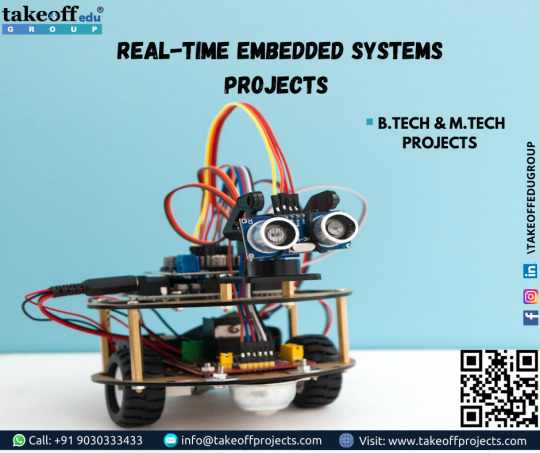
These embedded systems help to make the work more convenient and accurate. So, we often use these embedded systems in simple and complicated devices too. We use these embedded systems in our real life for many devices and applications such as Calculators, microwave, television remote control, home security and neighborhood traffic control systems, etc.
Many engineering students show lot of interest to do the projects based on real time embedded systems projects in their final year. For their purpose, we have listed here some of the best Real Time embedded systems projects ideas which are all very helpful to get an idea about what type of projects that they can choose in engineering level.
This list includes many 8051 Microcontroller Projects, PIC Projects and AVR Microcontroller projects. Some of the examples of microcontroller based projects are water level controller using 8051, Propeller LED display, Automatic Railway Gate Controller with High Speed Alerting System, Metal detector robot, Biometric attendance system, etc.
0 notes
Video
youtube
How to Control Room Light Automatically using Arduino | Home Automation using Arduino
Often we see visitor counters at stadium, mall, offices, class rooms etc. How they count the people and turn ON or OFF the light when nobody is inside? Today we are here with automatic room light controller project with bidirectional visitor counter by using Arduino Uno. It is very interesting project for hobbyists and students for fun as well as learning.
The project of “Digital visitor counter” is based on the interfacing of some components such as sensors, motors etc. with arduino microcontroller. This counter can count people in both directions. This circuit can be used to count the number of persons entering a hall/mall/home/office in the entrance gate and it can count the number of persons leaving the hall by decrementing the count at same gate or exit gate and it depends upon sensor placement in mall/hall. It can also be used at gates of parking areas and other public places.
0 notes
Text
Channel Mosfet

MOSFET Tizen deezer 2.
N Channel Mosfet Circuit
P Channel Mosfet Operation
N Channel Mosfet Symbol
ST's P-channel MOSFET portfolio is optimized to meet a broad range of requirements for load switch, linear regulator, automotive applications and specifically designed for portable applications. The MOSFET is another category of field-effect transistor.There are two types of MOSFET, Enhancement mode MOSFET and Depletion mode MOSFET. Major Brands BS250 N-Channel MOSFET Transistor, TO-92, 3 Pin, 5.2 mm H x 4.2 mm W x 4.8 mm L (Pack of 10) 5 $8 79 ($0.88/Transistor). This Article Shows A Detailed And Clear Explanation Of MOSFET Working, Structure, Analysis, Example, Applications, Benefits And Many Others. If you need to switch high current and or high voltage loads with a micro controller you'll need to use some type of transistor. I'm going to be covering how to use a MOSFET since it's a better.
The MOSFET is an important element in embedded system design which is used to control the loads as per the requirement. Many of electronic projects developed using MOSFET such as light intensity control, motor control and max generator applications. The MOSFET is a high voltage controlling device provides some key features for circuit designers in terms of their overall performance. This article provides information about different types of MOSFET applications.
MOSFET and Its Applications
The MOSFET (Metal Oxide Semiconductor Field Effect Transistor) transistor is a semiconductor device which is widely used for switching and amplifying electronic signals in the electronic devices.The MOSFET is a three terminal device such as source, gate, and drain. The MOSFET is very far the most common transistor and can be used in both analog and digital ckt.
The MOSFET works by varying the width of a channel along which charge carriers flow (holes and electrons). The charge carriers enter the channel from the source and exits through the drain. The channel width is controlled by the voltage on an electrode is called gate which is located between the source and drain. It is insulated from the channel near an extremely thin layer of metal oxide. There is a different type of MOSFET applications which is used as per the requirement.
Types of MOSFET Devices
The MOSFET is classified into two types such as;
Depletion mode MOSFET
Enhancement mode MOSFET
Depletion Mode: When there is zero voltage on the gate terminal, the channel shows its maximum conductance. As the voltage on the gate is negative or positive, then decreases the channel conductivity.
Depletion Mode MOSFET
Enhancement Mode
When there is no voltage on the gate terminal the device does not conduct. Twitch deezer. More voltage applied on the gate terminal, the device has good conductivity.
Enhance Mode MOSFET
MOSFET Working Principle
The working of MOSFET depends upon the metal oxide capacitor (MOS) that is the main part of the MOSFET. The oxide layer presents among the source and drain terminal. It can be set from p-type to n-type by applying positive or negative gate voltages respectively. When apply the positive gate voltage the holes present under the oxide layer with a repulsive force and holes are pushed downward through the substrate. The deflection region populated by the bound negative charges which are allied with the acceptor atoms.
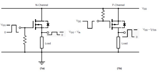
P- Channel MOSFET
The P-Channel MOSFET consist negative ions so it works with negative voltages. When we apply the negative voltage to gate, the electrons present under the oxide layer through pushed downward into the substrate with a repulsive force. The deflection region populates by the bound positive charges which are allied with the donor atoms. The negative voltage also attracts holes from p+ source and drain region into the channel region.

P-Channel MOSFET
N- Channel MOSFET
When we apply the positive gate voltage the holes present under the oxide layer pushed downward into the substrate with a repulsive force. The deflection region is populated by the bound negative charges which are allied with the acceptor atoms. The positive voltage also attracts electrons from the n+ source and drain regions into the channel. Now, if a voltage is applied among the drain and source the current flows freely between the source and drain and the gate voltage controls the electrons in the channel. In place of positive voltage if we apply a negative voltage (hole) channel will be formed under the oxide layer.
N-Channel MOSFET
MOSFET Applications
The applications of the MOSFET used in various electrical and electronic projects which are designed by using various electrical and electronic components. For better understanding of this concept, here we have explained some projects.
MOSFET Used as a Switch
In this circuit, using enhanced mode, a N-channel MOSFET is being used to switch the lamp for ON and OFF. The positive voltage is applied at the gate of the MOSFET and the lamp is ON (VGS =+v) or at the zero voltage level the device turns off (VGS=0). If the resistive load of the lamp was to be replaced by an inductive load and connected to the relay or diode to protect the load. In the above circuit, it is a very simple circuit for switching a resistive load such as LEDs or lamp. But when using MOSFET to switch either inductive load or capacitive load protection is required to contain the MOSFET applications. If we are not giving the protection, then the MOSFET will be damaged. For the MOSFET to operate as an analog switching device, that needs to be switched between its cutoff region where VGS =0 and saturation region where VGS =+v.
Auto Intensity Control of Street Lights using MOSFET
Now-a-days most of lights placed on the highways are done through High Intensity Discharge lamps (HID), whose energy consumption is high. Its intensity cannot be controlled according to the requirement, so there is a need to switch on to an alternative method of lighting system, i.e., to use LEDs. This system is built to overcome the present day drawbacks of HID lamps.
Auto Intensity Control of Street Lights using MOSFET
This project is designed to control the lights automatically on the highways using microprocessor by variants of the clock pulses. In this project, MOSFET plays major role that is used to switch the lamps as per the requirement. The proposed system using a Raspberry Pi board that is a new development board consist a processor to control it. Here we can replace the LEDs in place of HID lamps which are connected to the processor with the help of the MOSFET. The microcontroller release the respective duty cycles, then switch the MOSFET to illuminate the light with bright intensity
Marx Generator Based High Voltage Using MOSFETs
The main concept of this project is to develop a circuit that delivers the output approximately triple to that of the input voltage by Marx generator principle. It is designed to generate high-voltage pulses using a number of capacitors in parallel to charge during the on time, and then connected in series to develop a higher voltage during the off period. If the input voltage applied is around 12v volts DC, then the output voltage is around 36 volts DC.
This system utilizes a 555 timer in astable mode, which delivers the clock pulses to charge the parallel capacitors during on time and the capacitors are brought in a series during the off time through MOSFET switches; and thus, develops a voltage approximately triple to the input voltage but little less, instead of exact 36v due to the voltage drop in the circuit. The output voltage can be measured with the help of the multimeter.
EEPROM based Preset Speed Control of BLDC Motor
The speed control of the BLDC motor is very essential in industries as it is important for many applications such as drilling, spinning and elevator systems. This project is enhanced to control the speed of the BLDC motor by varying the duty cycle.
EEPROM based Preset Speed Control of BLDC Motor
The main intention of this project is to operate a BLDC motor at a particular speed with a predefined voltage . Therefore, the motor remains in an operational state or restarted to operate at the same speed as before by using stored data from an EEPROM.
Before using Praat to do sound analysis, we have to be clear about know that what information we can get from Praat. Table 1 presents some major acoustic variables we usually use to analyze the speech sounds. 49) for visual presentation of the variables. Praat is a free software package used for speech analysis in phonetics. It is designed and continuously developed by Paul Boersma and David Weenink of the University of Amsterdam. It is a flexible tool that offers a broad range of standard and non-standard procedures such as spectrographic analysis, speech synthesis, articulatory synthesis and neural networks. Praat allows you to divide up the sound signal into temporal stretches or intervals, and to assign text or labels to these intervals. It does this by means of what it calls a TextGrid. The basic idea is that one might want to divide a signal into intervals in more than one way. Praat scripts Phonetics Laboratory Scripts and batch processes are a handy way of saving time while performing repetitive operations. In this page we share some of the Praat scripts we use in our Lab. All the scripts include instructions (either at the begining of the file or in the first form of the script). PRAAT is a very flexible tool to do speech analysis. It offers a wide range of standard and non-standard procedures, including spectrographic analysis, articulatory synthesis, and neural networks. This tutorial specifically targets clinicians in the field of communication disorders who want to learn more about the use of PRAAT as part of an. Praat phonetics.
The speed control of the DC motor is achieved by varying the duty cycles (PWM Pulses) from the microcontroller as per the program. The microcontroller receives the percentage of duty cycles stored in the EEPROM from inbuilt switch commands and delivers the desired output to switch the driver IC in order to control the speed of the DC motor. If the power supply is interrupted, the EEPROM retains that information to operate the motor at the same speed as before while the power supply was available.
LDR Based Power Saver for Intensity Controlled Street Light
In the present system, mostly the lightning-up of highways is done through High Intensity Discharge lamps (HID), whose energy consumption is high and there is no specialized mechanism to turn on the Highway light in the evening and switch off in the morning. Recoverit download mac.
LDR Based Power Saver for Intensity Controlled Street Light
N Channel Mosfet Circuit

P Channel Mosfet Operation
Its intensity cannot be controlled according to the requirement, so there is a need to switch to an alternative method of lighting system, i.e., by using LEDs. This system is built to overcome the present day, drawback of HID lamps.
This system demonstrates the usage of LEDs (light emitting diodes) as light source and its variable intensity control, according to the requirement. LEDs consume less power and its life is more, as compared to conventional HID lamps.
The most important and interesting feature is its intensity that can be controlled according to requirement during non-peak hours, which is not feasible in HID lamps. A light sensing device LDR (Light Dependent Resistance) is used to sense the light. Its resistance reduces drastically according to the daylight, which forms as an input signal to the controller . A cluster of LEDs is used to form a street light. The microcontroller contains programmable instructions that controls the intensity of lights based on the PWM (Pulse width modulation) signals generated.
The intensity of light is kept high during the peak hours, and as the traffic on the roads tend to decrease in late nights; the intensity also decreases progressively till morning. Finally the lights get completely shut down at morning 6 am, to resume again at 6pm in the evening. The process thus repeats.
SVPWM (Space Vector Pulse Width Modulation)
The Space Vector PWM is a sophisticated technique for controlling AC motors by generating a fundamental sine wave that provides a pure voltage to the motor with lower total harmonic distortion. This method overcomes the old technique SPWM to control an AC motor that has high-harmonic distortion due to the asymmetrical nature of the PWM switching characteristics.
In this system, DC supply is produced from the single-phase AC after rectification, and then is fed to the 3-phase inverter with 6 numbers of MOSFETs. For each phase, a pair of MOSFETare used, and, therefore, three pairs of MOSFETs are switched at certain intervals of time for producing three-phase supply to control the speed of the motor. This circuit also gives light indication of any fault that occurs in the control circuit
N Channel Mosfet Symbol
Therefore, this is all about types of MOSFET applications, Finally, we will conclude that, the MOSFET requires high voltage whereas transistor requires low voltage and current. As compared to a BJT, the driving requirement for the MOSFET is much better.Furthermore, any queries regarding this article you can comment us by commenting in the comment section below.
0 notes
Text
Embedded projects Takeoff Projects helps students complete their academic projects. You can enrol with friends and receive embedded projects kits at your doorstep. You can learn from experts, build latest projects, showcase your project to the world and grab the best jobs. Get started today! An embedded system is nothing but a computing system which is meant to perform many operations like to access the info , process the info , store the info and also control the info in electronics based systems. In embedded systems, software commonly referred to as firmware is hidden inside an equivalent hardware instead of in another hardware. Basically embedded systems are task specific devices. one among its most vital characteristic is gives the output within the time constraints otherwise you can say they're time bound systems. These embedded systems help to form the work more convenient and accurate. So, we frequently use these embedded systems in simple and sophisticated devices too. We use these embedded systems in our real world for several devices and applications like Calculators, microwave, television remote , home security and neighborhood control systems, etc. Many engineering students show lot of interest to try to to the projects supported embedded systems in their final year. for his or her purpose, we've listed here a number of the simplest embedded systems projects ideas which are all very helpful to urge a thought about what sort of projects that they will choose in engineering level. This list includes many 8051 Microcontroller Projects, PIC Projects and AVR Microcontroller projects. a number of the samples of microcontroller based projects are water level controller using 8051, Propeller LED display, Automatic Railway Gate Controller with High Speed Alerting System, detector robot, Biometric attendance system, etc.
0 notes
Photo

Four IR Sensor Based Automatic Control of Railway Gate using Microcontroller
by Hay Man Oo | Ni Ni San Hlaing | Thin Thin Oo ""Four IR Sensor Based Automatic Control of Railway Gate using Microcontroller""
Published in International Journal of Trend in Scientific Research and Development (ijtsrd), ISSN: 2456-6470, Volume-3 | Issue-5 , August 2019,
URL: https://www.ijtsrd.com/papers/ijtsrd26634.pdf
Paper URL: https://www.ijtsrd.com/engineering/electronics-and-communication-engineering/26634/four-ir-sensor-based-automatic-control-of-railway-gate-using-microcontroller/hay-man-oo
paper publication in science, call for paper medical science, ugc approved management journal
This paper investigates based on four IR sensor automatic control of railway gate using a microcontroller system. There are so many railway accidents happening due to the carelessness in manual operations or lack of worker. So, this paper describes four IR sensor based automatic control of railway gate system for saving precious human lives and preventing major disasters in railway track. Railway gate may be saved for the road users to prevent accidents in terms of train speed at a level crossing. Automatic railway gate control system is an innovative circuit which automatically controls the operation of railway gates detecting the arrival and departure of train at the gate. This automatic system can be replaced by the gates operated by the gatekeeper. The operation using Arduino UNO that integrated with other circuits involved such as power supply, IR sensors, light indicators, buzzer, and gate motors. The servo motor is used to control the open and close status of the railway crossing gate. The four IR sensors are placed on the railway tracks. The gate is closed when the first one senses the train and is opened when the second one senses the train. This operation is performed when the train is coming from the left side of the gate. When the train is coming from the right side, the third and fourth sensors is performed in the same operation. The red LED is HIGH when the gate is closed and the green LED is HIGH when the gate is opened. This system is based on software programming to operate the hardware structure. Program for four IR sensor based automatic control of railway gate system is based on Arduino UNO with C language. The main function of the design is Arduino UNO.
0 notes
Text
[Udemy] Mastering Arduino From beginners To Core Advance
complete guide to arduino,sensors and a lot more with theory and practical What Will I Learn? The students will get a complete theoritical as well as practical knowledge of microcontrollers they will get knowledge of industrial environments IDEs they will get knowledge of sensors and type of motors they will get a complee practical project knowledge and how to deelop it into realtime environment they will get a basic idea of what is a micro controller and how to run motor and sensors with PC Requirements • If you only wish to only view the course ,then nothing is required• If you only wish to only view the course ,then nothing is required • Computer with windows installed • An Arduino or clone board for practical • Complete list of material will be provided in lesson 1 beginning Description "I want to put a ding in the universe." - Steve Jobs Description This course is designed to keep the beginners in mind. The course will provide you with vast theoretical knowledge and practical examples of each part .there is no need to have any prior knowledge in C++ or electronics but if you have then it is a plus point. The course will deal with a large number of topics from basics to watchdog timers to I2C communication method the Arduino framework as well as how to build simple circuits that flash lights and spin motors. Following that, we continue our adventure into making noise, sensing the environment, and building a robot. We will begin our journey by basic knowledge of arduino and micro controllers Then we will go on basic setup processes and connections, after that we will on to running a lot of different motors. After that the sensors details and high level communication. Then the advanced topics with complete knowledge and at the end we will be going to do a complete project with the help of all the things we studied in a real time project. Each video lecture is designed to give you one building block of knowledge. Almost every lecture is followed by a hands-on exercise where I ask you to expand on that building block or combine several previous blocks. I provide solutions to each exercise to help you learn. Additionally, most of the sections contain a project that challenges you to synthesize many of the concepts found in that section and from previous sections. Upon completing this course, you will have the skills and knowledge needed to create fun and useful Arduino projects. The course is broken up into a Simple Projects section, an Intermediate Projects section and an Advanced Projects section allowing you to progress to or start from any level based on how comfortable you are with Arduino. Course overview A lot is there to study and we will begin with the basics to beginners then we will move towards intermediate and then to advance levels. A glimpse of the course is as follows:- 1. Introduction 2. what is arduino 3. microcontroller 4. Atmega 328 details 5. connection of Atmel 328 with arduino 6. arduino UNO and bread board wiring 7. let’s get started with programming 8. download and install software 9. about the environment 10. how to blink led (hello world) 11. arduino syntax 12. understanding variables 13. digital read and serial port 14. analog read 15. introduction to pwm 16. fade a led 17. if conditional statement 18. for loop 19. while loop 20. using array 21. difference between input and output 22. difference between digital and analog 23. multiple led 24. button input 25. analog input 26. analog output 27. liquid crystal display 28. types of motors 29. simple dc motor 30. servo motor 31. stepper motor 32. running dc motor 33. running servo motor 34. running stepper motor 35. introduction to sensors 36. types of sensors potentiometer 37. piezoelectric sensor 38. temperature sensor 39. PIR sensor 40. serial communication 41. serial begin details 42. serial write 43. serial read 44. other IDE for programming 45. Atmel studio 46. wiring ide 47. i2c communication and processing 48. spi interface 49. wireless communication using RF remote 50. RFID card reading 51. watchdog timer 52. automatic gate opener : a real time project 53. using multiple sensors 54. multiple sensor programming 55. using them simultaneously 56. running relay with rf remote 57. running them with RFID card 58. conclusion what you will get • each course video • course complete PDF version to download • complete Codes to download and github link �� full explanations at any time by answering questions Who is the target audience? a wide range of peoples from absolute beginners to hobbyists to expert level intellects source https://ttorial.com/mastering-arduino-beginners-core-advance
0 notes
Text
Smart Door Lock with Facial Recognition system
Super Secure Door Lock System for Critical Zones
Meera Mathew, and R S Divya
23 October 2017
“Security is a defense against threats which provides an assurance of safety. Now and before security is one of the major concern in places like home, offices, institutions, laboratories etc. in order to keep our data confidentially so that no other unauthorized person could have access on them.”
Security plays an important role in our lives. As technology grows day by day, many different kinds of electronic locks were introduced to the people to protect their homes. I find this research relevant to my study because it mainly discuss how electronic locks works and what are the technologies that has been used in automated door locking systems.
A Smart Lock System using Wi-Fi Security
Abdallah kassem, Sami El Murr, Georges Jamous, Ellie Saad, and Marybelle Geaga
5 September 2016
“In large apartment complexes, fraternities, or even for an owner having many keys for each and every apartment, car, or gate he owns, maintaining entry to authorized personnel only is a problem. Besides the costs involved in fabrication, duplication, and distribution of keys, there are security problems in case of lost keys.”
Entrusting your keys to an authorized personnel is too risky nowadays, because of loyalty issues among people. This research is very relevant to my study because, a wide range of applicability will be applied for the users to operate the system remotely. And it discusses about the smart-lock-system that is a complete reinvention of the standard key-door lock, where all the digital keys are stored in a digital keychain kept on the owner’s phone. The smart-lock-system will open the door leading to a wide range innovations in the world of lock systems wherever they may be.
Face Recognition Based on Auto-Switching Magnetic Door Lock System Using Microcontroller
Harnani Hassan, Raduah Abu Bakar, and Ahmad Thaqib Fawwaz Mokhtar
25 October 2012
“Face recognition system is widely used for human identification due to its capability to measure and subsequently identifies human identification especially for security purposes.”
Security in some places or in our home is a very important issue and this is why a lot of security systems has been using an important process such as recognition. This research is relevant to my study because, it will perform a face recognition that the system can identify whether the captured image is an intruder or not.
Home Access Control through a Smart Digital Locking-Unlocking System
Padip Tilala, Anil K. Roy, and Manik Lal Das
21 December 2017
“The proposed system controls the door lock through an Android App using Wi-Fi as the communication protocol that communicates with WeMos Da Wi-Fi module embedded in the door lock and the firebase cloud messaging service. With the help of cloud-based secure messaging service, it is easy to send a message to a remote Android mobile which belongs to the owner/user of the house. This aspect removes the need to embed GSM module with a smart lock system.”
This research is relevant to my study because, every time the system will lock or unlock the door to some person that has been recognized by the system, it will notify the owner/user by sending an SMS. And if there is an unrecognized person that has been detected, it will also send an SMS notification and ask the owner/user if this certain person is related to him/her. In the SMS notification, it has the person’s image, name and the time of unlocking/locking the door for the recognized and the arrival time for the unrecognized persons.
Design of a Smart Lock on the Galileo Board
Matias Presso, Diego Scafati, Jose Marone, Elias Todorovich
23 November 2017
“Internet has evolved from the connection computers to connecting IP-enabled things that can be employed for real time remote monitoring in the Internet of Things (IoT).”
Intel Galileo is the first in a line of Arduinno-certified development boards based on Intel x86 architecture and is designed for the maker and education communities. These locks are useful for office suites, health facilities, space sharing offices, interior offices and utility rooms. This research is relevant to my study because, it uses arduinno boards to demonstrate a method of real time remote monitoring of environmental parameters. In this method, an on-board server is connected to the WIFI router that acts as a gateway for this network.
RRL
Smart Door Lock with Face Recognition System
Digital home security systems are becoming inevitable in modern lifestyle. Because there may be situations that nobody is inside the house, whether the owner and its family has a vacation trip, or all of them are in their offices and schools. So, if the owner can access his door locks remotely, and he/she is updated of whatever goes around in front of his/her doors, it may help him/her to perform quick actions if random people tries to rob his/her house or tries to break-in. Nowadays, lots of security mechanisms have been introduced for such places and applications. But along with a wide variety of security methods, the techniques of theft are also changing and it’s increasing day by day. With the available system, we can protect home and institutions to some extent [1]. According to Padip Tilala, Anil K. Roy, and Malik Lal Das (2017), since such systems allow access only to the bona fide visitors, it acts as an efficacious deterrent in the case of break-ins and robberies. On the flip side, anybody having the access code of such digital home security system may be seen as the bona fide visitor. Therefore, these systems are prone to potential misuse, in which, a person with mala fide intention can hack the access code of this digital dome security system and thereby, get the access to the house without anybody noticing or suspecting it. Therefore, for these reasons, a smart door locks with face recognition may be useful in this case. Because, the owner/user of the system can recognize the persons face if that certain person has an intention to break-in. Also, if the owner arrives at home, he/she will no longer use a key. He/she will only use his/her smartphone to access the smart lock, then, the system will have a quick scan to identify the persons face. And ones the scanned person will be identified by the smart lock, it will unlock the door automatically.
References:
[1] Meera Mathew, R S Divya (2017) Super secure door lock system for Critical Zones
[2] Abdallah kassem, Sami El Murr, Georges Jamous, Ellie Saad, and Marybelle Geaga (2016) A smart lock system using WI-FI security
[3] Harnani Hassan, Raduah Abu Bakar, and Ahmad Thaqib Fawwaz Mokhtar (2012) Face Recognition Based on Auto-Switching Magnetic Lock System Using Microcontroller
[4] Padip Tilala, Anil K. Roy, and Manik Lal Das (2017) Home Access Control through a Smart Digital Locking-Unlocking System
[5] Matias Presso, Diego Scafati, Jose Marone, and Elias Todorovich (2017) Design of a Smart Lock on the Galileo Board
��v�6�
0 notes
Text
Max Peak Power Trackers Increase Efficiency of Solar Panels in Street Lights
Max Peak Power Trackers Increase Efficiency of Solar Panels in Street Lights
Max Peak Power Trackers Increase Efficiency of Solar Panels in Street Lights
Street lighting in many municipalities accounts for almost half of expenditure. In addition to the energy bills, replacement and maintenance of low pressure sodium or metallic halide lamps pose extra prices and disruption of traffic. High Brightness LED (HBLED) primarily based solar powered street lights don’t rely upon the grid for electrical power and have the potential of saving billions of in electricity and upkeep prices. Despite their potentialities, solar street lights will not be commonplace as a result of of their value in comparison with standard options. Nevertheless, because the world appears for cleaner and greener options, solar powered street lights continue to profit from developments in the sector of semiconductors, each in photovoltaics and built-in microcontrollers, to provide cheaper implementations.While the solar radiates as much as 1000 Watts per sq. meter, a typical panel can convert solely 30% of irradiant energy to electricity. In most street lights, the energy harvested by day needs to be saved in a battery and utilizing standard cost controllers can result in additional conversion losses. As solar panels are p-n junctions, they don’t function as ultimate power sources. Instead, they’ve an working level at which the power produced is at its most and any motion away from this level will progressively lower the effectivity of the panel. In order to extract all of the energy solar panel is succesful of delivering, a completely digital system referred to as the Max Peak Power Tracker (MPPT) is required. The MPPT is a DC-to-DC converter that poses as an optimum load permitting the panel to function at its peak power state. Since the Max Peak Power Point (MPP) relies on the quantity of radiant sunlight and temperature of the panel, the MPPT should continually adapt to maximise the energy conversion.
Due to the traits of the panel, the present delivered stays regular earlier than falling dramatically as soon as the working voltage has been handed. The power produced by the panel (Voltage × Current) is highest at a particular level on the curve referred to as the knee level. When a traditional controller with out an MPPT is used to cost the 24V battery pack, the operation voltage of this PV panel is pressured to the battery voltage and in consequence the power produced by this explicit setup is round 140W. An MPPT system on the other hand, will enable the panel to function on the knee level permitting the power to be equal to 215W. In this explicit instance, the use of a MPPT system will increase the whole power harvested by 50%. Neglecting the losses in the wiring and electronics of the cost controllers and fuses, the present charging the battery in the above situation is eight.5A ((VPV Panel x IPV Panel)/VBattery = (41V x 5A)/24V) whereas the present from the solar panel is 5A.The location of the solar panel’s knee level modifications repeatedly primarily based on elements resembling the quantity of irradiant sunlight available, ambient temperature, and partial shading. Therefore, a dependable MPPT should continually replace itself to function on the various ultimate level. An MPPT succesful of actively sensing the voltage and present can measure the power and, by way of an iterative and corrective process, arrive on the max power level.
The zero slope level on the curve at all times interprets to the best power extractable from the PV panel. The worth of Itrim is various proportional to the magnitude of the slope to permit the system to rapidly method this level. Such an algorithm permits the MPPT to efficiently ‘hunt’ for the optimum working level whereas being agnostic to any panel and environmental traits.
The DC-DC conversion topology utilized by the MPPT will depend on the distinction in working voltage between PV panel and battery. Under regular charging circumstances, if the panel voltage is larger than the battery, a buck topology is used. Conversely, if the panel voltage is lesser, a lift topology will increase the charging voltage with a lowered present. In both case, the purpose of the MPPT is to keep up the present extracted from the PV panel on the peak level. This relationship is given as MPP = VPV(knee level) × IPV (knee level) = Vbattery × Ibattery + Conversion Losses. The charging present or Ibattery will depend on the obligation cycle of the DC-DC convertor which is ready by the controller primarily based on the MPPT algorithm.
The cost controller should additionally contemplate the kind of battery getting used. Street lighting purposes usually use both Lead Acid or Alkaline batteries as a result of of their excessive energy density to price ratio and talent to perform over a variety of temperatures. The voltage of these batteries needs to be continually monitored throughout the charging process to stop over charging which will result in harm in the shape of leaks or explosions. Likewise, undercharging of a battery over extended intervals of time can dramatically scale back the general capability of the battery. To prevent any product degradation, the system could disconnect all hundreds till the cost content material reaches a predetermined threshold. Properly carried out charging routines are the important thing to the longevity of a battery. The inherent means of the system to precisely management the present to the battery all through the course of the day permits superior charging routines and diagnostic features. When the quantity of irradiance reduces at nightfall, the MPP of the PV panel will scale back till energy can’t be successfully collected from the panel. This situation equivalent to diminished ambient light may be detected by the system eliminating the necessity for an ambient light sensor. Once the MPPT operation is suspended, the system can automatically change to driving the light supply.
HBLEDs are at this time’s widespread light sources for street-lighting purposes. Their elevated effectivity, low upkeep prices, and talent to breed a spread of shade temperatures are some causes behind their fast adoption. Frequent substitute of bulbs may be very expensive and improved life span of HBLED light engines is an impetus behind their use. Streetlights usually produce greater than 3000 lumens and wish massive numbers of particular person HBLEDs. Since the diodes are linked in collection to cut back present drift between particular person strings, the online ahead voltage of the LED string is normally better than the battery voltage. In such instances, a lift topology may be employed to create a step-up convertor. A switching step-up DC-DC convertor works beneath related ideas because the cost controller with the connection VLED String × ILED String = Vbattery × Ibattery – Conversion Losses. Because MPPT and LED driving require DC-DC convertors, related fixed present hysteretic controllers can be utilized for each designs. An adjustable hysteretic controller with fast response time can be utilized to create a buck or increase topology.
At the center of the design is a programmable System on a Chip (SoC), which uses onboard analog assets to continually measure VI traits of PV panel, battery and LED load. SoC gadgets just like the PowerPSoC comprise constructed in hysteretic controllers and gate drivers permitting for additional integration of the control loops.
The ‘PV Buck Hysteretic Controller’ switches the FET driver to maintain present by way of L1 regular with a good ripple. A real hysteretic controller will examine the rising and falling edges of the present to programmable thresholds. The decision of the present control is simply limited by the velocity of the hysteresis channel and the decision of the Digital to Analog Convertors (DACs) which might be producing the thresholds. A synchronous FET driver is used in the buck circuit to extend the effectivity of the system. As an extra price to effectivity trade-off, the driving force, MOSFET, and inductor L2 may be changed with a flyback Schottky diode.
The ‘LED Boost Hysteretic Controller’ receives suggestions from an analogous excessive aspect present sense amplifier to manage present by way of Boost inductor L3. An ultrafast diode D3 blocks the upper voltage at C3, which is used to drive the LED load. A proportional integral loop operating on the microcontroller of the SoC machine will allow correct regulation of LED present. This driver implementation with correctly chosen parts can conveniently yield greater than 95% effectivity. Just the MPPT performance on a PV panel cost controller can considerably enhance the energy harvesting functionality. Costs concerned in shifting away from standard cost controllers are instantly releaved by financial savings in discount of PV panel measurement. In addition, the excessive degree of analog management permits for higher lifespan from the battery lowering related upkeep prices. Integration of totally different elementary blocks into programmable SoC gadgets permits for important reductions in prices and time to market. As the world ushers in a green revolution, environment friendly and grid-independent street lights will illuminate the roads of tomorrow. Source by Rakesh Reddy
The post Max Peak Power Trackers Increase Efficiency of Solar Panels in Street Lights appeared first on Rural India Solar Energy-RISE Enterprise.
Related posts:
If Solar Panels affordable For Your Home If Solar Panels affordable For Your Home There is no...
How Much Does Solar Power Cost – Solar Power How Much Does Solar Power Cost – Solar Power When...
Starting Your Own Home-based Solar Energy Business Starting Your Own Home-based Solar Energy Business Our home-based solar...
from Max Peak Power Trackers Increase Efficiency of Solar Panels in Street Lights
0 notes
Text
How to upload program in 8051 microcontroller
youtube
how to burn program in 8051 microcontroller using keil | how to program 8051 microcontroller using arduino | how to burn program in 8051 microcontroller using flash magic | microcontroller 8051 programming in keil pdf | how to upload program in 8051 microcontroller, ****************************************************************** If You Want To Purchase the Full Project or Software Code Mail Us: [email protected] Title Name Along With You-Tube Video Link Project Changes also Made according to Student Requirements http://svsembedded.com/ https://www.svskits.in/ M1: +91 9491535690 M2: +91 7842358459 ****************************************************************** 2. How to use Five Ultrasonic sensors with Arduino To Excel Communication, 3. Thank YOU for 40k Subscribers on my YouTube Channel | P10 LED Display Screen, 4. Interfacing of Multiple Ultrasonic Sensors (3 HC-SR04 ) With Arduino, 5. Programmable Timer With Programmable On/Off Delays, 6. Foot Step Power Generation With Automatic Garden watering using Soil Moisture Sensor and Arduino, 7. Automatic Railway Gate Control System Using Android, 8. Automatic School Bell System, 9. Bluetooth Controlled Robot using Arduino - Android Mobile, 10. AUTOMATIC TEMPERATURE BASED FAN SPEED CONTROL SYSTEM, 11. Womens Safety Device With GSM Tracking & Alerts 12. Rain Sensor + Soil Moisture Sensor GARDENA Watering system 13. Smoke Detector using Arduino with MQ2 Sensor and Voice Alert (Text-to-Speech (TTS)) 14. Arduino based Text to Speech TTS Converter 15. Password Based Door Lo,ck Security System Using Arduino and Keypad 16. Voice Based Door Accessing & Devices on / off Control System, 17. Wireless RF Remote Controlled Robot without Microcontroller, 18. 2.4 inch Arduino TFT LCD Touch Screen Home Automation System, 19. Arduino Based Electronic Notice Board Using GSM and LCD, 20. Alcohol Detection and Accident Prevention of Vehicle, 21. RF remote control home automation using arduino | Wireless RF control circuit for home appliances, 22. Arduino Calculator | 2.4" TFT LCD | Touchscreen Calculator using Arduino, 23. DTMF Controlled Robot without Microcontroller, 24. Finger Print Based Biometric Electronic Voting Machine using Arduino, 25. Home Automation using NodeMCU | Build an ESP8266 Web Server with Arduino IDE 26. WiFi Controlled Robot Car Using NodeMCU ESP8266 & Android Smartphone App 27. Vehicle Tracking Over Google Maps using NodeMCU with ESP8266 28. IOT Based Smart Car Parking System Using NodeMCU 29. NodeMCU : Interfacing EM -18 RFID Reader with ESP8266 30. GPS Interfacing with NodeMCU Getting Location Data on LCD 31. NodeMCU ESP8266 Interface with 16×2 LCD Display Screen 32. Vehicle Theft Detection and Tracking Based on GSM and GPS - LPC1768 Cortex-M3 33. Traffic Light Control System using Microcontroller 34. WIFI Based Magnetic Door Open Close System with Theft Notification on Mobile 35. Multi Purpose Smart Glove for Deaf & Dumb (Home Automation using RF module - Flux sensor) 36. fingerprint based electronic voting machine using arduino 37. IOT Based Home Automation Using Raspberry Pi 38. Wireless Multi functional Robot for Military Applications 39. GSM + Hand Gesture Controlled Home automation Alert with Smoke Detector 40. Arduino Based Intelligent Walking Stick for Physically Impaired Persons 41. SMS Based LED Scrolling Message Display using Arduino and SIM800L 42. Automated Petrol Pump Using Prepaid RFID Cards with SMS Alert 43. Automatic Speed Control and Accident Avoidance of Vehicle Using Multi Sensors 44. WATER LEVEL INDICATOR WITH AUTOMATIC MOTOR COTROLLING USING ARDUINO AND GSM 45. Chain Snatching to Protect our Women's Security with Electric Shock and Sending Google Map Location 46. RFID Security Access Control System using 8051 Microcontroller 47. Raspberry Pi + DS18B20 Waterproof Temperature Sensor 48. PolyHouse Farming monitor using ARM7, ZIGBEE, GSM and LabVIEW 49. Design of sensor Monitoring System Using Zigbee 50. Air Pollution Monitoring System 51. IOT Based Air Quality Pollution Monitoring System 52. Embedded Based Vehicle Security using GSM, GPS 53. Sending SMS Through Black Spot Area in an Innovative Manner 54. A Design of Prototypic Hand Talk Assistive Technology for the Physically Challenged 55. VEHICLE ANTI COLLISION USING ULTRASONIC SIGNALS 56. RFID Based Bus Name Announcement System in Bus Stops
0 notes
Text
Wi-Fi Controlled Robot Car Using NodeMCU | V380 Live Camera Monitoring System
youtube
V380 Wireles Camera - WiFi Monitoring - Remote Intelligent IOT Based Surveillance Robot - V380 Camera - V380 WIFI Camera - Official V380 Camera -WiFi Controlled Robot using ESP8266 and Arduino | WiFi Controlled Robot using ESP8266 and Arduino | ESP8266 Wifi Controlled Robot, ****************************************************************** If You Want To Purchase the Full Project or Software Code Mail Us: [email protected] Title Name Along With You-Tube Video Link Project Changes also Made according to Student Requirements http://svsembedded.com/ https://www.svskits.in/ M1: +91 9491535690 M2: +91 7842358459 ****************************************************************** 3. NodeMCU ESP8266 - WiFi Robot Car Controlled by Application, 4. DIY Web Controlled Raspberry Pi Surveillance Robotic Car, 5. WiFi Controlled Robot using Arduino, 6. WiFi Controlled Robot, 7. 100 wifi Projects - Arduino Project Hub - Arduino Create, 8. Wi-Fi Controlled Rover, 9. ESP8266 Controlled with Android App (MIT App Inventor), 10. How to Make Arduino ESP8266 WiFi Robot Car | Controlled, 11. Building a low cost wifi camera with ESP8266 | Arduino, 12. 5 Awesome Ways to Use a Camera With Your Arduino, 13. V380 Camera 720P WIFI Mobile Remote Home Security, 14. V380 HD 720P Mini IP Camera Wifi Wireless P2P Security, 15. Buy Bolt V380 Wifi IP Video Monitoring and Surveillance, 16. wi-Fi Remote Control Car Via Mobile Device THECHNICAL, 17. 58 car Projects - Arduino Project Hub - Arduino Create, 18. Wireless Surveillance Robot using Automatic & Manual Control, 19. Wifi controlled robot using esp8266 - Oportunidad CAN, 20. Wifi Smart Camera App, 21. Voice Controlled Home Automation System | How to make voice control 22. Automatic Street Light Control System Using RTC, 23. A Smart Glove That Controls Remote Devices, 24. Web Based Underground Cable Fault Detection Over Google Maps, 25. How to upload program in 8051 microcontroller, 26. How to use Five Ultrasonic sensors with Arduino To Excel Communication, 27. Thank YOU for 40k Subscribers on my YouTube Channel | P10 LED Display Screen, 28. Interfacing of Multiple Ultrasonic Sensors (3 HC-SR04 ) With Arduino 29. Programmable Timer With Programmable On/Off Delays 30. Foot Step Power Generation With Automatic Garden watering using Soil Moisture Sensor and Arduino 31. Automatic Railway Gate Control System Using Android 32. Automatic School Bell System 33. Bluetooth Controlled Robot using Arduino - Android Mobile 34. AUTOMATIC TEMPERATURE BASED FAN SPEED CONTROL SYSTEM 35. Women’s Safety Device With GSM Tracking & Alerts 36. Rain Sensor + Soil Moisture Sensor GARDENA Watering system 37. Smoke Detector using Arduino with MQ2 Sensor and Voice Alert (Text-to-Speech (TTS)) 38. Arduino based Text to Speech TTS Converter 39. Password Based Door Lock Security System Using Arduino and Keypad 40. Voice Based Door Accessing & Devices on / off Control System 41. Wireless RF Remote Controlled Robot without Microcontroller 42. 2.4 inch Arduino TFT LCD Touch Screen Home Automation System 43. Arduino Based Electronic Notice Board Using GSM and LCD 44. Alcohol Detection and Accident Prevention of Vehicle 45. RF remote control home automation using Arduino | Wireless RF control circuit for home appliances 46. Arduino Calculator | 2.4" TFT LCD | Touch screen Calculator using Arduino 47. DTMF Controlled Robot without Microcontroller 48. Finger Print Based Biometric Electronic Voting Machine using Arduino 49. Home Automation using NodeMCU | Build an ESP8266 Web Server with Arduino IDE 50. Wi-Fi Controlled Robot Car Using NodeMCU ESP8266 & Android Smartphone App 51. Vehicle Tracking Over Google Maps using NodeMCU with ESP8266 52. IOT Based Smart Car Parking System Using NodeMCU 53. NodeMCU : Interfacing EM -18 RFID Reader with ESP8266 54. GPS Interfacing with NodeMCU Getting Location Data on LCD 55. NodeMCU ESP8266 Interface with 16×2 LCD Display Screen 56. Vehicle Theft Detection and Tracking Based on GSM and GPS - LPC1768 Cortex-M3 57. Traffic Light Control System using Microcontroller 58. WIFI Based Magnetic Door Open Close System with Theft Notification on Mobile 59. Multi Purpose Smart Glove for Deaf & Dumb (Home Automation using RF module - Flux sensor) 60. fingerprint based electronic voting machine using arduino 61. IOT Based Home Automation Using Raspberry Pi 62. Wireless Multi functional Robot for Military Applications 63. GSM + Hand Gesture Controlled Home automation Alert with Smoke Detector 64. Arduino Based Intelligent Walking Stick for Physically Impaired Persons 65. SMS Based LED Scrolling Message Display using Arduino and SIM800L 66. Automated Petrol Pump Using Prepaid RFID Cards with SMS Alert 67. Automatic Speed Control and Accident Avoidance of Vehicle Using Multi Sensors 68. WATER LEVEL INDICATOR WITH AUTOMATIC MOTOR COTROLLING USING ARDUINO AND GSM
0 notes
Text
PIC Microcontroller programming with PICkit 2 - Using MPLABX IDE
youtube
Programming PIC Microcontrollers with PICkit 2 - Using MPLABX IDE, 1. IOT Based Remote Patient Monitoring System with Raspberry PI, Python 2. Automatic Speed Control and Accident Avoidance Of vehicle using Multi Sensors 3. how to make smart garbage monitoring system using Arduino and IoT 4. Temperature and Humidity Controller For Incubator 5. IoT based air pollution monitoring system using Arduino 6. Password Based Circuit Breaker using 8051 Microcontroller 7. Smoke Detection using MQ-2 Gas Sensor with Arduino Text to Speech TTS 8. Smart Glove For Deaf And Dumb 9. IOT Smart Dustbin Using NodeMCU and ESP8266 10. Alcohol Detecting and Notification System for Controlling Drink Driving 11. ARDUINO IOT: RFID Based Mobile Payment System GSM-GPRS Network 12. An WEB Based Remote Vehicle Monitoring System on Google Map 13. IOT Based Door Lock-Unlock by NodeMCU | Wi-Fi Home Door Lock | ESP8266 | IoT project | Arduino 14. An IoT Based Car Accident Prevention and Detection System with Sensors 15. How to Program ARM7 LPC2148 | Dumping hex file to LPC2148 Using Flash Magic 16. Wi-Fi Controlled Robot Car Using NodeMCU | V380 Live Camera Monitoring System 17. Voice Controlled Home Automation System | How to make voice control home 18. Automatic Street Light Control System Using RTC 19. A Smart Glove That Controls Remote Devices 20. Web Based Underground Cable Fault Detection Over Google Maps 21. How to upload program in 8051 microcontroller 22. How to use Five Ultrasonic sensors with Arduino To Excel Communication 23. Thank YOU for 40k Subscribers on my YouTube Channel | P10 LED Display Screen 24. Interfacing of Multiple Ultrasonic Sensors (3 HC-SR04 ) With Arduino 25. Programmable Timer With Programmable On/Off Delays 26. Foot Step Power Generation With Automatic Garden watering using Soil Moisture Sensor and Arduino 27. Automatic Railway Gate Control System Using Android 28. Automatic School Bell System 29. Bluetooth Controlled Robot using Arduino - Android Mobile 30. AUTOMATIC TEMPERATURE BASED FAN SPEED CONTROL SYSTEM 31. Women’s Safety Device With GSM Tracking & Alerts 32. Rain Sensor + Soil Moisture Sensor GARDENA Watering system 33. Smoke Detector using Arduino with MQ2 Sensor and Voice Alert (Text-to-Speech (TTS)) 34. Arduino based Text to Speech TTS Converter 35. Password Based Door Lock Security System Using Arduino and Keypad 36. Voice Based Door Accessing & Devices on / off Control System 37. Wireless RF Remote Controlled Robot without Microcontroller 38. 2.4 inch Arduino TFT LCD Touch Screen Home Automation System 39. Arduino Based Electronic Notice Board Using GSM and LCD 40. Alcohol Detection and Accident Prevention of Vehicle 41. RF remote control home automation using Arduino | Wireless RF control circuit for home appliances 42. Arduino Calculator | 2.4" TFT LCD | Touch screen Calculator using Arduino 43. DTMF Controlled Robot without Microcontroller 44. Finger Print Based Biometric Electronic Voting Machine using Arduino 45. Home Automation using NodeMCU | Build an ESP8266 Web Server with Arduino IDE 46. Wi-Fi Controlled Robot Car Using NodeMCU ESP8266 & Android Smartphone App 47. Vehicle Tracking Over Google Maps using NodeMCU with ESP8266 48. IOT Based Smart Car Parking System Using NodeMCU 49. NodeMCU : Interfacing EM -18 RFID Reader with ESP8266 50. GPS Interfacing with NodeMCU Getting Location Data on LCD 51. NodeMCU ESP8266 Interface with 16×2 LCD Display Screen 52. Vehicle Theft Detection and Tracking Based on GSM and GPS - LPC1768 Cortex-M3 53. Traffic Light Control System using Microcontroller 54. WIFI Based Magnetic Door Open Close System with Theft Notification on Mobile 55. Multi Purpose Smart Glove for Deaf & Dumb (Home Automation using RF module - Flux sensor) 56. fingerprint based electronic voting machine using Arduino 57. IOT Based Home Automation Using Raspberry Pi 58. Wireless Multi functional Robot for Military Applications 59. GSM + Hand Gesture Controlled Home automation Alert with Smoke Detector 60. Arduino Based Intelligent Walking Stick for Physically Impaired Persons 61. SMS Based LED Scrolling Message Display using Arduino and SIM800L 62. Automated Petrol Pump Using Prepaid RFID Cards with SMS Alert 63. Automatic Speed Control and Accident Avoidance of Vehicle Using Multi Sensors 64. WATER LEVEL INDICATOR WITH AUTOMATIC MOTOR COTROLLING USING ARDUINO AND GSM 65. Chain Snatching to Protect our Women's Security with Electric Shock and Sending Google Map Location 66. RFID Security Access Control System using 8051 Microcontroller 67. Raspberry Pi + DS18B20 Waterproof Temperature Sensor 68. PolyHouse Farming monitor using ARM7, ZIGBEE, GSM and Lab VIEW 69. Design of sensor Monitoring System Using ZIGBEE 70. Air Pollution Monitoring System 71. IOT Based Air Quality Pollution Monitoring System 72. Embedded Based Vehicle Security using GSM, GPS 73. Sending SMS Through Black Spot Area in an Innovative Manner
0 notes
Text
Magic glove( sign to voice conversion) using PIC16F877A with 4 flux Sensors
youtube
Magic glove sign to voice conversion using PIC16F877A with 4 flux Sensors | Magic glove( sign to voice conversion) | Hand gesture recognition and voice conversion system | smart gloves for hand gesture recognition using sign, ****************************************************************** If You Want To Purchase the Full Project or Software Code Mail Us: [email protected] Title Name Along With You-Tube Video Link Project Changes also Made according to Student Requirements http://svsembedded.com/ https://www.svskits.in/ M1: +91 9491535690 M2: +91 7842358459 ****************************************************************** 5. Hand-talk Gloves with Flex Sensor, 6. Gesture to speech conversion for the dumb using arduino, 7. matching GESTURE AND SIGN LANGUAGE VOCALIZER , 8. Limitations of smart gloves for deaf and dumb, 9. sign language to speech conversion using arduino with 4 flux sensors, 10. how does sign language to speech conversion work, 11. sign language to speech converter project, 12. gesture to speech conversion for the dumb using arduino, 13. hand talk using flex sensor with voice output, 14. sign language glove arduino code, 15. hand gesture recognition using flex sensors, 16. sign language glove with voice synthesizer, 17. Sign Language to Speech Conversion using Arduino with 4, 18. Sign Language to Speech Translation System Using PIC, 19. Flex Sensor Glove, 20. Gesture vocalizer ieee paper, 21. Hand gesture recognition using flex sensors with voice output, 22. Magic glove( sign to voice conversion) using PIC16F877A with 4 flux Sensors, 23. SYSTEM OF WATER MONITORING BY USING GSM WITH SOLAR, 24. PIC Microcontroller programming with PICkit 2 - Using MPLABX IDE, 25. IOT Based Remote Patient Monitoring System with Raspberry PI, Python, 26. Automatic Speed Control and Accident Avoidance Of vehicle using Multi Sensors, 27. how to make smart garbage monitoring system using arduino and iot, 28. Temperature and Humidity Controller For Incubator, 29. iot based air pollution monitoring system using arduino, 30. Password Based Circuit Breaker using 8051 Microcontroller, 31. Smoke Detection using MQ-2 Gas Sensor with Arduino Text to Speech TTS, 32. Smart Glove For Deaf And Dumb, 33. IOT Smart Dustbin Using NodeMCU and ESP8266, 34. Alcohol Detecting and Notification System for Controlling Drink Driving, 35. ARDUINO IOT: RFID Based Mobile Payment System GSM-GPRS Network, 36. An WEB Based Remote Vehicle Monitoring System on Google Map, 37. IOT Based Door Lock-Unlock by NodeMCU | WiFi Home Door Lock | ESP8266 | iot project | Arduino, 38. An IoT Based Car Accident Prevention and Detection System with Sensors, 39. How to Program ARM7 LPC2148 | Dumping hex file to LPC2148 Using Flash Magic, 40. WiFi Controlled Robot Car Using NodeMCU | V380 Live Camera Monitoring System, 41. Voice Controlled Home Automation System | How to make voice control home, 42. Automatic Street Light Control System Using RTC, 43. A Smart Glove That Controls Remote Devices, 44. Web Based Underground Cable Fault Detection Over Google Maps, 45. How to upload program in 8051 microcontroller, 46. How to use Five Ultrasonic sensors with Arduino To Excel Communication, 47. Thank YOU for 40k Subscribers on my YouTube Channel | P10 LED Display Screen, 48. Interfacing of Multiple Ultrasonic Sensors (3 HC-SR04 ) With Arduino, 49. Programmable Timer With Programmable On/Off Delays, 50. Foot Step Power Generation With Automatic Garden watering using Soil Moisture Sensor and Arduino, 51. Automatic Railway Gate Control System Using Android 52. Automatic School Bell System, 53. Bluetooth Controlled Robot using Arduino - Android Mobile, 54. AUTOMATIC TEMPERATURE BASED FAN SPEED CONTROL SYSTEM, 55. Women’s Safety Device With GSM Tracking & Alerts, 56. Rain Sensor + Soil Moisture Sensor GARDENA Watering system, 57. Smoke Detector using Arduino with MQ2 Sensor and Voice Alert (Text-to-Speech (TTS)), 58. Arduino based Text to Speech TTS Converter, 59. Password Based Door Lock Security System Using Arduino and Keypad, 60. Voice Based Door Accessing & Devices on / off Control System, 61. Wireless RF Remote Controlled Robot without Microcontroller, 62. 2.4 inch Arduino TFT LCD Touch Screen Home Automation System, 63. Arduino Based Electronic Notice Board Using GSM and LCD, 64. Alcohol Detection and Accident Prevention of Vehicle, 65. RF remote control home automation using Arduino | Wireless RF control circuit for home appliances, 66. Arduino Calculator | 2.4" TFT LCD | Touch screen Calculator using Arduino, 67. DTMF Controlled Robot without Microcontroller, 68. Finger Print Based Biometric Electronic Voting Machine using Arduino, 69. Home Automation using NodeMCU | Build an ESP8266 Web Server with Arduino IDE, 70. Wi-Fi Controlled Robot Car Using NodeMCU ESP8266 & Android Smartphone App, 71. Vehicle Tracking Over Google Maps using NodeMCU with ESP8266
0 notes
Text
Microcontroller Based Automatic School / College Bell using Timers | School Bells | College Bells
youtube
8051 Microcontroller Based Automatic School / College Bell using Timers | School Bells | College Bells | Automatic School College Bell using PIC Microcontroller |Arduino based Automatic School Bell System, ****************************************************************** If You Want To Purchase the Full Project or Software Code Mail Us: [email protected] Title Name Along With You-Tube Video Link Project Changes also Made according to Student Requirements http://svsembedded.com/ https://www.svskits.in/ M1: +91 9491535690 M2: +91 7842358459 ****************************************************************** 3. Automatic college bell system – MakeItOrTakeIt, 4. Automatic college bell system - PDF Free Download, 5. program of automatic school bell using microcontroller, 6. 555 timer IC | Circuit Digest, 7. automatic college school bell using microcontroller, 8. Embedded Microcontroller Projects for Diploma Students, 9. 8051 - Sigma Computing Solutions, 10. Automatic bell system, 11. IEEE Projects in Embedded Systems, 12. latest_innovative_svsembedded_mini_ ece projets list 2029, 13. Automatic school bell project source code, 14. Microcontroller Based Project on Automatic School Bell Timer, 15. Automatic School Bell with User defined Time, - ijareeie, 16. Microcontroller Controlled Automated College Bell - IJETT, 17. AUTOMATIC College Bell www.nskelectronics.in - alselectro, 18. muc 8051- automatic school bell | Computing | Technology, 19. Design of Microcontroller-Based Automatic School Bell, 20. Automatic School/college Bell at Rs 2500 /piece | Automatic, 21. Automatic School Bell | Full Circuit Diagram with Explanation, 22. Microcontroller controlled automatic college bell and, - ijarbest, 23. School Timer Bell at Amazon.in | Low Prices on Popular Products?, 24. implementation of automatic college bell system using arduino, 25. 8051 - Automatic college/school bell timer | Free, 26. How to Make Automatic Bell System for Institutions and Its, 27. Automatic electronic bell for school using pic microcontroller, 28. Automatic School Bell - Electronics-Lab, 29. How to construct an automatic school/college bell using a, 30. Microcontroller Based Automatic College Bell - Tech-Chronicle, 31. Automatic electronic bell for school using pic microcontroller, 32. AUTOMATIC BELL FOR COLLEGE - SlideShare, 33. Microcontroller Based Smart Alarm System with PC, - ijirset, 34. Automatic College BELL Electrical Student Project – 1000, 35. Buy WADERS Automatic School Bell Management System, 36. Automatic School Bells at Best Price in India, 37. School Bell - Automatic School Bell Timer Wholesale Sellers, 38. Leo Automatic School Bell Timer Programmable Electronic, 39. Automatic School Bell - AmpleTrails, 40. Microcontroller Based Project on Automatic School Bell Timer, 41. Automatic School Bell Model : ASBAO - SuperSync, 42. Automatic School Bell - Electronics-Lab, 43. automatic school bell suppliers in delhi, 44. automatic school bell with voice announcement, 45. waders automatic school bell, 46. automatic school bell suppliers in bangalore, 47. automatic school bell coimbatore, 48. leo automatic school bell timer, 49. waders automatic school bell management system, 50. school bell online, 1. Fingerprint Based ATM Security System Using ARM7 with GSM and OTP, 2. A Real-Time Data Acquisition System for Monitoring Sensor Data, 3. Coin Based Toll Gate System | Coin Sensing Automated Toll Gate, 4. RFID Attendance System with SMS Notification Using Arduino, 5. Smart Helmet: Smart Solution for Bike Riders and Alcohol Detection with Auto Ignition, 6. Alcohol Sensing Alert with Engine Locking Using GSM – SMS, 7. Automotive Vehicle Control Safety System Using (CAN) Controller Area Network, 8. RFID Based Water Vending Machine System | Automatic Water Dispenser using Microcontroller, 9. Control of Robot using Wi-fi and Bluetooth with Arduino, 10. Vehicle Theft Alert & Engine Lock System Using Arduino, 11. Internet of Things(IOT)-Enabled Accident Detection and Reporting System for Smart City Environments, 12. GPS and GSM Based Self Defense System for Person Safety, 13. GPS Based Voice Alert System for the Blind People using ARM7 LPC2148, 14. ARM 7 BASED SMART ACCIDENT DETECTION AND MESSAGING SYSTEM, 15. IOT Circuit Breaker Project Using NodeMCU(ESP8266), 16. Magic glove( sign to voice conversion) using PIC16F877A with 4 flux Sensors, 17. SYSTEM OF WATER MONITORING BY USING GSM WITH SOLAR, 18. PIC Microcontroller programming with PICkit 2 - Using MPLABX IDE, 19. IOT Based Remote Patient Monitoring System with Raspberry PI, Python, 20. Automatic Speed Control and Accident Avoidance Of vehicle using Multi Sensors, 21. how to make smart garbage monitoring system using arduino and iot, 22. Temperature and Humidity Controller For Incubator, 23. IoT based air pollution monitoring system using Arduino
0 notes