#nrf24l01
Explore tagged Tumblr posts
Visit Tumblr Blog
Explore Tumblr blogs with no restrictions, modern design and the best experience.
Last Seen Tumblr Blogs


Fun Fact
Tumblr has 16.74 million mobile monthly users in the US.
Video
youtube
Wireless Hand Gesture Controlled Robot Using Arduino
#youtube#Wireless Hand Gesture Controlled Robot Using Arduino & Ultrasonic Sensor | Robotic Hand With Wireless Glove Controlled | NRF24L01 | Designin
0 notes
Text
youtube
How to trim your drone
We build our own DIY Arduino Drone Transmitter with NRF24L01. We also add trimmers to adjust the position and direction of drone when taking off and flying. Fully tutorial video with circuit diagram and codes!
All is FREE
#youtube#drone#diy drone#ardujimmy#flying test#arduino project#quadcopter#arduino#rc quadcopter#electric vehicles
0 notes
Text
A Comparative Analysis of Common LoRa1280/RF2401PRO/RF2401 2.4GHz Wireless Modules
For details, please click:https://www.nicerf.com/products/ Or click:https://nicerf.en.alibaba.com/?spm=a2700.shop_plfe.88.3 For consultation, please contact NiceRF (Email: [email protected]).
In the modern advancement of technology, the application of wireless communication technology is becoming increasingly widespread. As an important communication tool, 2.4GHz wireless modules possess the characteristics of convenience, efficiency, and stability. They are widely used in various fields such as the Internet of Things (IoT), wireless remote controllers, smart homes, and health monitoring. This article will provide a detailed introduction to several 2.4GHz wireless modules, aiming to help you better understand and utilize related devices.

The LoRa1280 is a high-performance wireless module operating in the 2.4GHz frequency band, designed specifically for long-range applications in the Internet of Things (IoT). It is developed by our company based on Semtech Corporation's high-performance radio frequency chip, the SX1280.
The LoRa1280 is a high-performance wireless module designed for long-range applications in the 2.4GHz frequency band within the Internet of Things (IoT). It is a series of products developed by our company based on Semtech Corporation's high-performance radio frequency chip, the SX1280. The LoRa1280 wireless module utilizes LoRa modulation, effectively addressing the limitation of short communication range found in typical 2.4GHz modules.
The entire series incorporates industrial-grade crystal oscillators with a precision of 10 parts per million (ppm). Combined with the high-penetration capabilities of the 2.4GHz frequency band and the LoRa modulation mode, these modules exhibit high sensitivity in reception and robust resistance to environmental interference. This enables them to perform functions such as wireless ranging, making them well-suited for applications requiring long-range 2.4GHz transmission.
The SX1280 is a wide-range, low-power wireless communication module that features highly accurate distance measurement capabilities.
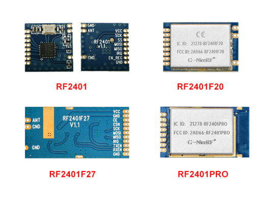
RF2401
The RF2401 series wireless modules are designed for long-range, low-power, and high-sensitivity FSK wireless digital communication within the 2.4GHz ISM global license-free band. These modules utilize wireless chips designed by a top European RF company. In addition to their low cost, small size, and product stability, they boast a maximum transmission power of 10dBm, a receive current of 7mA, and a tested receive sensitivity of -115dBm, allowing for a maximum range of up to 500 meters. This significantly surpasses similar 2.4GHz wireless modules of its kind. The RF2401 series can be widely used in daily life and activities that require wireless connectivity.
RF2401PRO
The RF2401PRO 2.4GHz wireless module utilizes the nRF24L01+ device from Nordic Semiconductor, which is a highly integrated 2.4GHz ISM band wireless transceiver chip. The major advantage of the RF2401PRO wireless module is its capability for transmitting voice and images. However, this feature results in a relatively shorter transmission distance compared to other modules.
Transmission Technologies and Characteristics:
LoRa1280: Utilizes LoRa modulation technology, known for its long-range communication and low power consumption characteristics, suitable for applications requiring long-range and low-power operation.
RF2401PRO: Features excellent transmission performance, supports high-speed data transmission, suitable for applications with high performance requirements.
RF2401: Typically employs FSK modulation, suitable for general wireless communication applications, and offers a lower price point.
Power Consumption and Battery Life:
LoRa1280 and RF2401PRO are both designed with low-power modes, capable of extending the battery life of devices, making them suitable for long-term operation and battery-powered applications. RF2401, while generally not as efficient in power consumption as LoRa1280 and RF2401PRO, also possesses some energy-saving characteristics.
Data Transmission Rates:
LoRa1280: Offers relatively low data transmission rates, typically suitable for applications requiring low-speed data transmission.
RF2401PRO: Provides higher data transmission rates, suitable for applications requiring fast data transfer.
RF2401: Typically offers moderate data transmission rates, suitable for general wireless communication needs.
Flexibility and Configuration Options:
RF2401PRO: Generally provides more configuration options and flexibility, allowing for tailored configurations based on specific application requirements.
LoRa1280: Also offers some configuration options, but not as diverse as RF2401PRO.
RF2401: Typically simpler with relatively fewer configuration options.
Application Fields:
LoRa1280: Suitable for applications requiring long-range, low-power communication, such as IoT (Internet of Things), agricultural monitoring, etc.
RF2401PRO: Suited for applications demanding higher transmission rates, such as remote control, sensor networks, etc.
RF2401: Suitable for general wireless communication needs, such as simple remote control, data transmission, etc.
2.4GHz wireless modules, as an important communication tool, have a very broad application outlook. Their application points are based on network protocols developed around their high-speed transmission rates, hence their advantages and disadvantages are also quite evident.
0 notes
Text
Here are the capabilities so far of our Inhouse design of the Rocket Flight Computer. This flight computer is designed for rockets 38mm in diameter or greater and will fit inside a 38mm tube coupler. Dimensions are 4.0in x 1.25in x 0.5in, not including the antenna more or less Flight-ready for supersonic flights to over 24K feet and Mach 2.0. For large or high-power projects, a commercially available backup computer is strongly recommended. --------FEATURES---------- Full-featured dual deploy/multi-stage/air start rocket flight computer capable of 100,000ft or more Tilt-sensing lockout for ignition of second stages and/or air starts Live telemetry over fil NRF24L01+PA+LNA compatibles with Arduino – 2 Mbit/s – 1100 metres And Bluetooth BLE 6 high-current pyro outputs with continuity checks Advanced MEMS sensor package: GNSS, accelerometers, gyroscope, magnetometer, barometer, and LoRa radio High Data-Capture rate: approximately 50,000 samples per second recorded to SD card --1000Hz 3-axis digital 24G and 100G accelerometer data logging --1000Hz 3-axis digital 2000dps gyroscope data logging --1000Hz of flight events & continuity data logging --1000Hz of sensor-fuzed speed & altitude --100Hz of pitch, yaw, roll rotation --40Hz of of magnetic data logging and magnetic roll --30Hz-100Hz of digital barometric data logging (Altitude, pressure, temperature) --30Hz of main battery voltage (1400Hz during pyro events) --5Hz-25Hz of GNSS data logging (chip-dependent data rates & constellations) --Separate data file for each flight up to 100 flights Simple, easy-to-use configuration interface through the SD card --User Selectable Flight Mode: Single-Stage, Two-Stage, Air start, or Booster --Configurable Apogee delay --Optional Audible Battery Voltage report at startup --Optional Magnetic Switch Startup & Shut-down --Pre-flight audible reporting options: Perfect flight or Marsa --User selectable telemetry frequency & power settings --8 configurable servo outputs (8 powered) +4 Multy prepose --User-selectable inflight brownout recovery Mach immune, sensor-fusion-based apogee event Barometric-based main deploy event Audible pre-flight continuity report Audible Post-flight max altitude & speed report Mount in any orientation, automatic orientation detection with built-in self-calibration mode Bench-test mode activated w/ tactile button, user configurable status messages over USB Serial A report in SI or Metric units Compatible with Teensy 4.1 --Connect any sensor to any available I2C or SPI bus --Create your own custom setup with configurable pins for continuity, firing, and servos --Connect UBLOX GPS unit to any available HW Serial port From OpenAI: Incorrect API key provided.
0 notes
Text
Flipper Zero NRF24 Module Build

This was my first attempt at building an NRF24 add on module for Flipper Zero. It uses a $2 NRF24L01+PA+LNA module with external antenna and a $0.13 AMS1117 5V to 3.3V Step Down Power Supply Buck module. It's possible to just power it directly from Flipper Zero's 3.3V pin, but that is shared with the SD card, so that makes it not hot-swappable. If you try to plug or unplug the module while your Flipper is on, you risk corrupting the SD card. By connecting it to the 5V pin instead, you can hot swap with no issues and that makes it more convenient.


I used a prototype board that has been cut down to the required size, and soldered some male header pins under it to connect to Flipper Zero's GPIO pins. Above it, I just soldered some Female header pins to plug the NRF24 module in, and I wired everything together. Please refer to the pinout below courtesy of UberGuidoZ and more details can also be found here. The only thing I did differently from the below is to connect VCC pin 2 on the NRF24 module to the Step Down Power Supply's VOUT, and wired the Flipper Zero's 5V to the VIN of the power supply module. Ground from Flipper Zero's pin 8 will go to the power supply module and GND pin 1 of the NRF24 module.

One last thing, I also soldered a 10uF capacitor to the NRF24 module across the VCC & GND as recommended in the link I shared above for reference. Pay attention to the negative of the capacitor! That's it, you should be able to plug it into your Flipper Zero and test it out. So far, I have not been able to find any device that is susceptible to mouse jacking yet, so this isn't very exciting so far ... Haha!
Here's another video that you can refer to, but his is a simpler build without the additional step down power supply module. To see what mouse jacking is like, check out this video.
0 notes

Video
youtube
How to Make Walkie Talkie Using Arduino --------------------------------------- Walkie-talkie using Arduino, humm.. sounds interesting isn't it? Alright, lets spend some time today and design and understand this fairly simple circuit, and lets find out how our expectations are challenged by the reality.
2 notes
·
View notes
Photo

* 🇧🇷 Walduininho V2 com módulo nrfl2401 . Comunicação entre dispositivos testada agora é transformar tudo em uma única placa (SMD) para embarcar em um projetos na sua fase final ------------------------ youtube.com/ProjetosEletronicos ------------------------ 🇺🇸 Walduininho V2 with module nrfl2401 . Communication between devices tested now is to turn a single board (SMD) to projects in its final phase ------------------------ #arduino #arduinouno #arduinonano #nrf24l01 #comunicação #dispositivos #projeto #embarcado #engineering #engenharia #smd #walduininho #v2 #iot #walproj #projetosmaker #projetoseletronicos #hardware #software (em Projetos Eletronicos) https://www.instagram.com/p/COV4Cl-rHod/?igshid=1uaxqpt6fdbok
#arduino#arduinouno#arduinonano#nrf24l01#comunicação#dispositivos#projeto#embarcado#engineering#engenharia#smd#walduininho#v2#iot#walproj#projetosmaker#projetoseletronicos#hardware#software
2 notes
·
View notes
Video
instagram
Steuern einer LED mit einem Taster. Die Kommunikation findet dabei über zwei nRF24L01 Module am Arduino Nano V3 statt. #nrf24l01 #nrfl01 #arduinoproject #arduinonano #wireless #maker #diy #electronic #components #tech #techy #draegerit (hier: Stefan Draeger Software) https://www.instagram.com/p/CNNFVz7K7dz/?igshid=nduo5lhc0gwi
#nrf24l01#nrfl01#arduinoproject#arduinonano#wireless#maker#diy#electronic#components#tech#techy#draegerit
1 note
·
View note
Photo

NRF Transceiver Module #nrf #nrftransmitter #nrftx #nrf24l01 #nrfreceiver #tx #rx #electronics #tech #arduino #nordic #remote #rc #remotecontrol https://www.instagram.com/p/CiKqb0mrw_Q/?igshid=NGJjMDIxMWI=
#nrf#nrftransmitter#nrftx#nrf24l01#nrfreceiver#tx#rx#electronics#tech#arduino#nordic#remote#rc#remotecontrol
0 notes
Video
youtube
Fastest Arduino RC Car using Coreless DC Motors and nRF24L01 RF module
RC cars are always fun to play with. Most of these cars today provide a huge torque to handle rough terrains, but there is something that was always lagging, its Speed!!.. So, in this project, you will build a totally different type of RC car using Arduino, the main objective of this car is to achieve maximum speed, by coreless DC motor for an RC car. These motors are normally used in drones and are rated for 39000 RPM which should be more than enough to quench our speed thirst. The car will be powered with a small lithium battery and can be controlled remotely using the nRF24L01 RF module.
0 notes
Text
Optimized NRF24 Transmitter (Part #3)
WHAT's NEW in PART #3?????
Watch, Subscribe and Share https://youtu.be/9wyBcw9BEec
nrf24 #nrf24l01 #transmitter #receiver #arduino #quadcopter #arduinoproject, #ardujimmy
0 notes
Link
2.4 GHz RF module RF2401F20 has obtained many certifications such as CE-RED, FCC ID, IC ID(Canada certification), TELEC(Japan certification) and ROHS.
0 notes
Text
Arduino Telsiz Nasıl Yapılır
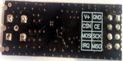
Adım 2: NRF24L01 modüllerini devre şemasında gösterildiği gibi aşağıdaki sırayla bağladım. CE dijital pin numarası 7, CSN pin numarası 8, SCK dijital pin 13, MOSI dijital pin 11, MISO dijital pin 12 ve IRQ dijital pin 2.
5G ve 5G özellikli cihazlar çağında yaşıyoruz; ancak, telsiz sistemi ve RF iletişim sistemi gibi eski teknolojiler, uzak, kısa mesafe, ucuz ve düşük maliyetli iletişimin gerekli olduğu senaryolarda hala çok önemlidir. Örneğin, bir bina veya ağır yük taşıyan inşaat şirketiniz varsa, işçilerinizin koordineli çalışmak için birbirleriyle iletişim kurması gerekir. Bir telsizin yardımıyla, birbirleriyle iletişim kurabilirler ve kısa bir masaj veya talimatlar yayınlayabilirler, sadece diğer işçilere ses iletmek için “PTT” düğmesine basarak komutları dinleyip takip edebilirler. Başka bir uygulama akıllı kasklarda olabiliruzun bir sürüş sırasında bir sürü bisikletçi arasında iletişim kurmak için, burada önerilen model bir seferde altı kişi arasında iletişim kurabilir. Diğer kısa menzilli kablosuz ses iletim projelerine göz atmak istiyorsanız , bağlantıları kullanarak IR Tabanlı Kablosuz Ses Verici ve Li-Fi Ses Verici projesini ziyaret edin .
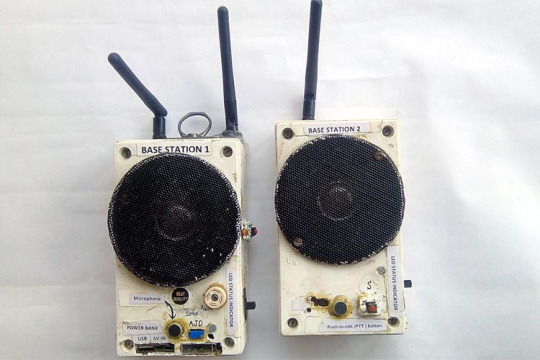
NRF24L01 RF Modülünü kullanan Walkie Talkie
Bu projenin ana bileşeni NRF24L01 RF modülü ve beyin veya işlemci olan Arduino Uno'dur . Bir servo motoru uzaktan kontrol ederek Nrf24L01 ile Arduino arasında nasıl arayüz kurabileceğimizi öğrendik . Bu proje için NRF24L01 RF modülü, dijital iletişim ortamına göre çeşitli avantajlara sahip olduğu için seçilmiştir. Bu sahip 2,4 GHz çok yüksek frekanslı ISM bandını ve veri hızı 250kbps, 1 Mbps, 2 Mbps olabilir. 1Mhz aralığı arasında 125 olası kanal vardır, böylece modül 125 farklı kanal kullanabilir, bu da tek bir yerde 125 bağımsız çalışan modemden oluşan bir ağa sahip olmayı mümkün kılar.
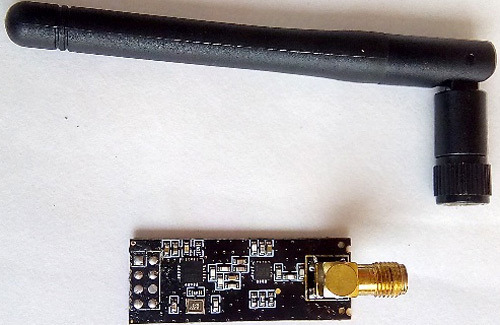
En önemlisi, NRF24L01 sinyalleri polis telsizi ve demiryolu telsizi gibi diğer telsiz sistemleri ile çakışmaz veya çapraz arayüz oluşturmaz ve diğer telsizleri rahatsız etmez. Tek bir nrf24l01 modülü, alıcı durumdayken diğer 6 nrf24l01 modülü ile iletişim kurabilir. Ayrıca, ek bir avantaj olan düşük güç tüketimi modülüdür. Yaygın olarak bulunan ve yaygın olarak kullanılan iki tür NRF24L01 modülü vardır, biri NRF24L01 + ve diğeri dahili antenli NRF24L01 + PA + LNA (aşağıda gösterilmiştir). NRF24L01 +
yerleşik bir antene ve sadece 100 metre menzile sahiptir. Sadece iç mekan kullanımı için iyidir ve dış mekan uzun mesafeli iletişim için uygun değildir. Ayrıca, verici ve alıcı arasında bir duvar varsa, sinyal iletimi çok zayıftır. Harici antenli NRF24L01 + PA + LNA bir sahip PA olduğunu artırır iletiminden önce sinyalin gücü. LNA, Düşük Gürültülü Amplifikatör anlamına gelir. Açıktır, gürültüyü filtreler ve antenden alınan sinyalin son derece zayıf ve belirsiz düşük seviyesini artırır. Bu sinyalin kullanışlı seviyelerini yapımında yardımcı olur ve sahip olduğu 2dB'lik dış anteni o hangi aracılığıyla , üzerinde hava aralığı kapsamının 1000 metreden iletmek açık hava telsiz iletişim projelerimiz için mükemmeldir.
Arduino tabanlı Walkie Talkie için Gerekli Bileşen
Harici 2DB antenli NRF24L01 + PA + LNA (2 adet)
Arduino UNO veya Arduino'nun herhangi bir sürümü
Ses yükseltici (2 adet)
Mikrofon devresi: Kendiniz yapabilir (daha sonra tartışılacaktır) veya bir ses sensörü modülü satın alabilirsiniz.
DC'den DC'ye yükseltme güçlendirici modülü (2 adet)
3.3V AMS1117 voltaj regülatörü modülü
Güç gösterge LED'i (2 adet)
470 ohm direnç (2 adet)
4 inç hoparlör (2 adet)
basma düğmesi (bas-konuş düğmesi için)
PTT düğmesinin yapılması için 104 PF (2 adet)
NRF24L01 için 100 NF kapasitör (2 adet)
PTT düğmesi için 1k direnç (2 adet)
2 set li-ion pil
Li-ion pil şarj ve pil koruma modülü (2 adet)
Bazı jumper teli, erkek başlık pimi, noktalı vero kartı
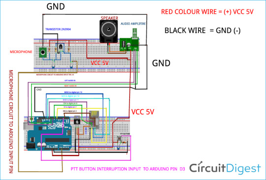
Arduino Walkie Talkie Devre Şeması
Arduino Walkie Talkie için tüm devre şeması aşağıdaki resimde gösterilmektedir. Devre şeması PTT düğmesi, mikrofon devresi ve stereo ses çıkışı dahil tüm bağlantıları gösterir.
Önemli: NRF24L01 modülü voltaj giriş aralığı 1.9v ila maksimum 3.6 volt arasındadır ve voltaj ve akım kararlılığı için + VCC ve - GND'ye 100nf kapasitör kullanmanız gerekir, ancak nrf24l01 modülünün diğer pimleri 5 volt sinyale tolere edebilir seviyeleri.
Adım 1: Ev yapımı özel PCB ve Arduino Atmega328p kartı yapmaya başladım. IC Atmega328p'yi programcıya koydum ve yanıp söndüm ve kodu yükledim. Daha sonra, Atmega328p IC'ye (PB6, PB7) pin 9 ve 10'a 16 MHz kristal ekledim. Özel yapım PCB'm ve programlanmış IC'ye sahip monte edilmiş kartın resimleri aşağıda gösterilmiştir.

Adım 2: NRF24L01 modüllerini devre şemasında gösterildiği gibi aşağıdaki sırayla bağladım. CE dijital pin numarası 7, CSN pin numarası 8, SCK dijital pin 13, MOSI dijital pin 11, MISO dijital pin 12 ve IRQ dijital pin 2.
Güç kaynağı için, gerilimi önce 5 volttan 3.3 v'ye iyi akım kararlılığı ile düşürmeniz gerekir. Ayrıca, nrf24l01 modülünün VCC'sine ve toprağına 100nF kapasitör koymanız gerekir. Bu nedenle, 3.3 volt voltaj regülatörü olan AMS1117'yi kullandım , modül aynı zamanda proje boyutunuzu da küçültür ve kompakt hale getirir.
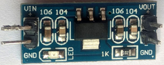
Bu voltaj regülatör kartını kendiniz yapmak istiyorsanız, sadece 3,3 voltluk regülatör IC'yi satın alabilir ve hassas bir cihaz olduğu için RF modülünüz için çok önemli olduğu için bazı kapaklar, giriş ve çıkışta direnç ekleyerek yapabilirsiniz. Veya , Breadboard güç kaynağı projesinde yaptığımız gibi 3.3V Ayarlı bir devre oluşturmak için LM317 değişken voltaj regülatörünü kullanabilirsiniz .
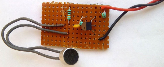
Adım 3: Devre şemasında gösterildiği gibi bir ses sensörü satın alabilir veya basit bir mikrofon devresi yapabilirsiniz. Sadece bir transistör- 2n3904 NPN transistörden oluşur . Aşağıdaki resimde bir Vero kartı üzerine inşa edilmiş ev yapımı mikrofon devresi gösterilmektedir. Daha fazla bilgi için bu basit ses ön amplifikatör devresini de kontrol edebilirsiniz .
Daha iyi anlamak için, aşağıda gördüğünüz gibi bileşen değerleriyle tüm bağlantının başka bir temsilini yaptım
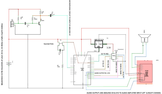
Bağlantı çok basit, Ses Amplifikatörünü çalıştırmak için 3.7V ila 5V güç kaynağı gerekir. Arduino pin 9 ve 10'dan toprak pin ile birlikte sol kanal ve sağ kanal ses girişi, devre şemasında gösterildiği gibi bu amplifikatör modülü için giriş olarak verilmelidir. Benim durumumda, tek bir 4 inç 8 ohm hoparlör kullandım ve sadece sağ kanal çıkışını kullandım. İsterseniz, bu modülle iki hoparlör kullanabilirsiniz.
Adım 5: Ardından, basit bir basma düğmesi kullanarak PTT anahtarını oluşturdum. Düğmeye basıldığında anahtarın sıçramasını veya düzensiz sinyalleri önlemek için 104PF veya 0.1 uf kapasitör ekledim . Pin 4 şimdi kodlamaya kesilmiş bir pin atandığı için Arduino Digital pin D3 ile doğrudan bağlanmıştır.
Bir ses sinyali veya DATA paketleri iletirken NRF24L01 + PA + LNA daha fazla güç tüketir, bu nedenle daha fazla akım tüketir. PTT düğmesine aniden bastığınızda, güç tüketimi artar. Bu aniden artan yükü yönetmek için NRF24L01 + PA + LNA Modülünün iletim kararlılığı için + vcc ve Toprak üzerinde 100nF kapasitör kullanmanız gerekir.
Düğmeye basıldığında, Arduino kartı D3 pininde bir Arduino Kesintisi alır . Programda, Arduino'nun dijital pimi 3'ü giriş voltajını sürekli kontrol ettiğini ilan edeceğiz. Giriş voltajı düşükse, telsizi alma modunda tutar ve dijital pin numarası 3 yüksekse, mikroişlemci aracılığıyla mikrofon işlemi tarafından alınan ses sinyalini göndermek ve iletmek için telsizi iletim moduna geçirir. Harici antenli NRF24L01 + PA + LNA.
Adım 6: Güç kaynağı için bu Li-ion pili seçtim . Arduino IC Atmega328p, NRF24L01 + PA + LNA, ses yükseltici, PTT düğmesi ve Mikrofon devresi gibi tüm bileşenlere güç vermek için, aşağıda gösterildiği gibi bu proje için 2 set Li-ion pil kullandım.
İyi bir hücrenin voltaj seviyesi 3.8v ila 4.2 volt arasındadır ve şarj voltajı sadece 4v ila 4.2 volttur. Bilmek için daha lityum piller hakkında Bağlı makaleye bakabilir. Bu piller taşınabilir elektronik cihazlarda ve elektrikli araçlarda çok popülerdir . Ancak Li-ion pil hücreleri diğer piller kadar sağlam değildir, aşırı şarj ve deşarjdan çok hızlı korumaya ihtiyaç duyarlar, yani şarj / deşarj akımı ve voltajı güvenli sınırlar içinde tutulmalıdır. Bu nedenle, en pervane Li-ion pil şarj modülünü kullandım - TP4056 . Bu modülü daha önce bir Taşınabilir Güç Bankası oluşturmak için kullandık, bu kartta daha fazla ayrıntı için bunu kontrol edebilirsiniz .
Adım 7: Arduino atmega328p, Ses Amplifikatörü, mikrofon devresi, PTT düğmesi her şey 5 volt'a ihtiyaç duyduğundan dc yükseltici modülüne 2 Amp dc dc kullandım, ancak pilim sadece 3.7V ila 4.2V tedarik edebilir, bu yüzden bir boost dönüştürücüye ihtiyacım var 1 Amp'dan fazla kararlı güç çıkışı ile 5V'a ulaşmak için.
Devreyi kurduktan sonra, küçük bir kasaya monte edebilirsiniz. Plastik bir kutu kullandım ve devrelerimi aşağıdaki resimde gösterildiği gibi yerleştirdim
Walkie Talkie Arduino Kodu
Arduino telsizi için komple program bu sayfanın alt kısmında bulunabilir. Bu bölümde, programın nasıl çalıştığını tartışalım. Buraya gelmeden önce, aşağıda listelenen bazı Kütüphaneleri eklemeniz gerekir.
nRF24 Kütüphanesi
nRF24 Ses Kütüphanesi
Maniaxbug RF24 Kütüphanesi
Radyo ve Ses Kütüphanesi başlıklarını aşağıda gösterildiği gibi ekleyerek programlamaya başlayın
#include <RF24.h> #include <SPI.h> #include <RF24Audio.h> #include "printf.h" // General includes for radio and audio lib
7 ve 8 numaralı pinlerde RF Radyoyu başlatın ve ses radyo numarasını 0 olarak ayarlayın. Ayrıca, pin 3'teki ppt düğmesini başlatın.
RF24 radio(7,8); // Set radio up using pins 7 (CE) 8 (CS) RF24Audio rfAudio(radio,0); // Set up the audio using the radio, and set to radio number 0 int talkButton = 3;
Kurulum fonksiyonunun içinde, hata ayıklama için seri monitörü 115200 baud hızında başlatın. Daha sonra ppt düğmesini connect pimini 3 kesinti pimi olarak başlatın.
void setup () { Serial.begin (115200); printf_begin (); radio.begin (); radio.printDetails (); rfAudio.begin (); pinMode (talkButton, INPUT); // düğme konuşması abutton press attachInterrupt (digitalPinToInterrupt (talkButton), konuşma, CHANGE) olup olmadığını kontrol etmek için kesmeyi ayarlar ; // rfAudio.receive () almak için her modül için varsayılan durumu ayarlar ; }
Sonra, kesmeye yanıt olarak çağrılan talk () adında bir fonksiyonumuz var. Program, düğmeye basılıp basılı tutulursa düğmenin durumunu kontrol eder ve sesi göndermek için iletim moduna girer. Düğme bırakılırsa alma moduna girer.
void setup() { Serial.begin(115200); printf_begin(); radio.begin(); radio.printDetails(); rfAudio.begin(); pinMode(talkButton, INPUT);//sets interrupt to check for button talk abutton press attachInterrupt(digitalPinToInterrupt(talkButton), talk, CHANGE); //sets the default state for each module to receive rfAudio.receive(); }
Bu projenin tam çalışması, aşağıdaki bağlantıda bulunan videoda bulunabilir. Walkie Talkie çalışma sırasında biraz gürültü çıkarıyor, bu nRF24L01 Modülünün taşıyıcı frekansından gelen gürültü. İyi bir ses sensörü veya mikrofon modülü kullanılarak azaltılabilir. Bu proje hakkında herhangi bir sorunuz varsa, bunları aşağıdaki yorum bölümünde bırakabilirsiniz. Forumlarımızı diğer teknik sorularınıza hızlı yanıtlar almak için de kullanabilirsiniz.
Kod
#include <RF24.h> #include <SPI.h> #include <RF24Audio.h> #include "printf.h" // General includes for radio and audio lib RF24 radio(7,8); // Set radio up using pins 7 (CE) 8 (CS) RF24Audio rfAudio(radio,0); // Set up the audio using the radio, and set to radio number 0 int talkButton = 3; void setup() { Serial.begin(115200); printf_begin(); radio.begin(); radio.printDetails(); rfAudio.begin(); pinMode(talkButton, INPUT); //sets interrupt to check for button talk abutton press attachInterrupt(digitalPinToInterrupt(talkButton), talk, CHANGE); //sets the default state for each module to receiver rfAudio.receive(); } //void talk() //Called in response to interrupt. Checks the state of the button. //If the button is pressed (and held) enters transmit mode to send //audio. If button is release, enters receive mode to listen. void talk() { if (digitalRead(talkButton)) rfAudio.transmit(); else rfAudio.receive(); } void loop() { }
#arduino#arduinoproject#arduino telsiz yapımı#arduino projeleri#arduino iot projeleri#raspberrypi#Node-Red#Node Red nedir?#Node Red Nasıl Kurulur?#esp8266#nrf24l01#arduino telsiz nasıl yapılır#arduino telsiz nedir#arduino 24l01 uygulamaları
0 notes
Text
Wireless tripwire with rx and tx module which will minimize your active window or lock you laptop/pc or do some custom scripts.
📥Download code from http://bit.ly/2RBFMPM
▶️Watch video @ https://youtu.be/VdS4yWXiQcU
🌐https://diyusthad.com/2019/12/tripwire-automatically-minimizes-your-tabs-when-someone-walks-by.html
#tripwire #daytripper #Arduino #arduinopromini #arduinopromicro #diyusthad #arduinoprojects #nrf24l01
0 notes
