#open circuit voltage tester
Explore tagged Tumblr posts
Visit Tumblr Blog
Explore Tumblr blogs with no restrictions, modern design and the best experience.
Last Seen Tumblr Blogs


Fun Fact
Tumblr has 4 main sources of revenue.
Text
How OCV Tester Machines Power Battery Performance & Quality?
The Open Circuit Voltage (OCV) Tester Machine is a critical piece of battery testing equipment used extensively across the lithium-ion battery manufacturing sector. It measures the voltage of a battery without applying any load, offering vital insights into its State of Charge (SoC), State of Health (SoH), and consistency.

By conducting non-invasive voltage checks, OCV testing helps ensure batteries meet rigorous safety and performance standards before being installed in electric vehicles (EVs), energy storage systems (ESS), and consumer electronics.
How Does an OCV Tester Work?
Battery Placement: The battery is carefully placed in the tester to align precisely with high-accuracy probes.
Voltage Measurement:
High-precision probes contact battery terminals.
Measures open-circuit voltage with zero current draw.
Achieves millivolt-level accuracy.
Data Processing:
Compares voltage against predefined parameters.
Identifies irregularities linked to aging or defects.
Sorting & Classification:
Categorizes batteries based on OCV results.
Group similar cells for consistent battery pack assembly.
Flag defective batteries for quality control.
Mechanism Behind OCV Testing
OCV testing operates on the principle that the battery's open-circuit voltage correlates with its charge level and overall health.
Key features include:
High-precision electronics using advanced voltmeters.
High input impedance probes to ensure zero current flow.
Automated handling systems for high-speed processing.
Temperature compensation algorithms for accurate diagnostics.
Importance of OCV Testing
Quality Assurance:
Verifies adherence to design specifications.
Detects early-stage degradation.
Manufacturing Defect Detection:
Highlights issues like internal shorts or faulty coatings.
Battery Grading:
Ensures matched cells for EV and ESS packs.
Enhanced Safety & Reliability:
Identifies cells prone to thermal runaway or failures.
Formation & Aging Analysis:
Supports SEI layer monitoring during charge-discharge cycles.
Applications Across Industries
Electric Vehicles (EVs): Boost battery life and reliability.
Consumer Electronics: Ensures consistent performance in devices.
Energy Storage Systems (ESS): Guarantees long-term operation.
Aerospace & Defence: Assures performance under extreme conditions.

Selecting the Right OCV Tester
When choosing an OCV tester, manufacturers should consider:
Accuracy: Millivolt-level measurement capabilities.
Automation: For high-throughput production lines.
Data integration: For real-time analysis and traceability.
Compatibility: Across chemistries and battery formats.
Conclusion
From cell sorting to quality control, the OCV Tester Machine is essential for creating safe, high-performing lithium-ion batteries. As demand for batteries in EVs, ESS, and consumer electronics grows, OCV testing stands as a pillar of battery manufacturing efficiency.
#battery quality control#battery testing equipment#Lithium-Ion Battery Testing#OCV tester machine#OCV testing in lithium-ion batteries#open circuit voltage tester#state of charge (SoC) measurement
0 notes
Text
From Circuits to Solutions: Practical Projects to Elevate Your EE Skills
From Breadboards to Breakthroughs” encapsulates the journey of an aspiring electrical engineer as they evolve from basic circuit experiments to advanced, real-world engineering projects. Hands-on projects are essential for building practical skills, reinforcing theoretical knowledge, and preparing for professional challenges. Below is a guide to project-based learning that can help you improve your electrical engineering (EE) skills at every stage.
Beginner Projects: Building Foundations
Simple LED Circuit
What you learn: Basic circuit design, current and voltage concepts, use of resistors and LEDs.
Tools: Breadboard, jumper wires, resistors, LEDs, battery.
Battery Tester
What you learn: Measuring voltage and current, basic instrumentation, and safety practices.
Water Level Indicator
What you learn: Sensor integration, simple logic circuits, and practical applications.
Logic Gates and Digital Circuits
What you learn: Boolean logic, digital circuit fundamentals, and troubleshooting.
DIY Switch Circuits
What you learn: Circuit switching, input/output devices, and practical wiring.
Intermediate Projects: Expanding Your Skills
Infrared Security System
What you learn: Sensor-based security, signal processing, and system integration.
Digital Voltmeter
What you learn: Instrumentation, analog-to-digital conversion, and measurement accuracy.
Solar Charger
What you learn: Renewable energy concepts, power management, and circuit protection.
Motor Control Circuits
What you learn: Driving motors, pulse-width modulation (PWM), and power electronics.
Heart Rate Monitor
What you learn: Biomedical instrumentation, sensor interfacing, and signal filtering.
Advanced Projects: Real-World Breakthroughs
Smart Home Automation System
What you learn: IoT, wireless communication (Bluetooth, Wi-Fi), and system integration.
Wireless Power Transfer System
What you learn: Inductive coupling, resonant circuits, and energy efficiency.
Dual Axis Solar Power Tracker
What you learn: Mechatronics, sensor feedback, and renewable energy optimization.
Smart Energy Meter
What you learn: Real-time data monitoring, wireless communication, and energy management.
DIY Quadcopter or Drone
What you learn: Embedded systems, motor control, wireless communication, and robotics.
Why Hands-On Projects Matter
Resume Building: Practical projects demonstrate your skills to potential employers and can help you land internships or jobs
Theory Application: Projects bridge the gap between classroom learning and real-world engineering challenges.
Skill Discovery: Experimenting with different projects helps you identify your interests and strengths.
How to Get Started
Gather Basic Tools: Invest in a quality breadboard, jumper wires, resistors, capacitors, LEDs, and a multimeter.
Start Simple: Begin with basic circuits and gradually tackle more complex projects as your confidence grows.
Use Online Resources: Take advantage of tutorials, simulation tools, and open-source project guides.
Join Maker Communities: Engage with online forums, local maker spaces, and engineering clubs for support and inspiration.
Document Your Work: Keep a project journal, take photos, and share your progress on platforms like GitHub or LinkedIn.
Conclusion
Arya College of Engineering & I.T. is one of the best colleges of Jaipur, which is progressing from breadboard experiments to advanced engineering projects is a transformative process that builds both technical expertise and problem-solving confidence. By systematically advancing through beginner, intermediate, and advanced projects, you will develop a robust skill set that prepares you for the challenges and opportunities of a career in electrical engineering.
1 note
·
View note
Text
From Breadboards to Breakthroughs: Hands-On Projects to Improve Your EE Skills

From Breadboards to Breakthroughs” encapsulates the journey of an aspiring electrical engineer as they evolve from basic circuit experiments to advanced, real-world engineering projects. Hands-on projects are essential for building practical skills, reinforcing theoretical knowledge, and preparing for professional challenges. Below is a guide to project-based learning that can help you improve your electrical engineering (EE) skills at every stage.
Beginner Projects: Building Foundations
Simple LED Circuit
What you learn: Basic circuit design, current and voltage concepts, use of resistors and LEDs.
Tools: Breadboard, jumper wires, resistors, LEDs, battery.
Battery Tester:
· What you learn: Measuring voltage and current, basic instrumentation, and safety practices.
Water Level Indicator
What you learn: Sensor integration, simple logic circuits, and practical applications.
Logic Gates and Digital Circuits: What you learn: Boolean logic, digital circuit fundamentals, and troubleshooting.
DIY Switch Circuits: What you learn: Circuit switching, input/output devices, and practical wiring.
Intermediate Projects: Expanding Your Skills
Infrared Security System: What you learn: Sensor-based security, signal processing, and system integration.
Digital Voltmeter: What you learn: Instrumentation, analog-to-digital conversion, and measurement accuracy.
Solar Charger: What you learn: Renewable energy concepts, power management, and circuit protection.
Motor Control Circuits
What you learn: Driving motors, pulse-width modulation (PWM), and power electronics.
Heart Rate Monitor: What you learn: Biomedical instrumentation, sensor interfacing, and signal filtering.
Advanced Projects: Real-World Breakthroughs
Smart Home Automation System: What you learn: IoT, wireless communication (Bluetooth, Wi-Fi), and system integration.
Wireless Power Transfer System: What you learn: Inductive coupling, resonant circuits, and energy efficiency.
Dual Axis Solar Power Tracker: What you learn: Mechatronics, sensor feedback, and renewable energy optimization.
Smart Energy Meter: What you learn: Real-time data monitoring, wireless communication, and energy management.
DIY Quadcopter or Drone: What you learn: Embedded systems, motor control, wireless communication, and robotics.
Why Hands-On Projects Matter
Resume Building: Practical projects demonstrate your skills to potential employers and can help you land internships or jobs
Theory Application: Projects bridge the gap between classroom learning and real-world engineering challenges.
Skill Discovery: Experimenting with different projects helps you identify your interests and strengths.
How to Get Started
Gather Basic Tools: Invest in a quality breadboard, jumper wires, resistors, capacitors, LEDs, and a multimeter.
Start Simple: Begin with basic circuits and gradually tackle more complex projects as your confidence grows.
Use Online Resources: Take advantage of tutorials, simulation tools, and open-source project guides.
Join Maker Communities: Engage with online forums, local maker spaces, and engineering clubs for support and inspiration.
Document Your Work: Keep a project journal, take photos, and share your progress on platforms like GitHub or LinkedIn.
Conclusion
Arya College of Engineering & I.T. is one of the best engineeering college in Jaipur, which is progressing from breadboard experiments to advanced engineering projects is a transformative process that builds both technical expertise and problem-solving confidence. By systematically advancing through beginner, intermediate, and advanced projects, you will develop a robust skill set that prepares you for the challenges and opportunities of a career in electrical engineering.
Source: Click Here
#best btech college in jaipur#top engineering college in jaipur#best private engineering college in jaipur#best engineering college in rajasthan#best btech college in rajasthan#best engineering college in jaipur
0 notes
Text

Abstract Lightning surges pose a significant threat to electronic devices, making them a crucial topic in electromagnetic compatibility (EMC) research. The IEC 61000-4-5 surge tester provides a standardized method for evaluating the surge immunity of electrical and electronic equipment. This paper delves into the working principles of lightning surge generators, testing methodologies, and applications, with a focus on the LISUN SG61000-5 Surge Generator. By analyzing this device’s technical specifications and practical use cases, this study aims to provide insights into surge protection design and testing for electronic equipment. 1. Introduction With the rapid advancement of electronic technology, electronic devices are widely used in various fields. However, lightning strikes and power system switching operations can generate high-energy transient overvoltages (surges), causing serious damage to these devices. Evaluating and improving surge immunity is an essential part of EMC research. The IEC 61000-4-5 surge tester plays a critical role by defining a standardized testing methodology for surge immunity assessment. 2. Overview of IEC 61000-4-5 Standard The IEC 61000-4-5 standard, published by the International Electrotechnical Commission (IEC), defines test methods and requirements for surge immunity evaluation, specifically addressing transient overvoltages caused by switching and lightning strikes. The standard outlines waveform specifications, test levels, test equipment, and test procedures to provide a uniform assessment framework. The latest version, IEC 61000-4-5:2014, has introduced updates and improvements to testing methodologies and technical requirements. Surge Generator SG61000-5 3. Working Principle of Lightning Surge Generators Lightning surge generators are designed to simulate transient overvoltages caused by lightning strikes or switching operations to evaluate the immunity of electronic devices. The core function of these generators is to produce standardized surge waveforms in accordance with IEC 61000-4-5, such as: • 1.2/50μs open-circuit voltage waveform • 8/20μs short-circuit current waveform These waveforms are applied to the Equipment Under Test (EUT) through Coupling/Decoupling Networks (CDN) to assess its surge immunity. 4. Surge Test Methodology 4.1 Test Subjects and Application Scope The IEC 61000-4-5 surge tester is applicable to power-connected devices, communication equipment, industrial control systems, and more. The primary objective of surge testing is to assess the immunity of these devices against transient overvoltages, ensuring their reliability in real-world conditions. 4.2 Surge Waveforms The LISUN SG61000-5 surge generator produces two fundamental surge waveforms: • Open-circuit voltage waveform (1.2/50μs) • Voltage rise time: 1.2μs ±20% • Voltage duration: 50μs ±20% • Short-circuit current waveform (8/20μs) • Current rise time: 8μs ±20% • Current duration: 20μs ±20% 4.3 Test Configurations Surge tests are typically performed in two ways: • Common-mode test (Line-to-Ground): The surge is applied between the phase line (L) or neutral line (N) and the ground (PE), simulating lightning-induced surges propagating through grounding networks. • Differential-mode test (Line-to-Line): The surge is applied between the phase line (L) and the neutral line (N), simulating transient overvoltages within the power grid. 4.4 Application of Surges The LISUN SG61000-5 surge tester applies surges through its built-in Coupling/Decoupling Network (CDN) to ensure compliance with standard testing conditions. The surges can be applied with positive, negative, or alternating polarity for comprehensive evaluation. 5. Test Result Analysis Test results can be categorized as follows: • Class A: The device operates normally after the test without degradation. • Class B: The device may experience temporary functional interruptions but recovers without user intervention. • Class C: The device requires manual intervention to resume normal operation. • Class D: The device is permanently damaged and fails to recover. 6. Conclusion and Applications The LISUN SG61000-5 surge generator is fully compliant with the IEC 61000-4-5 standard, making it an ideal tool for power systems, communication networks, automotive electronics, and household appliances. Its precision and automation make it highly valuable for EMC laboratories and electronic product manufacturers. As electronic devices become more complex, surge testing technology will continue evolving to meet stricter EMC requirements. LISUN and other manufacturers will keep improving testing solutions to ensure safety and reliability in electronic products. Read the full article
0 notes
Text
How Can Electrical Repair Extend the Life of Home Appliances?
Proper electrical maintenance confirms the protection of your home appliances for longer. Electrical issues such as old wiring, faulty installations, and power fluctuations can directly affect appliances, making electrical repair unavoidable. Residential electrical services thus maintain the efficiency of your electrical system, the appliances that use it, and the length of their valid service life.

The Work of Electrical Restorations
Electric circuits are delicate, and any defect that occurs often affects the performance of other appliances. Failure to seek the necessary repairs in the older works (wiring, circuits, etc.) will lead to extremely low performance. These faulty electrical circuits may consume more energy at such an inconsistent standard. Thus, regular Dallas Home Electrical repair services bring them back to their best possible functioning.
Key Electrical Troubleshooting Methods
To keep the appliances functioning at their best, electricians have rightly provided a wide variety of electrical troubleshooting methods that can be used to analyze and solve problems methodically. Among these are some of the more specific methods:
Checking Wire Connections
The tube connections attached to the openings might give way due to corrosion or other physical pressures, given the wear and tear brought by the elements throughout the years. Should this become a problem, an irregular appliance power supply is experienced. After the joints have been checked, occasionally tightening them will help provide a constant power flow to those appliances.
Checking Breakers
Electricians can reallocate appliance loads for balance or circuit brake disconnections if one circuit is overloaded.
Voltage Test
Power imbalances can destroy your appliances, but guesswork is denied for technical reasons. An electrician/cable worker uses a voltage tester to take readings and adjust voltages while ensuring optimal voltage distribution settings have been undertaken.
Opening and Switch Check
Faulty openings can spark, sometimes leading to unstable power that could damage linked appliances. Electricians can replace the outlets if the outlets prove faulty, ensuring that appliances last longer and are kept safe.
Benefits of Expert Electrical Repairment
Greater Energy Efficiency: Appliances operating on a stable voltage prove very capable, not just in functioning but in reducing the pressure on the energy bills.
Enhanced Safety: Proper repairs will prevent potential risks, such as possible electrical fires, shocks, or damage to the very same appliances being fixed.
Cost Savings: Regularly fixing electrical issues means preventing the more costly replacement of appliances.
Why Choose Professional Electrical Repairment in Dallas?
When you hire professional Dallas electrical restoration services, you are assured that your electrical installation has undergone a professional check with safety. For quality work in electrical restoration and advanced electrical troubleshooting techniques, contact the expert team at Tintowire Electric Company. They specialize in repairing electrical problems.
0 notes
Text
How to Install Infrared Sensors? Your Auto Garage Door Installation Guide!

Introduction
Installing infrared sensors for your automatic garage door is the most important part of safety installation to avoid accidents. These infrared sensors create an invisible beam across the door opening. They detect the presence of anything in the way of the door opening and prevent it from closing onto the object. Here is a detailed guide on how to install infrared sensors effectively so that you get the best from your auto garage door installation while having peace of mind.
Step 1: Gather Your Tools and Materials
Take a few moments to gather everything before you start with the installation. You will require:
Infrared sensors. Generally sold in pairs.
Screwdriver set
Wire strippers
Electrical tape
Voltage tester
Mounting brackets and screws usually come with the sensors
Protective goggles and gloves
Step 2: Turn Off Power
Safety first! Begin by disconnecting the power supply to your garage door opener. This can be done by unplugging it or turning off the circuit breaker. This precaution prevents any accidental activation while you’re working on the installation.
Step 3: Remove Old Sensors (if applicable)
If replacing old sensors, carefully unscrew them from their mounts and disconnect the wires. Use a voltage tester to confirm that there’s no power running through the system before proceeding with the new installation.
Step 4: Positioning the New Sensors
Mount your new infrared sensors on both sides of the garage door 6 inches off the floor. The ends must face toward each other to establish an uninterrupted beam, so mount it firmly with the supplied bracket and screws. Alignment is of utmost importance and can easily shift out of balance and render both sensors useless.
Step 5: Connect Wiring to Sensors
Now, it's time to connect the wiring. Use your wire strippers to remove about half an inch of insulation from the ends of each wire. Then, connect the positive and negative wires from each sensor to its respective terminals in the garage door opener unit. Usually the colours are matched; for example, white to white, black to black. Connect the connectors securely with the electrical tape wound over them.
Step 6: Secure All Connections
After all the connections are completed, check that everything is secure. There should be no exposed wires or wires likely to be pinched or damaged in operation. Any excess wiring should be tucked away neatly along walls or ceilings using staples or clips.
Step 7: Reconnect Power and Test
Now that everything is installed, it is time to re-power your garage door opener. Test the sensors: Close the door. This should reverse if something gets in its way of opening. This is important because if they're not set up correctly, your infrared sensors will be faulty.
Step 8: Tweak it
If everything goes according to plan, fine-tune any remaining adjustments to optimise performance. Check that both sensors have solid green lights, indicating they are properly aligned. If one or both lights are off, realign them until they work correctly.
Conclusion
Installing infrared sensors is a quite simple yet important operation that will guarantee your safety once you are done with auto garage door installation. Simply by following all the steps set forth, the garage door will glide into operation along with safeguarding people and pet safety from those accidents. As long as your sensors are appropriately installed and their maintenance is also performed, one will feel content and secure for many more years, getting the pleasure of living in comfort.
0 notes
Text
The Step-by-Step Guide to Installing Emergency Lighting

Emergency lighting is a crucial part of any building's safety system. Whether it's a commercial space, an industrial facility, or a residential building, proper emergency lighting installation ensures visibility during power outages and emergencies. This guide will walk you through the process, making it simple.
Why Is Emergency Lighting Important?
Emergency lighting helps people safely navigate power outages, fires, or other emergencies. Building codes and regulations require it to enhance safety and reduce panic. Proper emergency lighting installation is essential to meet these requirements and protect lives.
Tools and Materials You'll Need
Before you begin, gather the following tools and materials:
Emergency lighting units
Screwdrivers and drills
Wiring tools (cutters, strippers, and connectors)
Voltage tester
Mounting brackets
Electrical tape
Ladder or scaffolding
Having everything ready will make the emergency lighting installation process smoother.
Guide to Install Emergency Lighting
Step 1: Plan the Layout
The first step in emergency lighting installation is planning the layout. Consider the building's size, layout, and purpose. Identify areas that require emergency lighting, such as:
Exit routes and stairwells
Open areas and hallways
Fire alarm panels and first aid stations
Sketch a building layout, marking all the spots for the lights. This ensures that no area is left in the dark during an emergency.
Step 2: Check the Regulations
Before starting, familiarize yourself with local building codes and safety standards. Most regulations specify the number, placement, and type of lights required. Following these guidelines ensures your emergency lighting installation is compliant and effective.
Step 3: Turn Off the Power
Safety first! Always turn off the electrical supply before starting any work. Use a voltage tester to confirm that the circuit you're working on is de-energized.
Step 4: Install the Mounting Brackets
Mounting brackets hold the emergency lights in place. Follow these steps:
Mark the locations on walls or ceilings as per your plan.
Use a drill to create holes for screws.
Attach the brackets securely using screws and anchors.
Ensure that the brackets are level and firmly attached to support the weight of the lights. This is a critical step in the emergency lighting installation process.
Step 5: Wire the Emergency Lights
Now, it's time to wire the lights. Most emergency lights come with clear instructions for wiring. Here's a general process:
Connect the power supply wires to the light's input terminals.
Attach the battery backup wires if the unit has them.
Secure all connections with electrical tape to prevent short circuits.
Double-check the wiring to ensure it's correct and secure. Faulty wiring can compromise the emergency lighting installation.
Step 6: Test the Lights
Testing is a vital part of the process. After wiring, turn the power back on and check the lights. They should illuminate when the main power is off.
Press the test button on each unit to simulate a power outage.
Ensure that the battery backup kicks in and provides light.
Testing confirms that your emergency lighting installation is functional and reliable.
Step 7: Adjust and Secure
Make any necessary adjustments to the lights' angles or positions. Tighten screws and ensure that all components are secure. Proper alignment ensures optimal illumination during an emergency.
Step 8: Label and Document
Label all emergency lighting units with installation dates and maintenance schedules. Create a document detailing the emergency lighting installation process, including:
Layout plans
Wiring diagrams
Test results
This documentation will be helpful for future maintenance and inspections.
Step 9: Regular Maintenance
Emergency lighting requires regular maintenance to stay effective. Schedule periodic checks to:
Test the battery backup.
Replace burned-out bulbs.
Inspect for any wiring issues.
Routine maintenance ensures your emergency lighting installation remains reliable when needed most.
Common Mistakes to Avoid
Skipping planning: Without a clear plan, you might miss critical areas.
Neglecting regulations: Non-compliance can result in fines and unsafe conditions.
Improper wiring: Faulty connections can render the system useless.
Skipping tests: Always test the system to confirm functionality.
Avoiding these mistakes ensures a successful emergency lighting installation.
Benefits of Professional Installation
While this guide simplifies the process, hiring a licensed electrician is often the safest and most efficient choice. Professionals bring expertise and ensure compliance with all codes. A professional emergency lighting installation also includes warranties and guarantees for added peace of mind.
Installing emergency lighting is more than just a regulatory requirement—it's crucial to ensure the safety of anyone who occupies a building. A reliable emergency lighting system can save lives during unexpected situations like power outages, fires, or natural disasters, whether it's a home, office, industrial facility, or commercial space.
By following this step-by-step guide, you can confidently handle the emergency lighting installation process. Each step is critical to creating a dependable safety system, from planning the layout and wiring the lights to testing the system and documenting your work. Proper installation ensures that exit paths, stairwells, and open spaces remain illuminated even in the darkest and most chaotic moments, reducing panic and facilitating safe evacuation.
However, it's essential to remember that installation isn't the end of the process. Emergency lighting systems require ongoing attention to stay functional. Regular testing, timely replacement of faulty components, and adherence to maintenance schedules are all necessary to keep the system operational. A well-maintained system ensures that your emergency lighting installation remains effective for years.
Hiring a licensed electrician is a smart choice for those who feel unsure about handling electrical work or meeting building codes. Professionals guarantee a safe and efficient emergency lighting installation and ensure compliance with local regulations. Knowing that the system is correctly installed and ready to perform when needed can provide peace of mind.
Investing time, effort, and resources in a proper emergency lighting installation reflects a commitment to safety and preparedness. Emergencies are unpredictable, but with a reliable lighting system, you can be confident that your building can handle them. Protect lives, reduce risks, and meet safety standards by installing emergency lighting today—a decision you'll never regret.
0 notes
Text
How a Lithium-ion Battery Assembly Line Works?
As the demand for electric vehicles (EVs) and energy storage solutions surges, the efficiency of lithium-ion battery assembly lines plays a crucial role in determining the success of battery manufacturers. A well-optimized assembly line ensures high precision, consistency, and cost-effectiveness. But how does the process work? Let’s dive into the key stages of a lithium-ion battery assembly line.

Cell Grading: The Foundation of Excellence
Cell grading is a crucial first step in the process when each battery cell is carefully examined to ascertain its performance parameters. To produce a thorough "report card" for every cell, capacity, and internal resistance are carefully examined. This methodical procedure guarantees uniformity and groups cells according to their performance attributes, establishing the groundwork for the best possible utilization of a battery pack.
Cell Sorting: Precision in Pairing
After grading, cells are sorted based on their specifications, optimizing the performance of the final battery pack. By ensuring that the batteries in a pack are precisely matched, this precision matching maximizes performance and prolongs battery life. To fully utilize each cell's potential within the battery pack's overall power, this phase must be carefully planned.
OCV Testing Machines
Open Circuit Voltage (OCV) testing machines measure the voltage of cells to ensure they meet the required standards before assembly.
CCD Polarity Tester
This equipment is used for precise alignment and assembly of battery components, enhancing the overall efficiency of the production process.
BMS Testing: The Guardian of Performance
At the heart of the battery pack lies the Battery Management System (BMS), serving as its vigilant guardian. Before integration, the BMS undergoes rigorous testing to validate its functionality and its ability to effectively communicate with the individual cells. This crucial step ensures that the BMS is equipped to monitor and regulate the health and performance of the battery pack with unwavering precision.

Cell Welding: Where Precision Meets Connectivity
As the testing cells await their transformation into a unified force, the delicate process of cell welding takes center stage. Automated robotic arms execute this task with precision, forging strong and reliable electrical connections between the cells. The seamless integration achieved through cell welding forms the foundational framework for the battery pack, ensuring its resilience and efficiency.
Battery Pack Testing or Aging: Trials of Endurance
The culmination of the assembly line journey leads to the final stage – rigorous testing of the complete battery pack. Depending on its intended application, this phase may encompass charging/discharging cycles to simulate real-world usage or accelerated aging tests to evaluate long-term performance and safety. Through these trials of endurance, the battery pack's resilience and reliability are put to the test, ensuring its readiness for the demands of modern life.
Battery Comprehensive Testing
Finally, comprehensive testing machines assess the battery packs' overall functionality, safety, and longevity before they are ready for deployment. The integration of these advanced machines not only streamlines the production process but also ensures that you deliver high-quality, reliable battery packs that power the future of transportation.
Conclusion: Precision, Innovation, and Reliability
From the meticulous grading of individual cells to the comprehensive testing of the assembled battery pack, the cell-to-battery assembly line embodies a fusion of precision, innovation, and reliability. Each step in this intricate process plays a pivotal role in shaping the quality, safety, and performance of the batteries that power our modern world. Behind every seamless charge and every enduring power source lies a journey of expertise and dedication, culminating in the creation of batteries that stand as pillars of energy in our technologically driven lives.
#Lithium-ion battery assembly line#Lithium-ion battery manufacturing process#Battery cell assembly#Lithium-ion battery production#Battery manufacturing equipment#Battery cell grading process#Battery cell sorting techniques#Battery management system testing#Cell welding in battery manufacturing#Battery pack aging tests#Comprehensive battery testing procedures
0 notes
Text
How Wire Harness Manufacturers Maintain Quality and Reliability: Processes and Best Practices

Wire harnesses are critical components across various industries, including automotive, aerospace, medical, and consumer electronics. These seemingly simple assemblies’ power intricate systems by ensuring that electrical connections are stable, reliable, and resistant to harsh conditions. Given their essential role, wire harness manufacturers prioritize quality and reliability through rigorous quality assurance (QA) processes and testing. This article outlines some of the most vital QA processes and best practices that top wire harness manufacturers employ to meet industry standards and deliver reliable products.
Continuity Testing: Ensuring Seamless Electrical Flow
Continuity testing is foundational in wire harness manufacturing. It verifies that the electrical current flows seamlessly through each connection in the harness. Using continuity testers, manufacturers check for open circuits, short circuits, and potential miswiring within the assembly. During this test, a low-voltage current is passed through each circuit to ensure there are no breaks, misalignments, or loose connections.
Why It’s Important
Without continuity testing, harnesses could have undetected faults that may cause system failures, product malfunctions, or even safety hazards. Ensuring continuous and consistent current flow is a primary step in confirming the harness’s functional reliability.
Visual Inspections: Identifying Physical Defects Early
Visual inspection involves a thorough, hands-on review of the wire harness to detect physical issues like incorrect pin locations, exposed wires, damaged insulation, and poor-quality crimps. During this stage, inspectors examine each part of the harness closely, looking for wear and tear or visible damage that could impact performance or lead to safety risks.
Why It’s Important
Visual inspections allow for early identification of potential defects that may not be detectable through electronic testing alone. Catching these defects before the harness moves further into production or shipping reduces costly rework and ensures that only high-quality products reach the client.
Pull Testing: Measuring Strength and Durability
Pull testing measures the tensile strength of connections in the wire harness to ensure they can withstand the stress and strain encountered during installation or operation. This test applies force to the connectors, wires, and terminals, confirming that they won’t detach or break when subjected to real-world conditions.
Why It’s Important
A failure in the wire harness can lead to system shutdowns, malfunctions, or, in severe cases, serious safety issues. Pull testing helps verify that all components are durable, secure, and suitable for specific industry demands — particularly in applications like automotive and aerospace, where durability is non-negotiable.
High-Pot (High Potential) Testing: Assessing Insulation Integrity
High-pot testing, or high-voltage testing, checks the insulation’s capacity to endure high voltages without failing. During this test, the harness is exposed to a voltage higher than its operating level to ensure that the insulation can prevent short circuits and withstand electrical stress in demanding environments.
Why It’s Important
This test is particularly critical in industries such as healthcare and aerospace, where wire harnesses may be exposed to high-voltage environments. High-pot testing reassures manufacturers and end-users that the harness will function safely even in harsh conditions.
Insertion Force Testing: Validating Connector Fit and Stability
Insertion force testing evaluates the amount of force needed to properly engage connectors and terminals, ensuring that components fit securely within the assembly. This test involves repeatedly inserting and removing connectors to measure their durability and retention over time.
Why It’s Important
Poorly connected components can lead to intermittent electrical faults and system failures. Insertion force testing is essential for applications where harnesses need frequent handling or maintenance, ensuring connections remain stable and functional throughout the product’s lifespan.
Environmental Testing: Simulating Real-World Conditions
Environmental testing exposes the harness to various conditions it might encounter in its operational environment, such as temperature fluctuations, humidity, vibration, and mechanical shock. These tests help verify that the harness can withstand and operate effectively under extreme conditions, especially in high-stakes industries like aerospace and automotive.
Why It’s Important
Environmental testing provides confidence that the harness can endure challenging conditions without compromising performance. This is vital for applications that demand long-lasting durability and consistent functionality in unpredictable environments.
Regulatory Compliance and Certifications: Meeting Industry Standards
Top wire harness manufacturers follow strict industry regulations and hold relevant certifications to guarantee product quality. Certifications like ISO 9001, ISO 13485, and IATF 16949 demonstrate a manufacturer’s commitment to standardized quality practices and adherence to international manufacturing standards.
Why It’s Important
Compliance with industry standards reassures clients that products meet the regulatory requirements necessary for high-performance applications. This adherence helps establish trust, reduces liability, and often speeds up approval processes for products in regulated industries.
Documentation and Traceability: Ensuring Accountability and Transparency
Documentation and traceability are critical components of QA in wire harness manufacturing. Each step of the manufacturing and testing process is meticulously documented, enabling manufacturers to trace back any issues to their root cause. This process includes recording details about materials, testing procedures, personnel, and batch numbers.
Why It’s Important
By maintaining comprehensive records, manufacturers can easily investigate and address any issues that may arise in the field. Traceability also helps maintain accountability and transparency, which is vital in industries where precision and reliability are paramount.
Conclusion: A Commitment to Quality and Reliability
In wire harness manufacturing, quality assurance processes and thorough testing methods are non-negotiable to ensure that products are reliable, durable, and safe. By implementing continuity testing, visual inspections, pull testing, and more, manufacturers can meet rigorous industry standards, reduce potential product failures, and instill confidence in their clients. This dedication to quality assurance is what distinguishes top wire harness manufacturers apart, making them trusted partners across critical industries worldwide.
Through these best practices, wire harness manufacturers play an integral role in powering essential systems safely and effectively, ensuring that the devices and machines we rely on daily perform at their best.
#cable assembly#manufacturer#wires and cables#manufacturing#customsheetmetal#precisionstamping#partnerwithus#qualitymatters
1 note
·
View note
Text
Pot Light Replacement: A Step-by-Step Guide for Homeowners

Pot lights, also known as recessed lights or downlights, are a popular choice for homeowners looking to enhance their interior spaces with sleek and modern lighting. These fixtures provide a clean, unobtrusive look and can be used to create various ambiances in any room. However, over time, pot lights may require replacement due to burnt-out bulbs, outdated styles, or wear and tear. This guide will walk you through the process of pot light replacement, ensuring a seamless transition and a beautifully illuminated home.
Understanding Pot Lights
Before diving into the replacement process, it’s essential to understand what pot lights are. Pot lights are typically installed in the ceiling, providing a flush look that doesn’t protrude into the room. They come in various sizes, shapes, and styles, making them versatile for any decor. The most common types of pot lights include standard incandescent, halogen, LED, and CFL fixtures.
Why Replace Pot Lights?
There are several reasons why you might consider pot light replacement:
Burnt-Out Bulbs: One of the most common issues with pot lights is burnt-out bulbs. Over time, bulbs can dim or stop working altogether.
Outdated Style: Lighting trends change, and you may want to update the look of your space with modern fixtures.
Energy Efficiency: Upgrading to energy-efficient LED pot lights can reduce your electricity bills and carbon footprint.
Functionality Issues: If your pot lights are flickering or not illuminating properly, it may be time for a replacement.
Step-by-Step Guide to Pot Light Replacement
Step 1: Gather Your Tools and Materials
Before starting the replacement process, gather the necessary tools and materials. Here’s what you’ll need:
New pot lights or pot light bulbs
Screwdriver (flathead or Phillips, depending on your fixtures)
Ladder (if the lights are in high ceilings)
Electrical tape
Wire connectors (if applicable)
Voltage tester (optional, but recommended for safety)
Step 2: Turn Off the Power
Safety should always be your top priority when working with electrical fixtures. Start by turning off the power to the pot lights at the circuit breaker. This ensures that you won’t accidentally electrocute yourself while working. It’s a good idea to use a voltage tester to double-check that the power is off before proceeding.
Step 3: Remove the Existing Fixture
Carefully remove the existing pot light fixture. Depending on the type of pot light you have, this may involve:
Pulling Down the Trim: If you have a trim that snaps into place, gently pull it down. If it’s secured with screws, use your screwdriver to remove them first.
Disconnecting Wires: Once the trim is removed, you will see the pot light housing. Carefully disconnect the wires by unscrewing the wire connectors. Be sure to remember which wires go where, or take a photo for reference.
Step 4: Install the New Pot Light
Once the old fixture is removed, it’s time to install the new pot light. Here’s how:
Connect the Wires: If your new pot light has different wiring, connect the wires according to the manufacturer’s instructions. Typically, you will connect the black (hot) wire to the black wire of the pot light, the white (neutral) wire to the white wire, and the green or bare wire (ground) to the grounding wire.
Secure the Connections: Once the wires are connected, use wire connectors to secure them. Wrap electrical tape around the connections for added safety.
Insert the New Fixture: Gently push the new pot light into the ceiling opening. If it has clips, make sure they engage properly to hold the fixture in place.
Attach the Trim: Finally, attach the trim piece to the pot light fixture. Depending on the model, this may involve snapping it into place or securing it with screws.
Step 5: Turn the Power Back On
Once everything is securely in place, return to the circuit breaker and turn the power back on. Test your new pot light to ensure it’s working correctly.
Pot Light Bulb Replacement
If you’re only replacing the bulb rather than the entire fixture, the process is even simpler. Here’s how to replace your pot light bulb:
Turn Off the Power: As with fixture replacement, turn off the power to the pot lights at the circuit breaker.
Remove the Trim: Gently pull down the trim to access the bulb. Depending on your pot light model, you may need to twist or unscrew the trim to remove it.
Replace the Bulb: Carefully remove the old bulb and replace it with a new one. Ensure you’re using the correct wattage and type for your fixture.
Reattach the Trim: Once the new bulb is in place, reattach the trim securely.
Turn the Power Back On: Finally, turn the power back on at the circuit breaker and test the new bulb.
Final Thoughts
Pot light replacement, whether it involves the entire fixture or just the bulb, can significantly enhance the lighting in your home. By following this step-by-step guide, homeowners can efficiently replace their pot lights, ensuring their spaces remain bright and welcoming. Whether you’re upgrading to energy-efficient LEDs or simply refreshing your decor, the right pot lights can elevate the ambiance of any room.
If you’re unsure about performing electrical work yourself, it’s always best to consult with a licensed electrician. They can provide expertise and ensure the job is done safely and correctly. With the right approach, pot light replacement can be a straightforward DIY project that enhances the beauty and functionality of your home.
0 notes
Text
Boosting Safety and Efficiency with Expert Industrial Electrical Fault Finding

Electrical systems are the heart of any production in the realm of industrial operations. One tiny electrical fault can sever entire processes; it is break time, but no one wants downtime that will only lead to worn equipment or an expensive repair. And this is where industrial electrical fault finding becomes necessary. Make many faults efficiently identifiable and correctable — or even self-correcting — so businesses can save time, money, and stay in operation.
London Fault Finding Experts are experts in this and we provide the highest standard of services for companies wanting to keep their electrical integrity and insure against more downtime. This blog post discusses the significance, techniques, and advantages of industrial electrical fault finding for businesses in London, and beyond.
Overview of Industrial Electrical Fault Finding:
Electrical problems can arise for various reasons, including worn components, insulation failure, short circuits, or external factors like moisture and dust. These faults not only threaten machinery and production but also worker safety.
Quick identification and correction of faults are critical to avoid:-
Availability: Production stop due to electrical shortages can cost businesses thousands in lost profit.
Safety Hazards: Defective electrical systems can cause fires, electric shocks, and other potential explosions in certain situations.
Equipment Damage: Continued operation of faulty equipment risks further degradation and higher repair expenses.
Engaging professional industrial electrical fault-finding services helps businesses minimize disruptions, meet safety standards, and protect valuable assets.
Common Electrical Faults Affecting Industrial Systems:
Industrial electrical faults can pose risks, ranging from minor inconveniences to major hazards. Understanding common faults aids in early detection and resolution.
Here are some typical industrial electrical faults:
1. Short Circuits: Occur when a live wire accidentally touches a neutral or ground wire, allowing current to flow rapidly, which can damage equipment or even cause a fire.
2.Ground Faults: Similar to short circuits, but here electricity takes an unintended route to the ground, leading to electric shocks or system failures.
3.Overloads: Occur when more current flows than the system was designed to handle.This can result in overheating, component damage, or even fires.
4.Open Circuits: Occur when the circuit breaks, severely interrupting current flow and causing machinery malfunctions or stoppages.
5.Voltage Fluctuations: Volatile voltage can cause machines to operate unreliably, leading to unexpected shutdowns or errors.
The Industrial Electrical Fault Finding Process
Effective fault finding requires an organized, methodical approach. At London Fault Finding Experts, we combine experience, tools, and diagnostic equipment for thorough investigations of electrical systems.
Here is a typical process:-
1.Briefing and Finding: The process begins with a visual check of both electrical and mechanical systems for any visible damage, corrosion, or loose connections. Initial tests are conducted to identify faulty components.
2.Testing and Measurement: Modern tools such as insulation testers, multimeters, and thermal imaging cameras are applied by technicians with a view of measuring important parameters including, current, voltage, and resistance. They assist in determining the very point along the fault as mentioned in the readings.
3. Fault Analysis: At this stage, the team analyzes the gathered data to identify the exact problem, whether it’s an overloaded circuit, insulation failure, or something else.
4.Rectification: This involves repairing or replacing the faulty component. Strict safety protocols are followed to ensure the system is restored properly.
5. Final System-Level Testing and Reporting: After repairs, the entire system is retested to ensure the fault has been fixed. A detailed report is provided to you, outlining the fault, parts replaced (if any), and recommendations for preventing similar issues in the future.
Benefits of Professional Industrial Electrical Fault Finding:
Hiring a specialized troubleshooting team has many advantages, amongst which are:-
Minimized Downtime: When faults can be both quickly identified and repaired, it minimizes downtime which means your business is able to resume normal operations faster.
Increased Safety: Identifying faults as a routine task can also help reduce the risks to personnel and equipment from electrical hazards.
Reduced Costs: If problems are detected earlier, it means that they will not likely develop into much bigger issues which may cost a lot to repair or replace.
Longer Lifespan For Equipment: Regular maintenance and prompt fault repair can increase the life of expensive industrial equipment.
Why Hire London Fault Finding Specialists
We at London Fault Finding Experts have grown over the years to hold a strong reputation as trusted specialists in industrial electrical fault finding. Our team of licensed electricians is equipped with the latest diagnostic tools to locate and solve electrical issues right away in order to limit downtime for your operation.
We pride ourselves on providing personalized services that are customized for your unique business requirements. Whether you are working in the manufacturing or logistics sector or an entirely different industrial setup, we can keep your electric systems effectively and safely working.
Conclusion
An industrial electrical fault finding is one of the best services for businesses that have put their trust in a complex system. This helps businesses catch and rectify faults before they become major issues that might lead to downtime, damage equipment or be unsafe. London Fault Finding Experts are instrumental in ensuring that industries can remain operational and safe, which is why we provide a flawless electrical fault-finding service.
So, do not delay longer to contact us if your business needs electrical attention, or you want to guarantee this part of the system is working in the best way. Leave the stress finding of industrial electrical faults to us while you get on with running your business.
0 notes
Text
Defects Check
Must-Have Equipment for Accurate Defects checking: What Professionals Use!
Accurate defects checking is essential for identifying property issues, whether buying a new home or maintaining an existing one. Professionals rely on a range of specialized equipment to perform these inspections effectively.
At A1 Inspection, we use industry-leading tools to detect and document every defect.
In this blog, we'll explore the must-have equipment that our professionals use to conduct thorough and accurate defect inspections.

1. Socket Tester
A socket tester is a vital tool for inspecting a property's electrical outlets. This small, handheld device lets inspectors quickly check whether outlets are wired correctly and properly functioning.

The socket tester identifies common issues such as open grounds, reversed polarity, and other wiring faults that could pose safety hazards.
Inspectors use a socket tester to ensure that the property's electrical system is safe and up to code.
2. Voltage Tester
A voltage tester is another crucial tool in the Defect checker toolkit. It determines whether a circuit is live and carrying voltage. This tool is essential when inspecting electrical systems, as it helps inspectors safely check outlets, switches, and other electrical components without direct contact with wires.
Voltage testers come in various forms, including non-contact models, allowing quick and easy testing.
3. Data Point Tester
With modern homes' increasing reliance on data and communication networks, a data point tester has become an essential tool for defect inspections.
This device tests the functionality of data ports, ensuring that network connections are working correctly.
Whether for internet, telephone, or TV connections, a data point tester helps verify that all data points in the property are operational and meet the necessary standards.
4. Spirit Level
A spirit level is a simple yet indispensable tool for checking the alignment and levelness of surfaces.
During a Defect check, the spirit level assesses whether walls, floors, and other structural elements are level and plumb.
Detecting misalignments early can help prevent potential structural issues and ensure the property is built to precise standards.
5. Telescopic Mirror
A telescopic mirror is an invaluable tool for inspecting hard-to-reach areas that are not easily visible.
This adjustable mirror allows inspectors to look behind or underneath objects, into tight corners, or in spaces with limited visibility. It helps check plumbing, electrical components, or other installations hidden from direct view.
6. 3M Painter's Blue Tape
During Defects check, marking areas where defects are found is essential. 3M Painter's Blue Tape is ideal for this purpose. This tape is easy to apply and remove, leaving no residue, making it perfect for temporarily marking defects on surfaces like walls, floors, or fixtures.
The tape's visibility helps identify and address issues during repairs.
7. Tile Tapper
The tile tapper is a specialized tool to inspect tiled surfaces for hollow spots or loose tiles. By gently tapping on the tiles, inspectors can listen for changes in sound that indicate potential issues.
Hollow or loose tiles can lead to further damage if not addressed, making the tile tapper an important tool for maintaining the integrity of tiled surfaces.
Conclusion
Professional defect checking requires the right combination of tools to ensure accuracy and thoroughness.
At A1 Inspection, we use equipment such as socket testers, voltage testers, data point testers, spirit levels, telescopic mirrors, 3M Painter's Blue Tape, tile tappers, 4-step ladders, and collapsible pails to deliver precise and reliable results.
These tools help us identify defects and ensure that we provide the highest level of service to our clients.
Using the best equipment available, we ensure that your property is safe Bto Defect Inspection, functional, and ready for your next steps, whether moving in or beginning renovations!
0 notes
Text
Damped Oscillatory Wave Generator: Application and Calibration Guide

The damped oscillatory wave generator plays a crucial role in assessing the immunity of household, commercial, and industrial electrical equipment to disturbances. This device simulates repetitive damped oscillatory waves on power cables, control cables, and signal cables found in high and medium voltage substations, providing an ideal standard and basis for electromagnetic compatibility (EMC) testing. Core Components of a Damped Oscillatory Wave Generator: • High Voltage Source: Provides the necessary voltage. • Charging Resistor: Controls the current. • Energy Storage Capacitor: Stores electrical energy, releasing it to generate oscillatory waves. • High Voltage Switch: Switches the voltage. • Waveform Network: Forms specific waveforms. Additionally, the coupling/decoupling network consists of coupling networks and decoupling networks, primarily used for testing AC and DC power supply ports. The capacitive coupling clamp comprises coupling clamps and coaxial connectors at both ends, used for acceptance testing of connections on input, output, and communication ports. DOW61000 18_Damped Oscillatory Wave Immunity Tester Calibration Process According to JJF2016 – Damped Oscillatory Wave Simulator Calibration Specifications: Calibration of the Damped Oscillatory Wave Simulator Host: • Setup: Set the simulator to coaxial output mode and configure the oscilloscope impedance to 50Ω. • Connection: Connect the simulator to the oscilloscope using connecting cables and attenuators. • Adjustment: Adjust the oscilloscope to display a complete pulse rise-time waveform in the center of the screen. • Measurement: Set the oscillation frequencies to 3MHz, 10MHz, and 30MHz respectively, and measure the short-circuit current peak values at different voltage settings. Calibration of the Coupling/Decoupling Network: • Connection: Connect the coupling/decoupling network to the attenuator using a connecting adapter. Ensure the connection between the coupling/decoupling network’s output and the connecting adapter is as short as possible. • Measurement: Set the oscillation frequencies to 3MHz, 10MHz, and 30MHz respectively, and measure the short-circuit current peak values at different voltage settings. • Repetition: Change the power line coupling output lines, repeat the above process, and measure the short-circuit current peak values for different coupling lines. Calibration of the Capacitive Coupling Clamp: • Setup: Connect the capacitive coupling clamp to the attenuator using a connecting adapter, ensuring good grounding of the adapter. • Connection: Set the damped oscillatory wave simulator to coaxial mode output with a voltage value of 2kV. • Adjustment: Set the oscilloscope input impedance to 50Ω and adjust it to display a complete pulse waveform in the center of the screen. • Measurement: Set the oscillation frequencies to 3MHz, 10MHz, and 30MHz respectively, and measure the open-circuit voltage peak values. Summary: The damped oscillatory wave generator is essential for testing the immunity of electrical and electronic devices. Accurate calibration is fundamental to ensuring reliable test results. By systematically calibrating the damped oscillatory wave simulator host, coupling/decoupling network, and capacitive coupling clamp, one can ensure the electromagnetic compatibility of devices across various operational environments. Read the full article
0 notes
Text
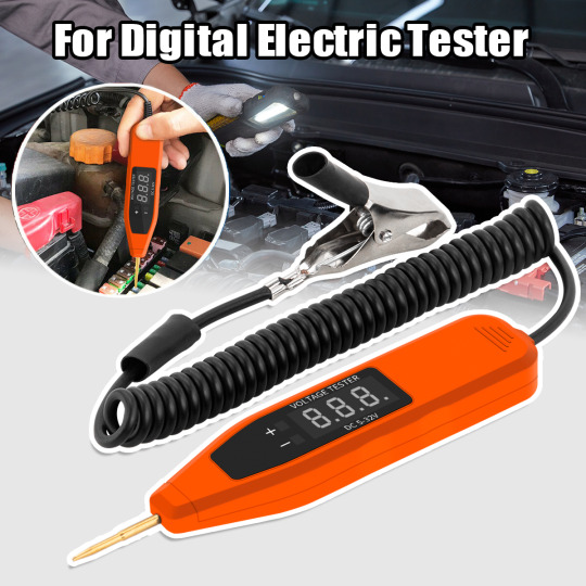
5-32V Vehicle Probe Digital Electrical Circuit Tester Pen
Description Multi-function Car Electric Pen, Specially Designed to Detect the Failure of the Low-voltage Circuit of the Transportation Machinery Description – Clear digital display for accurate voltage readouts,accurate to 0.1 volt – Test light for checking fuses, switches, armatures,distributors and electrical circuits to locate short and open circuits quickly and easily – For use on cars,…
View On WordPress
0 notes
Text

Cable Harness Tester | Digilogic Systems
The cable harness tester has an important role in bringing in the quality and reliability of electrical cable assemblies that are used in many industries, such as aerospace, automotive, defense, and manufacturing. This is one of the most important functions of cable harness assembly as it helps in finding defects, ensuring the connectivity is right, and testing the on-field performance of the harnesses.
A complete turnkey solution for cable harness testing rather would include providing Test Hardware and service support as well. It contains complete services like Test Software development, but it's also customized by the specific purpose of the client's application, such as Hardware Interface.
What is a Cable Harness Tester?
The cable harness testers are to carry out a variety of tests such as continuity checks, insulation resistance measurements, voltage withstand tests, and looking at the messages. This will ensure proper signal transmission.
As a part of the proposal and the Hardware components of the test cable harness, Tester is also an important factor. To achieve a simple interface for the user conducting tests, analyzing the results, generating the reports, and organizing the test data. The software can be tuned to cover various test scenarios, protocols, and standards applicable to particular industrial areas like aerospace-defence and automotive.
Another key element of a full turnkey solution that is typically required for the testing of cable harnesses is customized hardware interfaces. The front end of the software is created such that it is free-flowing with the client's existing systems, machines, and processes. They become the strong suit of data transferring, testing system automation, and their adapting to different networks and connectors.
How does the Diglogic’s cable harness tester work?
The Cable Harness Tester developed by Digilogic Systems is an innovative option tailored to the diverse product testing scene within wire harness manufacturers. Technological breakthrough gives a customer a chance to try a whole turnkey solution. At Test Hardware and Test Software stages, the customer has a possibility of adapting them to their unique application scenario.
Digilogic Systems Cable Harness Tester most importantly consists of both the hardware and software components that are also connected smoothly together. The tester is designed to contain the latest electronics that can detect whether there is damage and does that within a very short time and precise.
Cable harness connections to the tester ensure a successful test process at the starting point. The tester's hardware interfaces are designed to cater to different types of harness configurations being the reason behind the fact that such configurations can work ideally in various applications. The Test Software, developed in adherence with the client's specific needs, starts the whole testing exercise after clicking on it.
What distinguishing qualities make the Digilogic Systems Cable harness tester the best option?
The programmable platform from digilogic systems uses advanced algorithms to execute functions through a cable harness and, subsequently, they respond to driveline behaviour. This testing scheme utilizes a wide range of parameters continuity, insulation resistance, conductor resistance, and others. If the comprehensive assessment of these parameters is done, the possibility of finding a defect, including a short circuit, open circuit, or misconnection, can be done very precisely.
Besides this, the most notable quality of Digilogic's Cable Harness Tester is its intuitive and user-friendly interface. The software provides a user-friendly interface with visualization and evaluation methods for test results. Workers can quickly understand the received data and make appropriate decisions. With this navigation streamlined, the interface becomes productive as it reduces the time for learning and training.
Applications of Cable Harness Tester
Automotive: The cable harness tester is useful in automotive production to check engine wiring, control units, and electronic boards. They are those provisions that promote the integration of communications and threading into motor vehicle technologies together.
Aerospace and Defence: In aerospace applications, wire harness tests are carried out to show the design integrity of aircraft wiring systems, avionics test systems, and mission-critical connections.
Electronics and Telecommunications: The harness testing machines for electronic equipment, telecommunication devices, and industrial systems lie in testing the signal paths and power distribution. They inherit this very function therefore they are responsible for the quality assurance and dependability in different fields of application.
Digilogic System Cable Harness Tester Benefits
Quality Assurance: Cable harness testers play a significant role in ensuring that cable harnesses are high-quality, reliable, and free of defects, thereby saving money on rework or recall.
Time and Cost Savings: Automation in testing covers many aspects like this, which include reducing the time and effort spent on test runs, increasing the effectiveness of testing, and also improving resource disposition, thus leading to higher productivity and cost-effectiveness.
Regulatory Compliance: The possibility of meeting industry standards and regulatory requirements is greatly simplified by the cable harness testers, ensuring the performance of the electrical equipment is compliant with safety, performance, and environmental regulations.
Fault Detection and Diagnostics: The detection of wire faults, component failures, and manufacturing faults at their initial stages has enabled fast corrective measures and, thus, reduced the operating time and improved the system's reliability.
Conclusion:
Digilogic Systems' Cable Harness Tester offers a comprehensive solution for harness testing and cable testing needs. With a focus on providing not just Test Hardware but also developing tailored Test Software and Hardware Interfaces, Digilogic systems ensure that clients receive a fully integrated and customized solution. The Cable Harness Tester is designed with the latest technologies, ensuring speed, accuracy, and user-friendliness while meeting the evolving requirements of wire harness manufacturers. Digilogic's commitment to modern development practices guarantees timely delivery, competitive pricing, and the ability to meet specific client demands, making it a reliable choice for comprehensive cable testing solutions.
Contact us today to discuss your cable harness tester requirements
Website: https://www.digilogicsystems.com/ Phone: Hyderabad: (+91) 40 4547 4601 / 02 / 03 Bengaluru: (+91) 80 4975 6034 Email: [email protected] Location HEAD OFFICE
102, 1st Floor, DSL Abacus Tech Park Beside DSL Virtue Mall, Uppal, Hyderabad, Telangana-500 039, India
BRANCH OFFICE
216, 3rd floor, Zareen Heights, Varthur Road, Nagavarapalya, C. V. Raman Nagar, Bengaluru, Karnataka — 560093.
0 notes