#precisioncabling
Explore tagged Tumblr posts
Visit Tumblr Blog
Explore Tumblr blogs with no restrictions, modern design and the best experience.
Last Seen Tumblr Blogs


Fun Fact
Tumblr was acquired by Yahoo for $1.1B in 2013.
Text
What Impacts Cable Size? Load, Length, and More

When you’re setting up an electrical system, the size of the cable might look like a simple choice at first glance. But it’s actually influenced by several factors that affect how well your installation performs and how safe it is over time. After all, choosing the right cable isn’t just about picking numbers off a datasheet.
To determine the correct cable size, you need to understand how your electrical load, cable length, installation environment, and system type work together. In this article, you get to learn the clear, technical guidance on what impacts cable size, tailored to your residential or commercial projects, while following Australian standards.
Factors That Affect Cable Size
Understanding the main factors influencing cable size helps you choose the right cable for your electrical needs. Some of these factors include the following!
Electrical Load
One of the primary influences on cable size is the electrical load—the current your cable must safely handle. To determine this accurately, you need to perform a proper load calculation. To start, you need to identify the power consumption of your devices or equipment, measured in watts. Then, calculate the current in amps by using one of these formulas, depending on the system:
For Single-Phase AC Systems:
I = P ( V · PF )
For Three-Phase AC Systems:
I = P (√3 · V · PF )
Where:
I = Current in Amps
P = Power in Watts
V = Voltage in volts
PF = Power factor, usually between 0 and 1
For example, a 2400-watt appliance operating on a 240-volt supply draws about 10 amps. The cable you choose must safely carry this current continuously without overheating.
Selecting a cable that’s too small risks overheating, potentially causing insulation damage, fire hazards, or equipment failure. Therefore, the cable’s rated current-carrying capacity must meet or exceed the load current calculated. In addition to that, focus on the continuous load rather than just peak or startup currents, as cables heat up based on sustained current flow over time.
Cable Length and Voltage Drop
The longer the cable length, the more electrical resistance it encounters, which causes voltage drop—a reduction in voltage as electricity travels along the cable.
Voltage drop reduces the voltage available to your devices, potentially causing them to underperform or sustain damage over time. To maintain system reliability and comply with standards, the voltage drop is typically limited to a maximum of 5% of the supply voltage.
For example, a cable carrying a 10-amp load over 10 metres might be fine with a 1.5mm² cross-section, but if the run extends to 40 metres, you would need a larger cable, such as 2.5mm² or more, to keep voltage drop within acceptable limits.
To calculate voltage drop accurately, you can use formulas or online calculators. You can also consult AS/NZS 3008, which provides detailed tables and guidelines for various cable types and loads.
Installation Conditions and Cable Grouping
Where and how you install your cable also affects the size you should use. Installation conditions influence how much heat a cable can safely release. If cables are installed in tight spaces, bundled closely, or surrounded by insulation, heat builds up and lowers the amount of current the cable can safely carry.
For example, running multiple cables in a conduit increases heat, and installing cables under floors or in ceiling spaces with poor ventilation limits cooling. Underground cables face different heat conditions depending on soil type and moisture. In these situations, you need to apply derating factors.
These multipliers, specified in AS/NZS 3008.1.1:2017, reduce the cable’s current rating to account for reduced cooling and increased thermal resistance. Derating applies based on:
Installation method (e.g. buried, clipped, enclosed)
Grouping/bundling of cables
Ambient or soil temperature
Cable spacing
To maintain safety and performance, you often need to select a larger cable size when these conditions apply. A cable sizing calculator simplifies this process by automatically applying the correct derating factors based on your selected installation method, ensuring compliance and reducing manual errors.
Cable Type and Insulation Material
Not all cables with the same conductor size have identical current ratings. The type of insulation material covering the conductor affects how much heat the cable can withstand.
Different insulation types affect how much heat a cable can handle and how it's used:
PVC: Standard insulation for general use, rated up to 75°C continuous.
XLPE: Used in higher-load and solar applications, rated up to 90°C continuous and 250°C short-circuit.
EPR: Flexible and durable, rated up to 90°C. Common in industrial settings.
For solar cables, XLPE or similar high-temperature-rated insulation is typically required to meet performance and durability standards.
Choosing a cable with insulation rated for higher temperatures can allow smaller cable sizes or better performance under harsh conditions. In addition to that, certain applications require cables with extra protection against moisture, UV exposure, or mechanical damage. The right insulation extends cable life and reliability.
Voltage Level and Phase Type (Single vs Three-Phase)
The voltage of your system and whether it uses single-phase or three-phase power significantly impact cable size. In Australia, residential systems usually operate at 230 volts single-phase, while commercial and industrial setups often use 400 volts three-phase.
With three-phase power, the electrical load is divided across three conductors, which lowers the current in each cable. For instance, a 10 kW load on a 230V single-phase supply draws around 43 amps, while the same load on a 400V three-phase system draws only about 14.4 amps per conductor. This difference allows you to use smaller cables in many three-phase installations.
However, knowing how to size cables correctly involves more than just comparing currents. You also need to consider factors like cable length, voltage drop, and environmental conditions. When all elements are properly evaluated, you can select a cable that offers safe performance, long-term reliability, and compliance with Australian electrical standards.
Choose the Right Cable Confidently with CableHero
Selecting the right cable size impacts everything from safety to system efficiency. By considering your electrical load, cable length, installation conditions, cable type, voltage configuration, and future expansion, you can select cables that meet your needs. This also helps ensure your installation complies with regulations.
To make the process easier and more accurate, CableHero’s online cable sizing calculators let you input project-specific details and apply the correct standards automatically. So, discover the tools you need for precise cable sizing, diagram drawing, and conduit calculations, all of which comply with AS3008 and AS3000 standards. For more information, visit our website today!
0 notes
Text
Global Industrial and Electrical Fuses Market Research Report Market Technology, Regional Outlook, Competitive Strategies And Forecast 2021-2026
The Global Industrial and Electrical Fuses Market 2021-2026, which consists of a satisfying and precise framework, such as SWOT inspections, reflects a complete evaluation of the remarkable specialists. The analysis gives a market summary that talks about market circumstance and the significant segments. This Research Report also offers market share analysis, division, income forecasts. The market analysts authoring this report have given in-depth data on driving development drivers, restraints, challenges, trends, and opportunities to offer a complete analysis of the global Industrial and Electrical Fuses market. The market has quick improvement in the current and past years and is going to progress with continuing development in the upcoming years.
The study offers significant measurements available status of makers and offers helpful advice and direction for businesses and individuals interested in the industry. The Industrial and Electrical Fuses market report centers around the monetary advancements and buyer spending patterns crosswise over various regions for the forecast 2021 to 2026. The exploration further uncovers which regions and nation will be leading in the market. The analysis provides the development, analysis and forecast with the ongoing improvements in the Industrial and Electrical Fuses business around the globe. Furthermore, the exceptional profiles of market players will add significance to the report.
Detailed TOC along with also Charts & Tables of Industrial and Electrical Fuses Market Research Report accessible at: https://www.futuristicreports.com/request-sample/100878
Top Important Players:
LiteefuseEatonBelSchneider ElectricSchurterAltechAmphenolBandK PrecisionCal Test ElectronicsGrayhill
The scope of the report expands from market situations to similar valuing between significant players, cost and benefit of the predetermined market regions. The numerical information is sponsored up by factual devices, for example, SWOT analysis, and PESTLE analysis. The measurements are spoken to in graphical configuration for an unmistakable comprehension of statistical data points.
Global Industrial and Electrical Fuses Market is abbreviated as Follows- By Types:
Fast Blow
Medium/Normal Blow
Time Delay/Slow Blow
By Applications:
Construction
Automotive
Industrial
Consumer electronics
Energy
Others
Regional Or Country Level Customization : https://www.futuristicreports.com/customize-request/100878
-Significant Key Points Covered in Industrial and Electrical Fuses Market 2021: 1. Introduction of Industrial and Electrical Fuses Market 2021 with advancement and status. 2. Gathering Technologies involved in the Industrial and Electrical Fuses Market 2021. 3. Analysis of international Industrial and Electrical Fuses key players with Company Profile. 4. Review of WorldWide Industrial and Electrical Fuses 2021 Competence. 5. Keyword Analysis with Status and Competition by Companies and Countries.
-Different inquiries addressed through this research report:
* What will be the market growth rate of Industrial and Electrical Fuses in upcoming years?
* What are the key factors motivating the Industrial and Electrical Fuses?
* Which market trends are causing various segments development?
* Who Are the Global Industrial and Electrical Fuses Key Players?
* What Was Global Market Status?
* What Is Economic Impact On Industrial and Electrical Fuses Market?
Enquire more at: https://www.futuristicreports.com/send-an-enquiry/100878
Media Contact:
Company Name: Futuristic Reports
Email: [email protected]
Visit our website: https://www.futuristicreports.com
Phone: +1 (408) 520 9037
Address: 2066 N. Capitol Ave, Suite 3041
City: San Jose, CA 95132
Country: United States
0 notes
Text
Cable Size and Safety Compliance: What Australian Electricians Must Know

Electricians must ensure that every installation complies with the AS/NZS 3000 Wiring Rules, which set out the safety principles for electrical systems. Truth be told, undersized cables may lead to overheating, energy loss, or even fire, while oversized cables, although safer, can result in unnecessary costs. With accurate sizing, it basically promotes compliance and cost-effective performance in the long run.
So whether you’re working in residential, commercial, or industrial environments, understanding cable sizing manually or with a cable calculator is essential to your daily work. It ensures your installations are accurate, safe, and aligned with Australian standards.
Why Cable Sizing Matters for Compliance and Safety
When you choose the correct cable size, your system functions efficiently and poses fewer risks to users, structures, or connected devices. The Australian Wiring Standards provide the foundation for safe installations. If you don't comply, you risk inspection failures, rework, or hazards like electric shock or fire. Moreover, when a cable is too small for its current, it generates excess heat, gradually damaging insulation and connected components. This can eventually result in equipment failure or fire hazards.
Meanwhile, using larger cables than necessary may appear safer, but it increases material costs and can make routing more difficult. Overall, a well-sized cable supports efficient operation, complies with safety standards, and helps you manage project costs effectively.
Factors That Affect Cable Sizing
You need to evaluate several interrelated factors when determining the correct cable size. These include:
Current Load: The amount of current the cable carries determines its minimum cross-sectional area. Higher loads require larger cables to handle heat safely.
Voltage Drop: Voltage is lost over distance. Clause 3.6.2 of the Wiring Standard states that the voltage drop should not exceed 5% of the nominal voltage.
Cable Length: Longer runs increase resistance. To maintain voltage levels, you need thicker cables.
Insulation and Installation Conditions: How you install a cable affects its ability to dissipate heat. Cables in conduits or thermal insulation retain more heat, reducing current-carrying capacity.
Environmental Temperature: High ambient temperatures reduce a cable’s current capacity. You may need to apply derating factors.
Type of Conductor: Copper and aluminium conductors differ in resistance. Copper is more conductive, so a smaller size may be enough. Meanwhile, aluminium cables usually require larger diameters.
By using a cable calculator, it helps you factor in all these variables efficiently. With a reliable tool, it will provide a recommended cable size that aligns with safety standards and practical installation requirements.
How to Size Cables the Right Way
Begin by collecting accurate information about the installation. You need to know the current load, voltage, phase type, installation method, run length, and environmental factors. With this information, you can either calculate manually or use a cable calculator.
Manual sizing relies on AS/NZS 3008, which provides current-carrying capacities and correction factors for different installation types and materials. You will need to use formulas such as:
For Single-Phase AC Systems: Vd1 = 2 · L · ( RcosΦ + XsinΦ ) · L
For Three-Phase AC Systems: Vd3 = √3 · I · ( RcosΦ + XsinΦ ) · L
Where:
Vd = voltage drop (volts)
I = current (amps)
R = resistance of the cable (ohms per metre)
X = reactance of the cable (ohms per metre)
cosΦ = power factor of the load
L = one-way cable length (metres)
For three-phase systems, you should also consider additional correction factors. Because these calculations can be complex, many electricians now use digital tools.
Manual Cable Sizing vs. Cable Calculators
Manual methods are dependable when performed correctly but take time and demand precision. For instance, you need to consult tables, apply correction factors, and understand electrical theory. Mistakes in interpretation can also lead to undersized or oversized cables.
Meanwhile, a trusted cable calculator can guide you through data input for load type, run length, voltage, and insulation type. The tool then applies the relevant standards and outputs a recommended size. As a result, it saves you time and reduces the risk of calculation errors.
That said, calculators are only as accurate as the data you provide. You still need to understand the principles behind the numbers and verify the result against AS/NZS standards. The calculator can be a helpful tool but not a substitute for professional judgment.
Common Mistakes to Avoid When Sizing Cables
Even experienced electricians can make errors that compromise safety and compliance. One of the most common is underestimating the current load or failing to consider possible future increases. This results in cables that run hot during normal use.
Another oversight involves voltage drop, particularly on long cable runs. Even if the current rating is suitable, a high voltage drop can cause malfunction and inefficiency.
It’s also easy to overlook derating factors. Ignoring ambient temperature, close cable groupings, or incorrect installation types leads to undersized cables. Errors in a cable sizing calculator, like entering the wrong load type or forgetting environmental details, can also affect sizing.
Finally, some electricians neglect to size earth conductors correctly. Earth cables must handle fault currents long enough for protective devices to operate within time limits.
Make Every Wiring Installation Compliant and Efficient
Following the Australian Wiring Standard and applying correct cable sizing supports long-lasting, efficient, and safe installations. When you use a cable calculator wisely and continue refining your knowledge, you reduce the risk of failure and ensure that every job meets the required standard.
With CableHero's innovative online calculators, it takes this further by simplifying complex calculations. We provide reliable calculations tailored to your specific project needs, making compliance faster and more accessible. For more information, visit our website today!
0 notes
Text
How to Figure Out Voltage Drop in Long-Distance Circuits

Voltage drop is a critical yet often overlooked challenge in electrical engineering, particularly for circuits spanning extended distances. So if you’re designing power distribution networks, renewable energy systems, or industrial installations, understanding how to figure out voltage drop effectively ensures efficiency, safety, and compliance with standards like AS/NZS 3000.
This article dives into the nuances of the circumstance, especially in long-distance applications, offering actionable methods to calculate and mitigate losses. Additonally, it emphasises the role of modern tools in simplifying the process.
Why Long-Distance Circuits Are Vulnerable to Voltage Drop
In electrical systems, a voltage drop occurs as energy is lost due to resistance in conductors. While negligible in short runs, this loss becomes pronounced over long distances, where resistance accumulates proportionally with cable length.
For example, a 500-meter underground feeder cable in a solar farm may experience a significant voltage drop, reducing the efficiency of energy transfer to inverters.
Standards such as AS/NZS 3000 Clause 3.6 impose strict limits (e.g., 5% for general circuits) to prevent operational risks like motor overheating or dimmed lighting. Engineers should prioritise precise calculations to balance performance and regulatory compliance.
Key Variables Impacting Voltage Drop
The process on how to figure out voltage drops in electrical systems is influenced by three primary categories of variables. These include conductor characteristics, operational parameters, and circuit configuration. Conductor material (e.g., copper vs. aluminium) and the cross-sectional area directly determine resistance.
On the other hand, operational factors like current load and ambient temperature amplify resistive losses. In addition to that, system design choices, whether a single-phase or three-phase configuration. Installation methods also play a critical role in balancing efficiency and compliance with industry standards.
Understanding these variables is essential for optimising cable selection and mitigating energy losses. These key variables include:
Conductor Characteristics
Material: Copper’s lower resistivity value of 1.72 × 10⁻⁸ Ω·m outperforms aluminum resistivity value of 2.82 × 10⁻⁸ Ω·m, making it ideal for minimising losses.
Cross-Sectional Area: Doubling a cable’s cross-sectional area significantly reduces its resistance, as resistance is inversely proportional to the area (R ∝ 1/A); for example, increasing from 4 mm² to 10 mm² lowers resistance and thus reduces voltage drop.
Operational Parameters
Current Load: High-current circuits (e.g., industrial motors) demand larger conductors to offset resistive losses.
Temperature: Resistance increases with heat due to the positive temperature coefficient of copper; for example, at 30°C, resistance is about 10% higher than at 20°C, following the relation R=R0[1+α(T−T0)]R = R_0 [1 + \alpha(T - T_0)]R=R0[1+α(T−T0)], where α\alphaα is copper’s temperature coefficient (~0.00393/°C).
Circuit Configuration
Single- vs. Three-Phase: Three-phase systems leverage √3 in calculations, often yielding lower losses for equivalent power transfer.
Installation Method: Buried cables experience higher thermal resistance than aerial lines, which affects derating factors. Other factors such as the grouping of cables, depth of burial, soil thermal resistivity, and proximity to heat sources also contribute to reduced current-carrying capacity.
Step-by-Step Voltage Drop Calculation
To determine voltage drop manually, apply the following equations for voltage drop, tailored to the circuit type.
Where:
I = current (amperes)
L = one-way cable length (meters)
R = conductor resistance (ohms per kilometer)
Single-Phase Systems
Three-Phase Systems

Advanced Techniques for Long-Distance Optimisation
Optimising long-distance electrical circuits requires advanced strategies to minimise voltage drop and ensure system efficiency. Key approaches include increasing system voltage, adjusting conductor sizing, and leveraging online voltage drop calculators.
Increase System VoltageTransitioning from 230 V single-phase to 400 V three-phase slashes current by 43%, reducing resistive losses.
Conductor Sizing AdjustmentsUse AS/NZS 3008 tables to select cables based on current-carrying capacity and voltage drop. For instance, a 10 mm² copper cable reduces voltage drop by 60% compared to 6 mm² in high-load scenarios.
Leverage Online Voltage Drop CalculatorsModern tools like CableHero eliminate manual errors by automating complex calculations:
Input Parameters: Conductor type, length, load, temperature, and installation method.
Output: Voltage drop percentage, recommended cable size, and compliance status with AS/NZS 3000.
These tools integrate correction factors for ambient temperature and installation methods, ensuring precise results tailored to real-world conditions.
By transitioning to higher voltages, engineers can significantly reduce current and resistive losses, while proper cable selection using AS/NZS 3008 tables ensures compliance with industry standards.
Additionally, modern voltage drop calculators simplify complex computations, integrating real-world factors like temperature and installation methods for precise and reliable results.
Common Mistakes and How to Avoid Them
Even with careful planning, errors in voltage drop calculations can lead to inefficiencies, non-compliance, or system failures. To guide you on the common mistakes, take a look at a few of these issues!
Ignoring Temperature Effects
Fix: Apply correction factors from AS/NZS 3008 for ambient temperatures above 30°C. The standard provides two sets of temperature correction factors depending on the installation method—cables installed in air or on a slab use Table 27(1), while directly buried cables use Table 27(2). These adjustments help ensure safe current-carrying capacity under varying environmental conditions.
Overlooking Harmonic Currents
Fix: Use THD-adjusted load values in voltage drop calculations when dealing with non-linear loads (e.g., variable frequency drives). These adjusted values account for the additional current stress caused by harmonic distortion, ensuring more accurate results and preventing underestimation of voltage drop in systems with significant harmonic content.
Misapplying Formulas
Fix: Double-check whether the system is single-phase or three-phase, as each requires a different voltage drop formula. For single-phase systems, use Vd=2IR, accounting for the full loop (active and neutral conductors), while for three-phase systems, use Vd=√3IR, reflecting the phase-to-phase configuration. Ensuring the correct formula and corresponding voltage value (phase-to-neutral vs. phase-to-phase) is crucial for accurate calculations.
Manual Calculation Errors
Fix: Use online voltage drop calculators to cross-verify results and ensure compliance with industry standards.
Fortunately, these issues can be avoided by applying correction factors from AS/NZS 3008, using THD-adjusted load values, verifying formulas for circuit type, and leveraging online voltage drop calculators to cross-check results. Addressing these pitfalls ensures accurate designs and compliance with AS/NZS 3000 standards.
Achieve Advanced Voltage Drop Calculations with CableHero!
Mastering how to figure out voltage drops in long-distance circuits requires a blend of theoretical knowledge and practical tools. By leveraging precise equations, adhering to AS/NZS 3000 standards, and utilising advanced calculators, engineers can design systems that minimise energy loss and maximise reliability.
Online calculator tools like CableHero streamline calculations and reduce human error, making them indispensable for ensuring compliance and operational efficiency in even the most demanding electrical installations.
0 notes
Text
Overview of AS/NZS3000 Wiring Rules for Residential Installations
Understanding AS3000 wiring rules is important for electricians, builders, and homeowners. It outlines best practices for electrical installations, including wiring methods, load calculations, and safety measures.
That said, adhering to these guidelines minimises risks and prevents electrical hazards. This article focuses on the key aspects of AS 3000 for residential installations and explains their application and significance.
What Are the AS3000 Wiring Rules?
The AS/NZS 3000 governs electrical installations in Australia and New Zealand. This standard aims to enhance safety and reliability in electrical systems. The current 2018 version includes updates that address recent technological advancements and safety practices.
These updates introduce provisions for renewable energy systems, increased safety measures, and improved guidelines for residential installations.
Compliance with AS 3000 is mandatory for electrical work in both countries. The rules outline mandatory requirements that electricians must follow and recommendations that serve as best practices. Ultimately, they protect people and property by minimising electrical hazards, preventing electrical shocks, and reducing fire risks.
Key Sections of AS 3000 Relevant to Homes
Several sections of AS 3000 specifically address residential properties.
Section 1 covers the scope, application, and fundamental principles, establishing the framework for safe home electrical installations.
Section 2 discusses the general arrangement, control, and protection of electrical systems, focusing on ensuring safety through proper design and equipment.
Section 3 outlines the selection and installation of wiring systems and details acceptable practices for different home environments.
Section 4 addresses the selection and installation of appliances and accessories, ensuring compatibility and safety.
Section 8 highlights requirements for special electrical installations, such as swimming pools and outdoor lighting, which require additional safety considerations.
Safety Requirements Every Homeowner Should Know
Many homeowners overlook the role of wiring standards in day-to-day safety. Knowing the specific safety requirements in AS 3000 helps identify potential risks before they become serious problems.
Power Circuit Requirements
The AS3000 wiring rules indicate that each power circuit in residential installations must not exceed the maximum number of power outlets to avoid overloading. While there is no strict limit on the number of power outlets per circuit, a common industry guideline allows up to eight to ten double general-purpose outlets (GPOs) on a 10 A circuit.
However, the actual number should be based on proper load calculation, appropriate cable sizing, and the use of suitable protection devices. This is highlighted in Clause 2.6.2.1 to ensure cables carry the expected load safely.
Moreover, Clause 4.7.1 mentions that appliances such as ovens, air conditioners, and electric hot water systems should be on dedicated circuits to prevent overloading. Due to moisture and high-demand appliances, kitchens and laundries should also follow additional rules.
These include using Residual Current Devices (RCDs), installing separate circuits for dishwashers and washing machines, and ensuring appropriate Ingress Protection (IP)-rated outlets are used in areas exposed to water.
Lighting Circuit Requirements
A single lighting circuit should not exceed a total load that compromises safety or performance. While the rules do not directly limit the number of light points, electricians must consider total current load and cable capacity and voltage drop on the last fixture when designing the circuit.
Furthermore, the cable size must match the load and circuit length to prevent overheating or voltage drop. Outdoor lighting requires weatherproof fittings, correct IP ratings and suitable protection against moisture and mechanical damage.
Bathrooms and other wet areas also follow strict light placement and protection rules, especially near showers and bathtubs. For example, the area directly above the bath or shower, up to 2.5 metres high, should only have an IPX4-rated or higher light fitting. Additionally, all light fixtures should also be protected by an RCD.
Wet Areas and Special Locations
The AS 3000 has special requirements for wet areas and special locations due to the increased risk of electrical shock. Outdoor areas, such as gardens, pool zones, decks, and verandas, require weatherproof equipment with specific IP ratings. For example, pool zones require IPX5-rated fittings to withstand water jets.
Electrical equipment installed outdoors must also be protected by RCDs, which are the Australian standard, or by GFCIs (Ground Fault Circuit Interrupters) in other regions. These devices help reduce the risk of electric shock in damp or exposed environments.
In addition, the rules explain IP ratings to classify how well electrical enclosures resist water and solid objects. An IP44 rating, for example, protects against splashing water and small particles, making it suitable for covered outdoor spaces.
Common Compliance Issues
Several common issues can lead to non-compliance with AS 3000, especially in older or modified homes. For instance, outdated switchboards often lack proper circuit breakers or RCD protection, which increases the risk of shock and fire. Many homes also don't have enough RCDs, leaving circuits unprotected and violating current safety requirements.
With that said, many DIY electrical modifications often ignore mandatory safety measures or use improper materials, resulting in non-compliance. Moreover, inadequate grounding systems create serious safety hazards during faults or lightning strikes.
Another common oversight is failing to calculate voltage drop on long cable runs, which leads to poor performance and possible overheating. As per AS/NS 3000 Clause 3.6.2, the maximum allowable voltage drop from the point of supply to any outlet or appliance is 5% to ensure efficient and safe operation.
To prevent poor performance or overheating, look for frequent breaker trips, flickering lights, discoloured outlets, or outdated equipment. Lastly, a licensed electrician should conduct a full inspection to identify potential issues in your home.
Importance of Voltage Drop Calculation
Voltage drop refers to the reduction in voltage that occurs as electrical current flows through conductors. It's important because excessive voltage drop can lead to inefficient operation of electrical devices and potential equipment damage.
To calculate voltage drops accurately, you can use a voltage drop calculator. This tool considers factors such as circuit length, conductor size, and current load, as well as factors attributed to the environmental and installation method. Common scenarios where voltage drop becomes problematic include long cable runs to outdoor lighting or power outlets.
Practical solutions for addressing voltage drop issues include using larger-diameter conductors, shortening cable runs by re-routing and implementing additional circuits to balance the load.
Ensure Safe Electrical Installations with CableHero
The AS3000 wiring rules provide clear guidance on safety, efficiency, and compliance to ensure reliable electrical systems while minimising risks. Adhering to these rules helps electricians and homeowners create safe environments that protect people and property.
Using CableHero's calculators, such as voltage drop, cable sizing, and overcurrent protection sizing, further ensures requirement compliance. These tools help users make informed decisions by automatically calculating safe and compliant values based on inputs like circuit length, conductor size, and current load. For more information, visit our website today!
0 notes
Text
Why Every Electrical Engineer Should Use Cable Size Calculators

Cable calculators are indispensable tools for electrical engineers, enabling precise calculations and ensuring safe and efficient installations. While voltage drop calculations remain crucial for circuit design, integrating cable calculators into workflows enhances accuracy and compliance with industry standards.
Importance of Cable Calculators in Electrical Engineering
Modern cable calculators offer different benefits to guarantee accuracy and efficiency. With these tools, engineering professionals can reduce mistakes due to wrong resistance values and ratios. Moreover, they have internal validation to prevent common errors.
Many of these tools are available online, enabling engineers to save time, compare multiple design scenarios, and achieve optimal outcomes based on load requirements and environmental conditions..
Additionally, these tools streamline the process of determining the correct cable size for various applications by addressing the following key parameters:
Voltage drop limits to minimise energy losses.
Ambient temperature and installation methods affecting the cable capacity.
Compliance with standards like AS/NZS 3008 and AS3000 wiring rules.
Overall, these advanced cable calculators ensure that engineers can design systems that are both safe and efficient while adhering to industry regulations.
Key Features of Quality Cable Calculators
One of the powerful features of cable size calculators is that they have the following advanced features:
Value added cable sizing calculation
Voltage drop and voltage rise analysis
Fault loop impedance calculation
Overcurrent protection device sizing calculation
Short circuit current calculation
Report ready for client-use
PDF reports
Another bonus is that these tools are designed to incorporate Australian standards like AS/NZS 3008 and AS3000 wiring rules.
AS/NZS 3000 Compliance in Cable Calculator Applications
In Australia, compliance with AS/NZS 3000 wiring regulations is mandatory for safe and efficient electrical installations. Clause 3.6.2 of the standard states that ”voltage drop must not exceed 5%“.
Under normal service conditions, the voltage at the terminals of any power-consuming electrical equipment shall be not less than the lower limit specified in the relevant electrical equipment Standard.
Where the electrical equipment concerned is not covered by a Standard, the voltage at the terminals shall be such as not to impair the safe functioning of the electrical equipment.
The cross-sectional area of every current-carrying conductor shall be such that the voltage drop between the point of supply for the low voltage electrical installation and any point in that electrical installation does not exceed 5% of the nominal voltage at the point of supply.
Cable calculators simplify compliance by accurately determining allowable voltage drop and helping select cable sizes that meet or exceed this requirement.
How Cable Calculators Ensure Compliance
Cable size calculators integrate features like correction factors for ambient temperature, installation methods, and conductor material. These tools help ensure compliance with industry standards.
One practical application of online cable calculators is in residential solar installations, where accurate cable sizing is essential to minimise power loss and ensure efficiency. For instance, when connecting solar panels to an inverter or battery bank, these calculators determine the correct cable size by factoring in current capacity, voltage drop, and cable length, ensuring safe operation and compliance with AS/NZS 3008 standards.
In industrial settings, online cable calculators are equally valuable for designing power distribution systems. For example, when selecting cables for a 400V three-phase system over long distances, these tools use voltage drop equations and correction factors to recommend the optimal cable size. This ensures compliance with AS3000 wiring rules while maintaining safety and efficiency in the installation.
When to Double-Check Your Cable Calculators
While cable calculators are convenient, they aren't error-proof. Thus, it is advisable to always verify results by factoring in actual conditions prior to finalising any electrical design or commencing installation.
That said, it’s best that you manually verify the results in the following scenarios when:
High-Current Industrial Installations: Tools may not account for dynamic loads or harmonic distortions in heavy machinery. For example, a 150 A motor with variable frequency drives (VFDs) introduces harmonics, altering the effective current. Recalculate using adjusted loads and harmonics analysis.
Long-Distance Power Transmission: Calculators might underestimate voltage drop over extended distances for solar farms or remote substations. Manually verify conductor size, material resistivity, and load profiles to ensure energy losses remain within the limits.
Mixed Installation Environments: When cables run through different routes (e.g., underground conduits transitioning to overhead trays), calculators may not adjust for varying thermal or mechanical stresses. Reassess derating factors, maximum/minimum bending radius, and support spacing to prevent insulation damage.
Ensure Electrical Safety & Compliance with CableHero
Online cable calculators offer engineers and electricians several benefits. These tools are engineered for compliance with AS/NZS 3000 and AS/NZS 3008, eliminating guesswork and reducing risk of overloads or short circuits.
Companies like CableHero specialise in these tools to make the process more convenient for electrical professionals. CableHero follows the Clause 4.5 method from AS/NZS 3008.1.1:2017, which determines voltage drop using the load’s power factor. This provides a more precise result than simplified methods.
CableHero's Voltage Drop Method: Based on AS/NZS 3008 Clause 4.5
CableHero follows the Clause 4.5 method from AS/NZS 3008.1.1:2017, which determines voltage drop using the load’s power factor. This provides a more precise result than simplified methods.
The voltage drop is calculated as:
Single-phase systems:Vd = IL × 2 × (Rc × cosθ + Xc × sinθ)
Three-phase systems:Vd = IL × √3 × (Rc × cosθ + Xc × sinθ)
Where:
IL = load current
Rc = AC resistance of the cable
Xc = cable reactance
θ = phase angle of the load’s power factor
This method ensures accurate voltage drop values even when the power factor differs from 0.8 lagging — a common limitation in simplified tables.
Single-phase:Vd = IL × 2 × (Rc × cos(θ) + Xc × sin(θ))
Three-phase:Vd = IL × √3 × (Rc × cos(θ) + Xc × sin(θ))
Where:
Vd = Voltage drop
IL = Load current
Rc = Cable AC resistance
Xc = Cable reactance
θ = Load power factor angle
Cable Hero’s online cable size calculators and cable calculation tables instantly calculate voltage drops and rises, integrate Australian wiring standards, and generate reports ready for client-use. So what are you waiting for? Optimise your electrical design with precision calculations by partnering with us today!
Frequently Asked Questions
If you’re an electrical professional looking into these products, here are a few commonly asked questions you might have.
What are online cable calculation tools?
These are web-based applications, used by engineers to help identify the right cable size for an electrical project. They are used for their accuracy and efficiency to speed up the job.
How to calculate the bending radius of a cable?
To calculate the minimum bend radius, you can use the formula Cable Outer Diameter x Cable Multiplier. But to make matters easier, you can use online tools that help ensure accuracy and efficiency or check the cable datasheet.
0 notes
Text
How to Determine Voltage Drop in Extended Cable Runs and High-Load Applications

Voltage drop is inherent in all electrical systems. In fact, its impact becomes more pronounced in extended cable runs and high-load applications. Excessive voltage drop can lead to inefficient system performance, overheating conductors, malfunctioning connected equipment, and, in severe cases, non-compliance with electrical safety standards.
That said, knowing how to determine voltage drop is important for installations involving long distances or substantial current demand. This article explains the regulatory standards and practical design considerations of this electrical issue.
Fundamental Concepts of Voltage Drop
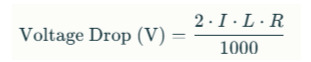
Voltage drop is primarily governed by the conductor's resistance and reactance, the magnitude of current and the length of the run. In simple terms, it is calculated using this specific formula:
Voltage Drop single phase (V) = Current (I) × Resistance x the (L) Cable Length
In more complex three-phase systems or those involving inductive loads, impedance (including reactance) and power factor must also be considered. That said, minimising voltage drop is important for system efficiency and preventing excessive losses.
In addition, voltage drop must be assessed following AS NZS 3000, which specifies a maximum allowable voltage drop of 5% for final subcircuits to ensure operational safety and performance.
Additionally, AS/NZS 3008 provides the necessary resistance for various conductor types, sizes, and installation conditions, forming the basis for accurate voltage drop calculations.
Cable Selection Considerations
Read more below to understand how cable size, material, and installation conditions affect voltage drop and compliance with AS/NZS standards.
Impact of Cable Size and Material
The resistance of a conductor is inversely proportional to its cross-sectional area as part of how to determine voltage drop. Larger conductors exhibit lower resistance, thereby reducing voltage drop. In extended runs, upsizing the conductor is a commonly adopted mitigation strategy.
The conductor material also plays a role. For instance, copper has a lower resistivity than aluminium, making it more effective at reducing voltage drop over long distances. However, aluminium is often selected for cost or weight considerations, requiring careful compensation through increased sizing.
Environmental and Installation Conditions
The installation environment directly influences conductor performance. As detailed in AS/NZS 3008, derating factors must be applied for ambient temperature, cable grouping, and installation method (e.g., buried, conduit, free air). These factors affect the conductor’s effective resistance and, subsequently, the total voltage drop in the system.
High-Load Scenarios and Mitigation Techniques
With the following scenarios and techniques, learn how to identify high-load conditions and apply targeted strategies to effectively reduce voltage drop.
Identifying High-Load Conditions
High-load applications are typically characterised by continuous current flow or substantial startup inrush currents. Examples include industrial machinery with high-duty cycles, HVAC systems with large compressors and electric vehicle charging stations operating at maximum output.
Such conditions elevate the potential for voltage drop and require more rigorous cable and protective device selection, which contributes to how to determine voltage drop.
Strategies to Minimise Voltage Drop
When faced with high-load and long-distance requirements, several design strategies can be applied:
Using parallel conductors to divide the load and reduce individual cable resistance
Minimising cable length wherever possible through layout optimisation
Selecting larger conductors to compensate for extended runs
Choosing low-resistance cable types, especially in aluminium installations where additional size is necessary
These measures reduce voltage drop and ensure circuits remain within allowable performance margins.
Use of Online Tools for Compliance and Accuracy
Many tools, such as a voltage drop calculator from CableHero, can support accurate and standards-compliant design. It incorporates calculation methods based on AS NZS 3000 and AS NZS 3008. The tool factors in current, cable type, material, installation method, circuit length, and power factor offer a precise and compliant voltage drop estimate for single-phase and three-phase systems.
The tool automatically applies the correct correction factors and recommends appropriate conductor sizes for high-load or extended cable run applications. This level of automation ensures alignment with regulatory requirements while improving design reliability.
Common Design Challenges and Avoidance Tips
Several recurring issues can compromise voltage drop calculations, such as:
Incorrect resistance values: Using nominal values instead of corrected figures for installation conditions can skew results
Omitting environmental factors: Neglecting temperature or grouping adjustments can lead to under-sizing
Cost-driven under-sizing: Reducing conductor size to save on material costs may cause non-compliance or equipment failure
To avoid these issues, designers should consistently refer to AS/NZS standards, apply all relevant correction factors, and verify calculations using a validated tool.
Achieve Advanced Voltage Drop Calculations with CableHero!
Learning how to accurately determine voltage drop in extended cable runs and high-load applications ensures the safety, reliability, and compliance of electrical installations. That said, applying the correct calculation methods, considering environmental influences, and adhering to AS NZS 3000 and AS/NZS 3008 standards is essential for achieving optimal performance.
For professionals seeking accurate results and greater design confidence, tools like the CableHero voltage drop calculator provide a practical, standards-aligned solution for simple and complex installations.
To learn more about our online calculator, visit the CableHero website today!
#cablehero#electricaldesign#precisioncabling#smartwiring#safeconnections#as3008#as3000#voltagedropcalculator
1 note
·
View note