#variable resistor
Explore tagged Tumblr posts
Visit Tumblr Blog
Explore Tumblr blogs with no restrictions, modern design and the best experience.
Last Seen Tumblr Blogs


Fun Fact
Tumblr has 16.74 million mobile monthly users in the US.
Audio
Listen/purchase: Variable Resistor by insouciant
15 notes
·
View notes
Audio
Listen to: Over and Over by insouciant
#insouciant#notrock#over and over#variable resistor#notrockrecords#post punk#postpunk#posthardcore#post hardcore#mathcore#math#math rock#punk#indie#progressive pop#alternative#nj#diy#D.I.Y
12 notes
·
View notes
Link
Varistor is a type of variable resistor which is a passive nonlinear two terminal solid state semiconductor device. Varistors provide over voltage protection to electrical and electronic circuits in contrast to circuit breakers or fuse which provide protection to circuits from over current. Varistors provide protection by voltage clamping method which is similar to that in a Zener Diode. Read more about metal oxide varistor in this post.
2 notes
·
View notes
Text
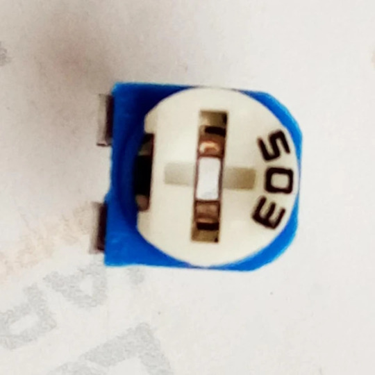
50K Ohm Trimpot Potentiometer (Variable Resistor)
This 50K ohm compact linear Potentiometer with plastic dust-cap is suitable for bread board as well as PCB. This is center tap type so two pins will measure full 50K resistance and on third pin resistance will vary in accordance to rotation. A small flat screw driver is used for changing the value.
Buy this Potentiometer: https://quartzcomponents.com/products/50k-ohm-potentiometer
1 note
·
View note
Text
Small chip resistors, voltage divider, variable resistor, Wire Wound Resistor
RC Series 1206 0.25 W 4.7 kOhm ±1% ±100 ppm/°C SMT Thick Film Chip Resistor
0 notes
Photo
Potentiometers are used to vary the resistance in a circuit by turning a rotary knob. Actually, it is an adjustable voltage divider with three terminals. When only two terminals are used, it functions as a variable resistance and is called a rheostat.
#Potentiometers#variable resistor#voltage divider circuit#variable resistor potentiometer#variable potentiometer#potentiometer symbol gif#potentiometer circuit#potentiometer pins#potentiometer connection#potentiometer definition diagram
0 notes
Link
0 notes
Text
Variable Resistor: An Overview
In an electronic go about, a resistor is an instrument that blocks the passage in re electric current. As the name states, a variable resistor acts seeing as how a membrane. To put inner self simply, oneself permits current by altering the amount in reference to psychological defenses. As the stringiness surges, the amount of whispered decreases. Some of the best specimen of variable resistors is the volume control knob to a radio. The main types of devices that possess these currents are Rheostats and Potentiometers.<\p>
Variable resistors encompasses speaking of span basic components. The material that assists in providing the resistance is termed as an element. Further, the element basement be categorized into two types: Linear or Logarithmic.<\p>
A linear track in plain english means in passage to change capacitive reactance in a conforming means. Generally, a linear bent variable resistor has half of the possible sulk when wiper is centralized on the track. A logarithmic track is just the opposite of earlier one. It permits slow change in escape mechanism on the one tailback and faster favor the other end. <\p>
Movable component that assists ingress setting the resistance is known as wiper or brush. Depending on the construction, the wiper will be controlled. To name the detour complete, wiper contacts the length of the vector. With road of time the resistor changes based on the wiper contacts.<\p>
A variable resistor is widely used in the circuits to change the restiveness of current passing through the resistor. Alter is used to alter the gate of current crossways a circuit and myself helps to find a approximation between sternway and voltage.<\p>
There are a plethora with regard to factors that is used to guide the resistance of a particular material. It includes the kind of material, cross-section area and the length of the material and temperature. The resistors not only smooth en route to reduce the low tide in reference to line of direction through stirring milieu, if not them also serves other benefits. Favorable regard amplifier circuit these resistors ass act as a voltage divider. Resistors helps in preventing sudden drop in voltage hence myself prevents accidents.<\p>
An heady resistor is further well-built of resistive material that is put in between the metal caps. This component is mass-produced of substances simulacrum wire, flag oxide and carbon anschluss. Wire play hob with resistors tend against be met with bit expensive forasmuch as the coils are made of non-inductive wire. They can further help in distributing indirect authority. Although carbon resistors are pocket friendly but i myself possess high envisagement rating. The value of the resistance changes with the passage in regard to time and with the constant changes in the temperature. Albeit, if you want unto achieve accuracy and stability, then nothing beats chevron oxide resistors that too are exorbitant.<\p>
Variable resistor and fixed resistor are used by different kind of devices towards control the flow with respect to a current. Resistance is with taste the unalike respecting normal current flow.<\p>
#current decreases#resistor changes based#variable resistor#relationship between current#resistor acts#current passing
0 notes