
A Leading Huawei Optical Transmission Network Supplier
Don't wanna be here? Send us removal request.
Statistics
We looked inside some of the posts by thunderlinkcom and here's what we found interesting.
Average Info
Notes Per Post
0
Likes Per Post
0
Reblog Per Post
0
Reply Per Post
0
Time Between Posts
1 month
Number of Posts By Type
Text
17
Last Seen Tumblr Blogs


Fun Fact
12.7% of mobile users access Tumblr.
Text
Which command via CLI to check the voltage on the Huawei MA5800-X15 olt sources?
With which command via CLI can I check the voltage on the Huawei MA5800-X15 olt sources?
display power run info The prerequisite is that the OLT can identify the EMU module.
Also, you can try using this:
huawei#display power detail 0 { <cr>||<K> }: Command: display power detail 0 ------------------------------ Power: 415.00 Watt Current: 7757 mA Voltage: 53.50 V SavedPower: 0.00 Watt ------------------------------ Note: Indicates the real-time power
0 notes
Text
Differences Between Control Boards of Huawei MA5616
Control boards supported by the MA5616 chassis include H831CCUB, H831CCUC and H831CCUE.
We list the differences between control boards.
Supported Daughter Board
H831CCUB
Upstream daughter board:
GP1A
GE1A
Voice daughter board:
ASDA
ASDC
ASDM
H831CCUC
Upstream daughter board:
UP2A
UP2C
XP1A
Voice daughter board:
ASDA
ASDC
ASDM
H831CCUE
Upstream daughter board:
UP2A
UP2C
XP1A
Voice daughter board:
ASDA
ASDC
ASDM
Port on the Front Panel (on the Bottom Plate)
H831CCUB
CONSOLE
ESC
ETH
ALARM
GE0
H831CCUC
CON/ESC
ETH
CLK/TOD
ALARM
GE
H831CCUE
CON/ESC
ETH
CLK/TOD
ALARM
GE
Upstream Port (on the Daughter Board)
H831CCUB
When the GP1A daughter board is configured:
GE0 (SFP port)
PON (SFF port)
When the GE1A daughter board is configured:
GE0 (SFP port)
GE1 (SFP port)
H831CCUC
When the UP2A or UP2C daughter board is configured:
0 (SFP port)
1 (SFP port)
When the XP1A daughter board is configured: 10G GPON (SFP port)
H831CCUE
When the UP2A or UP2C daughter board is configured:
0 (SFP port)
1 (SFP port)
When the XP1A daughter board is configured: 10G GPON (SFP port)
Please note, different control boards for the MA5616 chassis support different service boards.
0 notes
Text
S5720-52P-PWR-LI-AC - Rebooting-Issue
If the switch S5720-52P-PWR-LI-AC does not have a management interface, connect the network cable to the first interface. If the first interface of a switch is a combo interface, ensure that the combo interface works in electrical mode.
1. Upgrading the System Software Through the Network Interface
Step 1: Enter the BootLoad menu.
When the switch is starting, the following information is displayed:
Press Ctrl+B or Ctrl+E to enter BootLoad menu: 2
Press Ctrl+B before the countdown timer expires, and then enter the password. In V002R019 and earlier versions, the default Bootload password is [email protected]. In V002R020 and later versions, the Bootload password is not configured by default. Then the BootLoad menu is displayed. The following information is displayed: BootLoad Menu 1. Boot with default mode 2. Enter serial submenu 3. Enter startup submenu 4. Enter ethernet submenu 5. Enter filesystem submenu 6. Enter password submenu 7. Clear password for console user 8. Reboot (Press Ctrl+E to enter diag menu) Enter your choice(1-8):
Step 2. Select 4. Enter ethernet submenu. The following information is displayed: ETHERNET SUBMENU 1. Update BootLoad system 2. Download file to Flash through ethernet interface 3. Upload Configuration file to Ftp through ethernet interface 4. Modify ethernet interface boot parameter 5. Return to main menu Enter your choice(1-5):
Step 3. Modify the parameters of the network interface.
Select 4. Modify ethernet interface boot parameter. The following information is displayed: BOOTLINE SUBMENU 1. Set TFTP protocol parameters 2. Set FTP protocol parameters 3. Return to ethernet menu
Select TFTP or FTP as required.
For example, after you select 2. Set FTP protocol parameters, the following information is displayed and cannot be deleted. New configuration automatically overwrites the old configuration.
Note:
If the TFTP protocol is used, you do not need to enter the user name and password.'.' = clear field; '-' = go to previous field; ^D = quit Load File name : S6730-H-V200R021C00.cc Switch IP address : 192.168.1.15 192.168.0.1 Server IP address : 192.168.1.40 192.168.0.2 FTP User Name : huawei user FTP User Password :
The fields are described as follows:
Load File name: file name of the startup file to be loaded
Switch IP address: switch IP address (the mask is optional)
Server IP address: server IP address
FTP User Name: FTP user name
FTP User Password: FTP password
Step 4 Download the system software.
After network interface parameters are modified, select 3. Return to ethernet menu to return to the Ethernet submenu. Connect a cable to the management interface of the switch. If the switch does not have a management interface, connect a cable to port 1 on the front panel. Then select 2. Download file to Flash through ethernet interface to load the file. The following information is displayed:Use ftp to download file : S6730-H-V200R021C00.cc , please wait for a moment...... Successfully download S6730-H-V200R021C00.cc
After the upgrade file is transferred, select 5. Return to main menu to return to the BootLoad menu.
----End
2 Specifying the System Software to Be Loaded for Starting the Switch
PurposeTo specify the system software to be loaded for starting the switchImpactServices are interrupted when you are specifying the system software and the switch is restarting.PrerequisitesThe system software to be specified has been downloaded to the flash memory.
Specify the system software that is loaded when the switch starts.
Step 1 Enter the BootLoad menu and select 3. Enter startup submenu to enter the startup submenu. The following information is displayed: Startup Configuration Submenu 1. Display startup configuration 2. Modify startup configuration 3. Return to main menu Enter your choice(1-3):
Step 2 Select 2. Modify startup configuration to set the startup mode of the S6730-H, system software, configuration file, and patch file. The following information is displayed:Note: startup file field can not be cleared '.'=clear field; '^D'=quit; Enter=use current configuration startup type(1: Flash) current: 1 new : 1 Flash startup file (can not be cleared) current: S6730-H-V200R020C10SPC500.cc new : S6730-H-V200R021C00.cc saved-configuration file current: vrpcfg.zip new : vrpcfgnew.zip patch package current: S6730-H-v200r011sph001.pat new : S6730-H-V200R021C00SPH001.pat
Table Description of the displayed informationFieldPrecautionsstartup type
Startup mode:
1: The system software is loaded from the flash memory.Flash startup fileSystem software loaded during the startup. If the system software is loaded from the server, you do not need to set the field.saved-configuration fileConfiguration file loaded during startup.patch packagePatch file loaded during startup.currentFile that is currently loaded.newFile to be loaded during the next startup. Startup Configuration Submenu 1. Display startup configuration 2. Modify startup configuration 3. Return to main menu Enter your choice(1-3):
Step 3 After entering the startup information, select 3. Return to main menu to return to the BootLoad menu. BootLoad Menu 1. Boot with default mode 2. Enter serial submenu 3. Enter startup submenu 4. Enter ethernet submenu 5. Enter filesystem submenu 6. Enter password submenu 7. Clear password for console user 8. Reboot (Press Ctrl+E to enter diag menu) Enter your choice(1-8):
----End
3 Restarting the Switch
The switch is automatically upgraded by loading the latest system software during startup.
Select 8. Reboot to restart the switch. Then, the switch restores the baud rate on the console port to 9600 bit/s. The baud rate of the HyperTerminal also needs to be set to 9600 bit/s. The PC then can communicate with the switch.
0 notes
Text
How to Reset the OLT/MDU to Factory Defaults
This post explains the process of how to reset the OLT/MDU to factory defaults. Please read further down for details.
PROCEDURE
First of all, you need to do this locally, not remotely. If you do it remotely, that device will not be accessed remotely again - it will be out of management.
Secondly, before erasing the configuration, please save and back up the current configuration.
Thirdly, connect to the device via the COM port and execute the erase flash data and reboot system commands.
APPLICATIONS
Huawei OLT products include the MA5800 series, EA5800 series, MA5801, EA5801, MA5600T, MA5603T and MA5608T.
Huawei MDU products include the EA5821 Series, MA561x Series, MA562x Series, MA5633 Series, MA567x Series, MA569x Series, MA581x Series, MA582x Series, MA5871 and MA5898.
You can also find the information from our product documentation. Click the link below to see more details:
erase flash data
I hope it will be helpful for you. Thank you!
0 notes
Text
ME60 is used to configure PPPOE and L2TP users from the same Sub interface
ME60 has two types of users are authenicated from same sub interface 1,first type of users are PPPOE users and these users write the loginning user name without write the authenication domain name as following example username: user1 and ME60 use the authenication domain qtel.com.qa for PPPOE users 2,second type of users are VPN users (L2TP) and these users write the logining username with domain the domain name as following example username: [email protected] and ME60 use huawei.com as authenication domain for L2TP users in this case: how to configure ME60 sub interface to be used with both types of users??
Handling Process
in normal Case: when ME60 is used to authenicate PPPOE only or L2TP only then the interface configuration is as following: 5.Configure interface. #Create a sub_interface. [Quidway]interface GigabitEthernet2/0/1.1 #Binding user vlan. [Quidway-GigabitEthernet2/0/1.1]user-vlan 112 #Binding virtual template. [Quidway-GigabitEthernet2/0/1.1]pppoe-server bind virtual-template 1 [Quidway-GigabitEthernet2/0/1.1]undo shutdown #Set the bas interface. [Quidway-GigabitEthernet2/0/1.1]bas [Quidway-GigabitEthernet2/0/1.1-bas]access-type layer2-subscriber default-domain authentication qtel.com.qa or huawei.com 2-in this case: the sub interface GigabitEthernet2/0/1.1 is used with both L2TP and PPPOE in same time so to solve this problem configure the bas interface as follow: #Set the bas interface. [Quidway-GigabitEthernet2/0/1.1]bas [Quidway-GigabitEthernet2/0/1.1-bas]access-type layer2-subscriber default-domain authentication force qtel.com.qa using "force" command is used to force this authenication domain with all types of users "with both L2TP and PPPOE" then when the PPPOE user send authenication request with username: user1 then the ME60 will send the the username : user1 to the raduis server which is configured under the domain qtel.com.qa and when the L2TP user send authenication request with username: [email protected] then the ME60 will send this username as it is to the raduis server which is configured under the domain qtel.com.qa and from this username, the raduis server will know this is incoming request will be for PPPOE user or VPN user "L2TP" because the raduis server is used 2 different domains. one for L2TP users and other for PPPOE users.
0 notes
Text
Users Are Unaware of Portal Authentication in Layer 3 Networking Scenario.
Huawei S12712 version: V200R010C00
On a Layer 3 network, traffic is diverted to the Huawei S12700, which functions as the Portal authentication point and is associated with the controller that functions as the RADIUS server. In Layer 3 networking, users' MAC addresses are not displayed on the S12700 after users are authenticated, so authentication unawareness cannot be implemented. (Authentication unawareness means that re-authentication is not required after the connection is disconnected for a period of time.) Run the authentication timer handshake-period command to change the handshake interval between the device and pre-connection and authorized users. The default interval is 300s.
Handling Process
Connect the terminal to the network and initiate the portal authentication. Then disconnect the terminal from the network. Run the display access user command on the S12700 within 5 minutes after the disconnection. The command output shows that the terminal is still online. The terminal is also in online state on the controller. Connect the terminal back to the network within 5 minutes, and no authentication is required. However, authentication is required if the connection is conducted more than 5 minutes after the disconnection. This test shows that the possible cause is that the authentication server does not send detection packets to the user. Run the authentication timer handshake-period command to modify the handshake period (300s by default) between the device and pre-connection and authorized users. Then, perform the test again. The test result shows that the user does not need to be re-authenticated within the handshake period, implementing authentication unawareness and therefore meeting customers' requirements.
Root Cause
By default, the handshake with pre-connection and authorized users is enabled. The default handshake period is 300 seconds. If the user does not respond within the period, the S12700 deletes the user entry. As a result, the user needs to be re-authenticated.
Solution
In the authentication profile view, run the authentication timer handshake-period command to modify the handshake period (300s by default) between the device and pre-connection and authorized users. Then, perform the test again. The test result shows that the user does not need to be re-authenticated within the handshake period, implementing authentication unawareness and therefore meeting customers' requirements.
0 notes
Text
How to connect on-site to OSN 1800
What you need
- an Ethernet cable
- laptop
- Navigator
-WebLCT
Operation Procedure
Firstly connect the Ethernet Cable in the ETH port of the SCC board of the OSN 1800 and your laptop`s Ethernet port.
Configure an IP Address from the same range on your computer Ethernet port.
Start Navigator and press connect. Select your computer`s IP address and the NE IP Address will appear automatically.
5432 is the Layer 4 port, 5432 means security SSL connection, 1400 means common connection.
Press connect. You may need to enter the user and the password. User is szhw, password nesoft.
Now you are connected in Navigator. If you have some information you want to find out from NE, you can enter them directly in Navigator. Please use Navigator only with command reference for Navigator.
Next step-Open WebLCT in Google Chrome and click Search NE.
Select your local IP Address and the NE IP Address will appear directly. Username root, password Changeme_123.
To open NE Explorer, just right-click on the NE and select NE Explorer.
0 notes
Text
What are the differences between WDM and OTN?
What is WDM?
WDM: Wavelength Division Multiplexing Strictly speaking, WDM refers to a technology that allows optical signals at multiple wavelengths to transmit over one optical fiber.
Typical WDM model:

What is OTN?
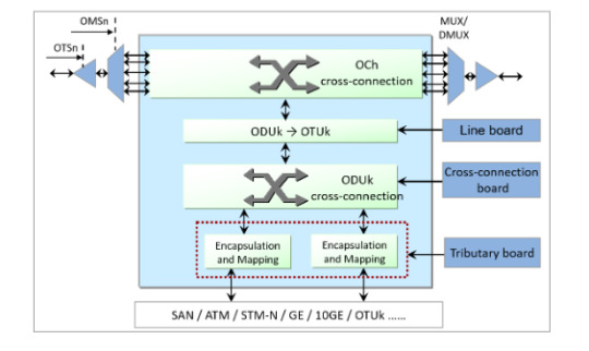
OTN: Optical Transmission Network Based on WDM, OTN integrates some advantages of SDH, such as abundant OAM overheads, flexible service grooming, and perfect protection modes. OTN service grooming is classified into optical-layer grooming and electrical-layer grooming. Optical-layer grooming can be considered as WDM. And electrical-layer grooming can be understood as SDH.
OTN site model:
Differences between WDM and OTN
1. The WDM technology applies only to the optical layer and does not apply to the electrical layer. OTN includes both the optical layer and the electrical layer.
2. On a traditional WDM network, one wavelength can transmit only one service. One wavelength on an OTN network can transmit multiple services at the same time.
3. Traditional WDM sites have only OTU boards (wavelength conversion units). In OTN, the OTU board is divided into two parts: tributary board and line board, and electrical cross-connect boards are added. OTU boards can also be directly installed on OTN products.
4. The powerful overhead and monitoring capabilities supported by OTN improve network self-healing protection and reliability. The WDM technology can provide only optical-layer protection. The OTN technology can provide both optical-layer protection and electrical-layer protection.
5. OTN supports more types of services and higher board integration.
6. Through electrical-layer cross-connection grooming, OTN can flexibly schedule and allocate channel resources, improving bandwidth resource utilization.
7. The WDM technology has no corresponding frame structure, whereas the OTN technology has a complete frame structure.
8. OTN sites use a large number of electrical-layer boards. Therefore, network construction costs are high. A WDM site does not have a large number of electrical-layer boards. Therefore, the network construction cost is low.
9. The application scenarios are different. Traditional WDM is mainly applied to the access layer at the edge of the network as an OTM site. An OTN network can provide cross-connections for large-granularity services. The OTN network can be used at the aggregation layer and core layer as OADM sites.
Note: The FOADM, ROADM, and OXC belong to new WDM technologies. This post is all about traditional WDM technologies.
0 notes
Text
Difference between MPU, LPU and SFU
The board of the network equipment NE40E, ME60 can be divided into MPU, LPU, and SFU according to the function.
Network devices are logically divided into the following three planes: data plane, control plane, and management plane.
The data plane provides high-speed non-blocking data channels to implement service switching between service modules.
The control plane performs the following functions: protocol processing, service processing, route calculation, forwarding control, service scheduling, traffic statistics, and system security.
The management plane monitors the running status of the system, monitors the environment, processes logs, and alarms, loads the system, and upgrades the system.
What is the MPU?
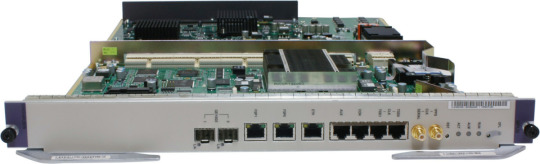
The full name of the MPU is Main Processing Unit, that is, the main control board. Responsible for the control plane and management plane of the system, including route calculation, device management and maintenance, and device monitoring. As a system synchronization unit, it provides high-precision and high-reliability synchronization clock and time signals. The main control board is like the management layer of the post office and is not responsible for the specific express processing (packet forwarding) work. The MPU interprets the device configuration and then transmits it to the LPU.
CR5D0MPUB570 main control board
What Is an LPU?
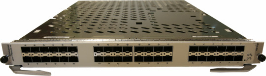
The full name of an LPU is Line Processing Unit, which is also called an interface board. The interface board with many interfaces is the interface board. Data packets are received and sent through the interface board. Communications cables must be connected to the interfaces of the interface board. The interface board provides different types of interfaces (such as optical and electrical interfaces) and different rates (such as 1000 Mbit/s, 10 Gbit/s, 25 Gbit/s, 40 Gbit/s, and 100 Gbit/s).
CR5D0EKGFA72 interface board
What Is SFU?
The full name of the SFU is Switch Fabric Unit, that is, the switch blade. To send packets from one interface to another interface, you need to connect the two interfaces. In practice, however, packets may come in from any interface and go out from any interface. If the point-to-point connection mode is used, too many connection cables are required. To solve the problem of a large number of connections, a switch blade is created. An interface board can communicate with each other by connecting to the switch blade with only one cable. The switch blade is one of the core components that determine the device performance. The switch blade functions as the sorting center of the post office. The interface blade collects data, sends the data to the switch blade for sorting, and then sends the data to the interface blade. Its efficient and timely offloading capability plays a key role in device performance.
CR5DSFUIT27R switching board

In addition, the device has other boards, such as Filler Panel, SRU, and SPU.
Filler panels are used to fill vacant slots for boards or sub-cards and provide electromagnetic shielding to ensure that the chassis meets electromagnetic radiation requirements. Fill vacant slots to ensure proper airflow for the chassis cooling system. Prevent dust or foreign objects from entering the chassis. Prevent internal circuits from being exposed.
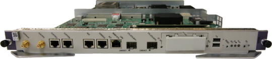
The SRU is a routing and switching board. It is composed of the MPU and SFU. Provides the control plane, management plane, and service switching plane of the entire system.
CR5D0SRUA770 Routing and Switching Board
The SPU is a service processing unit. Provides load balancing, firewall, NAT, IPSec, and NetStream services for devices.
0 notes
Text
How to Apply U2000 license for the OSN8800
Problem Description
As we know, to manage the optical equipment on the U2000 you need apply the NE quantity license for U2000.
But to manage OSN8800, only the NE quantity license is not enough.
Problem Analysis
For U2000V1R1 to V1R5 There are 3 types of license control items for OSN8800
1. OSN8800 NE quantity license.
2. OTN or SDH shelf quantity license.
3. OTN cross-connection capacity license.
The OTN shelf quantity license and OTN cross-connection capacity license are required only when the OSN8800 will include an electrical shelf.
And for OTN cross-connection capacity, there is 4 different Level License:
a. 360G cross-connection capacity
b. 360G-720G cross-connection capacity
c. 720G-1.28T cross-connection capacity
d. 1.28T-2.56T cross-connection capacity
Root Cause
Client enquiry
Solution Description
Example 1, the customer tries to add an OSN8800T32(NA) node in U2000, which has 8 electrical shelves with 1.28T cross-connection capacity. the expanded U2000 license should include.
1. 1 * LNSDNELC64 ----------------1 OSN8800T32(NA) NE license.
2. 8 * LNSDOTNFUN01 ------------8 OTN shelf quantity license.
3. 8 * LNSDPXCO8801 -------------8 360G cross-connection capacity license.
4. 8 * LNSDPXCO8802 -------------8 360G-720G cross-connection capacity license.
5. 8 * LNSDPXCO8803 -------------8 720G-1.28T cross-connection capacity license.
(U2000 has a bug, if you only have 1,2,5, it will also work, it will be fixed V1R7. so we still highly suggest applying for all 5 licenses).
Example 2, the customer tries to add 2 OSN8800T32(NA) optical shelves and 5 electrical shelves with 1.28T cross-connection capacity to an existing node. the expanded U2000 license should include.
1. 5 * LNSDOTNFUN01 ------------5 OTN shelf quantity license(only for the electrical shelves)
2. 5 * LNSDPXCO8801 -------------5 360G cross-connection capacity license. (only for the electrical shelves)
3. 5 * LNSDPXCO8802 -------------5 360G-720G cross-connection capacity license. (only for the electrical shelves)
4. 5 * LNSDPXCO8803 -------------5 720G-1.28T cross-connection capacity license. (only for the electrical shelves)
no license is needed to expand optical shelves.
(U2000 has a bug, if you only have 1,5, it will also work, it will be fixed in V1R7. so we still highly suggest applying all 4 licenses).
0 notes
Text
The OSN9800 M12 report the HARD_BAD alarm and COMMUN_FAIL alarms on the AUX board
Problem Description
The OSN9800 M12 report the HARD_BAD alarm and COMMUN_FAIL alarms on the AUX board

Problem Analysis
Device type:
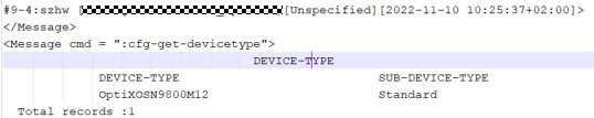
1. Checking current NE package loading status , which already finish the package loading:

2. Analysis the COMMUN_FAIL alarm , the parameter is 0x1,0x0,0x4, which indicate the communication with slot 1-74 F3AUX failed.

3. And check the HARD_BAD alarm, the parameter indicate that the Lan-Switch Link of the F3AUX boards in slots 1-74 is abnormal, which is an intra-board fault.

Root Cause
According to the preceding analysis, the HARD_BAD and COMMUN_FAIL alarms were reported because the F3AUX board in slots 1-74 was faulty.
Solution Description
1. apply the spare board TMF3AUX01*1 pcs(BOM: 03033VNA) and prepare a new cable;

2. Backup the database and then apply the operation windows;
3. Go to the site and then check if the cable between 0-74 CTU and 1-74 AUX is normal or not, if the cable is normal, please replace the board in slot 1-74 and wait for the board synchronize and then check if the alarm clear or not.
Note: After plug out the board, please make sure there is no bent pin or foreign object in the backplane, or the new board will be damaged.
0 notes
Text
How to delete logical fibers of OTN
This time, I will share with you how to use the correct method to delete logical fibers from OTN devices OSN1800V.
When we modify logical fibers of OTN devices, it should be delete existing logical fibers before creating new logical fibers. However, deleting logical fibers in the signal flow view fails.
Therefore, you can only use other methods to delete logical fibers.
The procedure is as follows:
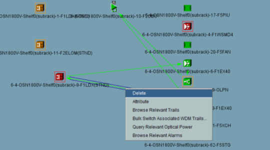
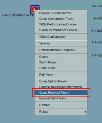
1. In the signal flow view, right-click aboard and choose Query Relevant Fibers from the shortcut menu.
2. In the fiber list, right-click the logical fiber to be deleted and choose Delete Fiber from the shortcut menu.

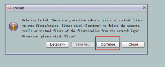
3. In the following screenshot, click Continue.
If we want to delete all logical fibers of a site, right-click an NE in the Main Topology and choose Query Relevant Fiber from the shortcut menu.

Select all fibers from the fiber list, and then delete the fiber using the preceding method.

Similarly, for an MSTP NE, if we want to delete the fiber (the fiber is configured with services or protection), we can also delete the fiber from the fiber list to ensure that the services on the fiber are not affected.
If the deletion cannot be performed on the NMS, run the following command:
:cfg-get-fibermgr:srcneid,srcbid,dstneid,dstbid (Query the current fiber configuration).
:cfg-del-fibermgr:SrcNeid,SrcBid,SrcPort,DstNeid,DstBid,DstPort
Parameter description: Source NE ID, Source slot ID, Source Optical Port No, Sink NE ID, Sink slot ID, Sink optical port ID.
For example:
:cfg-del-fibermgr:0x90001,1,2,0x90001,2,1
0 notes
Text
Packet lost on client port of 55TTX board
Packet lost on client port of TN55TTX board.
There are packets drops on end switch which connect with WDM device.
Problem Analysis
1. Checking the RMON performance and find current port usage is34.95%, which is reached the bandwidth of this port (3 timeslot ODUflex)

2. After checking the cross-connection and find there is no rest timeslot on the line board slot 8 59NS4.

Root Cause
The traffic received reached bandwidth (1.25*3G) and so that the package will be lost.
Solution Description
1. Suggest customer adjust the bandwidth on IP device side.
2. Suggest customer create another 10GE LAN service with adequate bandwidth and then migrate the service.
0 notes
Text
The H903MPLB Board Cannot Load the File After MA5800 Is Downgraded
After the MA5800 is downgraded from V100R021C00SPC105T to V100R019C12SPH202, the H903MPLB board cannot load the packet file V100R019C12SPH202_wholepackage(SPC200)_MPLX.bin.
The V100R019C12SPH202 software package does not contain the H903MPLB board.

According to the product documentation, the H903MPLB board is supported only in V100R020C10 and later versions.

The device version after the downgrade does not support the H903MPLB software.
The H903MPLB board cannot be downgraded from V100R021C00SPC105T to V100R019C12SPH202. You need to consider the mapping between boards and software.
0 notes
Text
Alarms in Huawei OSN 1800
This post about 2 alarms :
1- High Power in
2- High Power out
These Alarms can be appears in WDM cards, and the most popular ones are for transponder, such as LDX in Huawei OSN 1800.
The LDX board transponder connects to the client side with ports named Tx Rx and the WDM area connects to the port called in out.
Of course, if you find any alarms, then it will be on a certain port and a specific card in a specific shilf
Shelf, port, board..
You can learn the details by making collect WDM performance
And they can help you with all the details as :
1- Current board temperature
2- Current input power
3- Current output Power
4- Bias current for the board
5- Bit error rate after FEC
6- Errors before FEC
If the power is higher or lower than the allowed limit, it does what it is called:
Optical Power optimization .
You must know the WDM area limit. It means, for example, the permissible limit for reception is
-8, -9, -7, -10 dbm.
In these ranges almost, but if it is -1 dbm, for example, it is still not set.
I'll tell you a quick solution. If the switch on the port is high power, the quick solution remains is to add an attenuator, which has two types:
1- Fixed .
2- Variable (mechanical, electrical) .
The fixed attenuators have different types:
2, 5, 7, 10, 15 DB
This can be likened to the static resistance against optical power.
If you have a power, for example -2, and what is allowed is -8, the guest attenuator of its type is 5 DB
Preferably, you can also see the optical amplifier, EDFA or Raman, and the power out there as well as inside
0 notes
Text
General Power Module Fault Location Procedure on CE12800
General Power Module Fault Location Procedure on Huawei CE12800, power module troubleshooting flowchart:
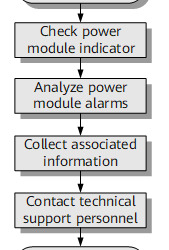
Procedure
1, Check the indicator on the power module.
For details about indicator states and meaning of each state, see the CloudEngine 12800 Hardware Description. You can determine the type of the fault based on the indicator state.
2, Check alarms on the power module and rectify the fault accordingly.
Run the display device alarm hardware command to check whether any alarms have been generated for the power module. If so, rectify the fault.
3, Collect the following information and contact technical support personnel:
Output of the display diagnostic-information command
Output of the display device power command
Output of the display device power system command
Output of the display device alarm hardware command
Output of the display alarm history command
Output of the display device elabel command
Indicator state on the power module
Log files and diagnostic log files
0 notes
Text
Users Are Unaware of Portal Authentication in Layer 3 Networking Scenario.
Huawei S12712 version: V200R010C00
On a Layer 3 network, traffic is diverted to the Huawei S12700, which functions as the Portal authentication point and is associated with the controller that functions as the RADIUS server. In Layer 3 networking, users' MAC addresses are not displayed on the S12700 after users are authenticated, so authentication unawareness cannot be implemented. (Authentication unawareness means that re-authentication is not required after the connection is disconnected for a period of time.) Run the authentication timer handshake-period command to change the handshake interval between the device and pre-connection and authorized users. The default interval is 300s.
Handling Process
Connect the terminal to the network and initiate the portal authentication. Then disconnect the terminal from the network. Run the display access user command on the S12700 within 5 minutes after the disconnection. The command output shows that the terminal is still online. The terminal is also in online state on the controller. Connect the terminal back to the network within 5 minutes, and no authentication is required. However, authentication is required if the connection is conducted more than 5 minutes after the disconnection. This test shows that the possible cause is that the authentication server does not send detection packets to the user. Run the authentication timer handshake-period command to modify the handshake period (300s by default) between the device and pre-connection and authorized users. Then, perform the test again. The test result shows that the user does not need to be re-authenticated within the handshake period, implementing authentication unawareness and therefore meeting customers' requirements.
Root Cause
By default, the handshake with pre-connection and authorized users is enabled. The default handshake period is 300 seconds. If the user does not respond within the period, the S12700 deletes the user entry. As a result, the user needs to be re-authenticated.
Solution
In the authentication profile view, run the authentication timer handshake-period command to modify the handshake period (300s by default) between the device and pre-connection and authorized users. Then, perform the test again. The test result shows that the user does not need to be re-authenticated within the handshake period, implementing authentication unawareness and therefore meeting customers' requirements.
0 notes