drdnar
10 posts
I misplaced a pointer and now I have to patch a leak.
Don't wanna be here? Send us removal request.
Statistics
We looked inside some of the posts by drdnar and here's what we found interesting.
Average Info
Notes Per Post
54K
Likes Per Post
31K
Reblog Per Post
24K
Reply Per Post
42
Time Between Posts
1 day
Number of Posts By Type
Text
10
Last Seen Tumblr Blogs


Fun Fact
69% of Tumblr users are millennials.
Text
TI’s TL431 datasheet is amazing. Their engineers clearly love the over-40-years-old part. The examples section makes it sound like it can do nearly anything short of make you coffee.
0 notes
Text
A Color LCD (displaying garbage)

I’m not sure what I expected a data test pattern to look like, but it wasn’t this. But I have confirmed something I feared: the display is actually portrait orientation.
0 notes
Text
the upside of ADHD is that it makes you a fucking genius
the downside is that you don't get to decide when and for how long you're a genius.
54K notes
·
View notes
Text
Well it's time to hook up the LCD to signals and see if it can actually display anything. It's entirely possible that it got fried by ESD while sitting in a box for years. It's equally possible that I just have no idea what I'm doing!
Case in point: I assumed VCOM meant another ground potential, but after just now looking more closely at the datasheet, it actually appears to be some kind of analog (contrast?) adjustment.
0 notes
Text
A Color LCD (part 2)
Today I finished and built the LCD case. The case is made of 0.5 mm cardstock and 2.2 mm cardboard, both upcycled product packaging. To make it, I drew up template artwork in Adobe Illustrator CS5.5 (I’m using that perpetual license until I die and Adobe’s SaaS can die in a fire), printed it, taped it over cardstock and cardboard, and then used a knife to cut up the cardstock and cardboard according to the template. Illustrator is definitely not a CAD package, but fortunately, I still remember how to do basic trigonometry and 2D vector math, with a little help from a TI-84 Plus CE. (I may be somewhat nerdy.)
Pictures below.

Picture of completed LCD case with test circuitry partially connected. The LCD’s backlight is powered, but not the rest of the LCD’s circuitry, so it just shows a white rectangle.
The inner shell and spacers are made from the 0.5 mm cardstock. The LCD is sandwiched between the front and back shell pieces, with a cutout for the image area of the LCD in the front, and a cutout for some circuitry on the flat-flex in the back. The black bars are cutouts for the spacers, which hold the LCD in place. The back shell has an additional slit for the flat-flex connector to go through. The tabs on the spacers go through the slits, and then get folded and taped down.


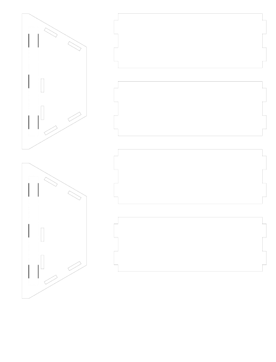
Artwork is rasterized at 150 DPI with transparency enabled, so if you can’t see anything, it’s because you’re seeing black lines on a dark background. The thick bars are cutouts and should be exactly 0.5 × 10 mm. Yes, that’s Dots Per Inch with metric measurements. Such is engineering in the US.
The outer shell, also made of 0.5 mm cardstock, folds around the inner shell, again with cutouts for the LCD image and the flat-flex connector. It is also taped in place. I tried to leave enough extra padding in the template so that, when folded, it wouldn’t be too snug, but it turned out to be a bit too snug anyway. The outer shell has tabs that insert into the trapezoidal side panels.
The side panels are made of 2.2 mm cardboard. The additional stiffness supports the LCD because I’m not sure the cardstock would be stiff enough. A rectangular back piece, also of cardboard, acts a strut to keep the back side of the trapezoid aligned.
For the shell and spacers, I only taped template paper to one side because the cardstock is thin. However, because the cardboard is much thicker, I printed mirror images of the trapezoidal side panels (and back panel), and taped them to both sides of the cardboard. This is especially useful for the small slits, which need to be cut out with fairly good alignment.
Finally, to interface with the LCD, I have a 50-pin ZIF connector breakout. It is mounted to another copy of the back panel, but positioned next to the LCD. The purpose of mounting the breakout (and indeed, of having a case at all) is to prevent strain on the LCD’s flat-flex connector.

Picture of the back of the LCD case.
0 notes
Text
A Color LCD (part 1)
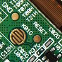
Many years ago, I pulled an LCD out of a GPS unit from the days before cars and smartphones having navigation features. This LCD is a color LCD with a backlight. It’s a very different technology, and much more challenging to interface to. I can’t even find a proper datasheet for the module.
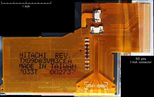
There are datasheets available for modules with similar part numbers. Based on the circuitry in the above picture, this looks like the closest pinout:
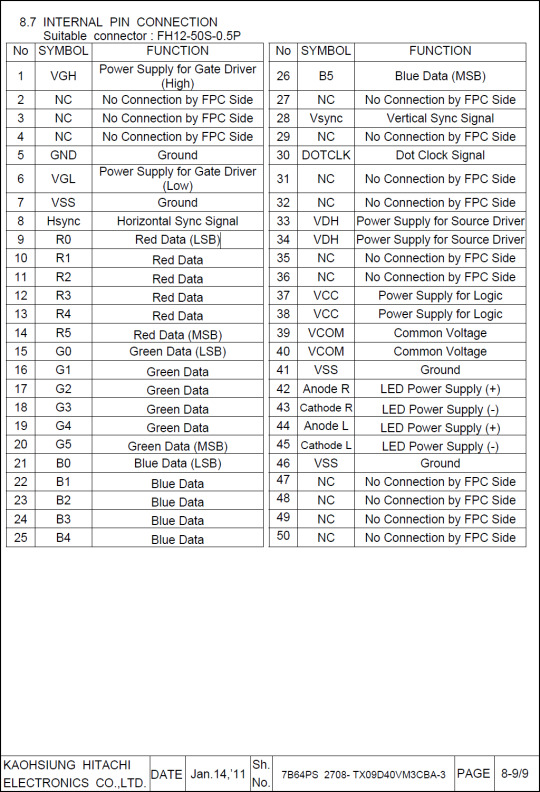
B&W LCD modules usually have a built-in charge pump to generate their needed voltages. Unfortunately, the datasheet also says this module needs those voltages supplied externally, and they’re a bit weird.
VDH: +8.3–+8.7 V @ 3.3 mA
VGH: +16.2–+17.0 V @ 0.23 mA
VGL: −8.35–−8.0 V @ 0.17 mA
VCC: +2.5–+3.3 V @ 0.22 mA (this is actually a normal voltage)
Fortunately, I don’t have to design and build a boost circuit myself; you can Just Buy voltage boost modules easily from many places. Getting a module to generate that negative voltage, however, is a lot harder. But it turns out that charge pump chips are A Thing you can Just Buy on Digikey. Sadly, charge pump chips tend to have fairly low output current capability, so while charge pumps could produce the high voltage for the backlight, it would require several and be kind of awkward.

So last week and this week, I finally sat down and learned enough about PIO on the Pi Pico to produce suitable timing signals for the module.

Great! I have a power circuit, I have logic signals, I have a suitable connector, now to see if I can display a picture. Well, one problem: I haven’t built something to hold the LCD. I don’t have a 3D printer, nor any CAD skills, so tonight’s project is to design in Adobe Illustrator a case for the module made of cardstock.
3 notes
·
View notes
Text
B&W LCDs
One of my recent hobbies has been pulling LCDs out of old devices and trying to get them to work. So far, I’ve gotten two B&W LCDs from old cell phones working.
I happen to like black and white LCDs. They’re a good compromise between being sunlight-readable, low-power, and updating fast. They consume mere milliwatts but unlike e-ink displays, can still display smooth graphics.
Most panels have a chip-on-glass (COG) integrated circuit of some kind. As the name suggests, it’s a silicon microchip epoxied directly on the same glass substrate as the LCD matrix. The chip acts as the interface between digital logic and the physical pixels on the LCD. The pixels themselves are analog things that require special driving signals with odd voltages and need to be refreshed several times a second or else the image fades; the driver chip takes care of all that. Depending on the application, the COG may have on-chip graphics memory (GRAM), so a microcontroller need not continuously resend image data.
Most B&W LCDs use an older pixel technology call super-twisted nematic that results in somewhat blurry motion. Essentially, it takes a non-zero amount of time for a pixel to change state, and for STN, that time is typically tens of milliseconds. The upshot of this, however, is that if you rapidly change a pixel between black and white, it never has time to finish switching to fully-dark or fully-light. Instead, it just oscillates at an in-between gray level. Based on some code by Wenting Zhang, I’ve managed to get grayscale working on my B&W LCDs.
The first LCD I got working was this 96×65 LCD from a Nokia 6340I. It’s the highest-resolution B&W panel I have. It appears to have a refresh rate of around 80 Hz, which is good for grayscale. Unfortunately, it also does not appear to have dual-ported GRAM, meaning that if you try to write to a pixel at the same time the driver is reading it during its refresh cycle, the read will be corrupted. This shows up on this display as a streak of black pixels.

The line moves over time because it depends on the precise microsecond-level timing between when LCD COG updates the pixels and when the microcontroller sends new pixels. Sometimes it goes off-screen entirely, and when the line isn't visible, the grayscale does look good. Unfortunately, there is no Vsync signal available to help synchronize writes to when the line would be off-screen.

On the other hand, this 96×32 module from a flip-phone does appear to have dual-ported GRAM. Not only that, but the driver appears to be a 96×64 matrix driver, meaning it has twice as much GRAM as it actually needs. Most drivers have a “scrolling” feature that lets you change which line of GRAM appears at the top of the screen. This means that whether or not it’s dual ported, you can send pixel data to the non-visible GRAM, and then instantaneously switch to the new frame.

The grayscale code tries to reduce how distracting the flicker is by applying a noise pattern, so that, instead of all pixels of a given gray level flipping at the same time, they flip at different times. This changes the flicker into more of a shimmer effect. Unfortunately, this LCD has both more responsive pixels and a slower refresh rate of about 40 Hz (which I can’t change), and I don’t think any algorithm can overcome those limitations.

0 notes
Text

If you know, you know.
0 notes
Text
Do I need to add an external capacitor for this LCD module?
Yeah I guess it needs a capacitor.
0 notes
Text
When you own an oscilloscope, you can just hook it up to things to see what's happening inside.
I got a little 150 W inverter (nominal 110 VAC out) for powering my laptop in a car. I can say that it meets or exceeds minimum standards for quality and safety. As advertised, the high-voltage output is fully-isolated. Also as-advertised, if you squint at the oscilloscope trace, you can see the modified sine wave output. This is different than a 400 W inverter I had that produces ≈150 V pulses on alternating pins and is not isolated.

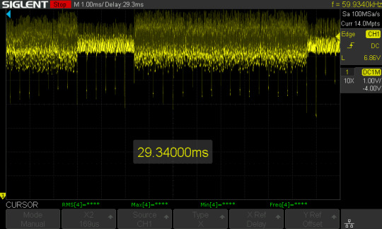
A few months ago, I got a USB-C PD charger that looks a little suspiciously cheap to me. The USB-C output actually worked OK: no noise, acceptable but unimpressive regulation. But the type-A port was garbage:

This is supposed to be 5 VDC, and it should handle > 2 A, but this is only a 1.6 A load. It should show 4.75≤RMS[1]≤5.25 so 4.68 V is out-of-spec and 880 mV peak-to-peak is way too much noise (the line should not have those spiky bits).
1 note
·
View note