
A log of things network related that I have come across, fixed and broken! The journal also serves as a good reference for my studies, CCNA and CCNP. If other network students/engineers can find something useful then this is also good! :)
Don't wanna be here? Send us removal request.
Statistics
We looked inside some of the posts by johntear-blog and here's what we found interesting.
Average Info
Notes Per Post
228
Likes Per Post
208
Reblog Per Post
20
Reply Per Post
0
Time Between Posts
27 days
Number of Posts By Type
Text
9
Last Seen Tumblr Blogs


Fun Fact
In 2020, 44% of users from Denmark used Tumblr daily.
Text
CCNA-Security Exam; Passed
I passed my CCNA-Security exam on Friday. 977/1000 - BOOM!
For anybody looking to take it, I got heavily tested on IPSec VPN, IOS Intrusion Prevention System and Zonal Based Firewalls, along with the basic encryption stuff, ACLs etc.
I got a switch simulation where I had to configure port-security, how spooky is that? My post here: http://johntear.tumblr.com/post/25374619695/switch-port-security explains how to do it.
And here is the fancy new logo:

Next move is on to CCNP. Starting with the SWITCH exam.
0 notes
Text
Switch Port Security
I recently had to protect the switch ports on a Cisco switch. This is a good idea for all businesses, particularly if the switches are not physically secured (in a comms room) or the switch ports are patched through to outlets in offices.
As far as I can see there are four methods for securing the ports on a Cisco switch:
Shut down the ports that aren't in use.
Use the Cisco proprietary method.
Use 802.1x to secure the ports.
A combination of 2 and 3!
802.1x Port Security
Number 1 is fairly simple and good practice if you aren't using 802.1x. 802.1x allows you to configure the switch ports so that when a device is connected it is authenticated against a AAA server (i.e. RADIUS) which in turn will send back an ACCESS-ACCEPT or ACCESS-REJECT packet based upon a number of attribute in the ACCESS-REQUEST packet (i.e. MAC Address or username and password).
Unfortunately this option wasn't open to me as the RADIUS server deployed on the site is only compliant with the original RADIUS RFC. The original RFC states that the authentication methods PAP and CHAP must be supported. For 802.1x security the RADIUS server must support EAP. So this was out of the question.
Cisco Method
This left me with using a combination of number 1 and number 2. The network I configure has a combination of switch ports with either 1 device (printer/server/access-point etc.), 2 devices (PC and IP phone) or no devices.
On the ports where I had no devices I simply issued the shutdown command on the interface:
switch(config-if)#shutdown
For ports where there was one device I configured port security with stick MAC addresses with shutdown on violation. This means that the switch learns which devices are connected to the switch port, learns the addresses and then shuts down the port if a rogue device is detected on the port:
switch(config-if)#shutdown
switch(config-if)#switchport port-security
switch(config-if)#switchport port-security mac-address sticky
switch(config-if)#switchport port-security violation shutdown
switch(config-if)#switchport port-security maximum 1
switch(config-if)#no shutdown
It is also a good idea to configure your switch to send log alerts to an SNMP server or a Syslog server so you know when there has been a violation on a switch port.
One thing I realised after configuring a switch port is that sometimes an IP phone was unable to connect. I read the Cisco documentation and they recommend using the following command when the switch port is in trunk mode:
switch(config-if)#switchport nonegotiate
3 notes
·
View notes
Text
EIGRP Metric Calculation
I set up a simple lab to have a look at EIGRP metric calculation:

The default metric calculation is as follows:
( 10,000,000 / lowest bandwidth ) x 256 + ( sum of delay ) x 256 = metric
An important note is that the delay is summed as tens of microseconds and the delay is shown in the router as microseconds. So if the interface shows 20000 usec then the calculation will use a value of 2000.
To calculate the metric for 192.168.1.0/24 we look at the router outputs for the interfaces on R2 we get:
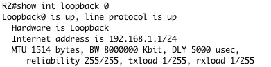

The lowest bandwidth is 128kbit on Serial0/0 and the sum of delay is 2500 so our calculation is:
( 10,000,000 / 128 ) x 256 + ( 2500 ) x 256 =
( 78125 ) x 256 + ( 2500 ) x 256 =
20,000,000 + 640,000 = 20,640,000
If we look at the routing table on R1 we can see that the metric for route 192.168.1.0/24 is as we have calculated it:

0 notes
Text
Frame Relay, EIGRP and Routing Tables
I was working through a lab for my CCNP ROUTE studies and came across a strange event when testing connectivity over a frame relay network by issuing ping commands between some network addresses.
My frame relay was set up fine and EIGRP was working fine. I tried to test connectivity between router WEST and one of the loopback addresses on router EAST but I got a timeout.
The way my topology was set up was that the HQ router had a PVC to router EAST and router WEST, but router EAST and WEST had no PVCs between them. So all routing between the EAST and WEST sites had to traverse the HQ router:

It took me a few minutes to realise what was going on but the diagram above shows what was happening. As the ICMP packets hit the EAST router it could not find an entry in the routing table for the source address other than the connected route 172.16.124.0 /29. If this was Ethernet then it wouldn't be a problem but because we are using Frame Relay and there is not virtual circuit back to the originating IP address I have to assume that the router is unable to return the packet because 172.16.124.3 has no frame relay mapping.
Here is the routing table of the EAST router:

Luckily Cisco allows some extra options in the ping command, one of which is to specify the source address of the ICMP request:
WEST#ping ip 10.2.1.1 source 10.3.1.1
By doing this the EAST router was able to route back by using the address 10.3.0.0/22 in the routing table and I could prove that I had end to end connectivity through my frame relay network.
If I wanted to map a route back to the WEST router serial interface I could simply add a frame relay map to the EAST router s0/0 interface:
EAST(config-if)#frame-relay map ip 172.16.124.3 201
Note here that we are basically saying that to get to 172.16.124.3 we send traffic via the local DLCI 201, which passes it to the HQ router for forwarding. You would also have to configure a map on the WEST router s0/0 interface for the return packets:
WEST(config-if)#frame-relay map ip 172.16.124.2 301
This doesn't look like a big deal in a simple lab, BUT it can cause issues on NBMA networks where pseudo-broadcasts are not allowed, that will be shown in a future post!
25 notes
·
View notes
Text
Updating Cisco Router IOS Remotely
Upgrading the IOS on a Cisco Router should always be done on site if possible. If you are unable to physically get to the site it is possible to update the router remotely.
You need to be running a TFTP server to download and upload from. You will also need to place the new IOS in the root folder for the TFTP server. In this example I am replacing c850-advsecurityk9-mz.124-15.T12.bin with c850-advsecurityk9-mz.124-15.T17.bin. I am also depicting the TFTP server at IP address 10.0.0.1.
First thing is to make a backup of the current IOS running on the router:
router#copy flash:c850-advsecurityk9-mz.124-15.T12.bin tftp://10.0.0.1
The next step is only required if you do not have enough space in the router flash to store both the old config and the new config:
router#delete flash:c850-advsecurityk9-mz.124-15.T12.bin
Now we can upload the new IOS from the TFTP server:
router#copy tftp://10.0.0.1/c850-advsecurityk9-mz.124-15.T17.bin flash
To ensure the IOS file is not corrupt it is best that you verify that the MD5 hash of the file matches what it is published as on Cisco's website:
router#verify /md5 flash:c850-advsecurityk9-mz.124-15.T17.bin cd0684b5b439fd3a6efcb8ec6fec81d4
If all is well you can issue the command that ensures the router uses the new image:
router(config)#boot system flash:c850-advsecurityk9-mz.124-15.T17.bin
That's it done! Reboot the router and the new image should be loaded up:
router#reload
7 notes
·
View notes
Text
Load Balancing Using Spanning Tree
Problem
I had a number of VLANs either side of a fibre optic trunk (8-core) between two buildings connected via two Cisco catalyst switches. The switches had 4 of the fibres connected in two pairs for redundancy. If one of the fibres failed the other would come online. Spanning tree is used to make sure both links don't come up at once and create a Layer 2 network loop.
By default spanning tree would drop one port for all VLANs (making the link unavailable) and bring one up for all traffic. This is not an efficient use of resources. What I required was to load balance over the two links, sending VoIP traffic down one link and data down the other.
Details
Main Switch: Cisco 4500 Supervisor.
Other Switch: Cisco 3560.
The default spanning tree setup would do this. Note that the main switch is the root bridge by default:

Note that data will traverse the links on Gi1/1 for all traffic (both VLANs).
Solution
The solution was to manipulate the way in which spanning tree selects the root bridge and how it selects which ports to block on a per VLAN basis.
First we manipulate the other switch so that it becomes the root bridge on VLAN 2:
OtherSwitch(config)#spanning-tree vlan 2 priority 0
We can also ensure that the main switch stays the root bridge on VLAN 1:
MainSwitch(config)#spanning-tree vlan 1 priority 0
Finally we manipulate the respective ports so they do not block (by setting their priority to 0):
MainSwitch(config)#int gig1/1
MainSwitch(config-if)#spanning-tree vlan 1 port-priority 0
OtherSwitch(config)#int gig1/1
OtherSwitch(config-if)#spanning-tree vlan 1 port-priority 0
OtherSwitch(config)#int gig1/2
OtherSwitch(config-if)#spanning-tree vlan 2 port-priority 0
MainSwitch(config)#int gig1/2
MainSwitch(config-if)#spanning-tree vlan 2 port-priority 0
You can confirm the status of the ports by issuing the show spanning-tree command in global configuration mode on each of the switches.
When VLAN 1 traffic is sent over the trunk the following topology will apply:
But, when VLAN 2 traffic is sent over the trunk the following topology will apply:

Note the different port that is blocked, and also note that a different fibre optic is being used to send the data. Now we can use two links to send data simultaneously without worrying about creating any loops in the network.
The important point here is that we still maintain a redundant network, if either of the links fail the other will be used to send traffic from both VLANs.
If we simply put the Gi1/1 ports on VLAN 1 and Gi1/2 ports on VLAN 2 we would not failover in the event of a cable/port failure because we would no longer be using spanning tree.
24 notes
·
View notes
Text
Configuring Network Address Translation
There are three main types of NAT that can be configured on a Cisco router. Here's what they are and how to configure them.
Terms
Inside Local - The IP address of a host on the inside network (usually a private IP address).
Inside Global - The IP address of the host on the inside network as seen from the outside network (usually a public IP address).
Outside Local - The IP address of the host on the outside network (usually a public IP address).
Outside Global - The IP address of the host on the outside network as seen from the inside network (rarely used).
The Network
The example configurations will use the following topology:

Static NAT
When we configure static NAT we want to translate our private IP addresses to a set of public IP addresses on a 1-to-1 basis. This means we need to have the same number of public IP addresses as the number of private IP addresses that we wish to translate. In this example we will configure the inside local address of 192.168.1.1 to the inside global address of 194.72.164.226.
First we configure the interfaces (which is inside and outside according to our NAT needs). Fa0/0 is the inside (192.168.1.254) and Fa0/1 is the outside (194.72.164.225):
router#conf t
router(config)#int fa0/0
router(config-if)#ip nat inside
router(config-if)#int fa0/1
router(config-if)#ip nat outside
Then we configure the static mappings:
router(config)#ip nat inside source static 192.168.1.1 194.72.164.226
Dynamic NAT
Dynamic NAT is similar to static NAT but it allows a pool of outside IP addresses to be used dynamically. This is good because you don't have to statically map an inside IP address to an outside IP address but it is bad because you can only use the number of outside IP addresses that you have been allocated. Once the outside IP addresses are in use any additional incoming packets will not be translated.
Configuring dynamic NAT is slightly more complicated. Like static NAT we configure the interfaces first:
router#conf t
router(config)#int fa0/0
router(config-if)#ip nat inside
router(config-if)#int fa0/1
router(config-if)#ip nat outside
Then we configure the pool of outside IP addresses we want to use (we have 14 in our example). This is fairly straightforward, we give the pool a name and assign the IP addresses to the pool, as well as the network mask:
router(config)#ip nat pool myPool 194.72.164.225 192.72.164.239 netmask 255.255.255.240
Then we configure the access list to define which addresses we want to translate:
router(config)#ip access-list 1 permit 192.168.1.0 0.0.0.255
Finally configure NAT, specifying our source list and the pool we want to use dynamically:
router(config)#ip nat inside source list 1 pool myPool
Port Address Translation (NAT Overload)
Port address translation (PAT) is probably the most common type of NAT used. PAT is how most 'home grade' routers handle the translation of private IP addresses to the public IP addresses used on the internet. PAT translates many inside local IP addresses to a single inside global IP address (194.72.164.225) by altering the source port of the outbound TCP/UDP segments.
The router keeps a reference to the translations it has made and changes them back to what they were before translation on return from the internet.
Again we configure the interfaces:
router#conf t
router(config)#int fa0/0
router(config-if)#ip nat inside
router(config-if)#int fa0/1
router(config-if)#ip nat outside
Then we configure the access list to define which addresses we want to translate:
router(config)#ip access-list 1 permit 192.168.1.0 0.0.0.255
Finally configure NAT, specifying our source list and the interface on which to overload (PAT):
router(config)#ip nat inside source list 1 interface fa0/1 overload
To see the translations in the table simply issue the following command:
router#show ip nat translations
83 notes
·
View notes
Text
Cisco Router Console Authentication Against RADIUS
Problem
A Policy requirement to authenticate users that connect to the console and VTY (telnet/SSH) lines using two factor authentication via a RADIUS server was made. I was required to configure a number of Cisco devices to comply with the policy.
Details
RADIUS Server: Proprietary Server Software running on Windows 2008.
Router: Cisco 2651XM 12.3(1a)

Solution
First I needed to enable AAA access control in global config mode:
router(config)#aaa new-model
Secondly I configured a RADIUS group on the router to where it will send it's authentication/accounting requests:
router(config)#radius-server host 10.0.0.1 auth-port 1812 acct-port 1813 key 7 asharedsecret
router(config)#aaa authentication login router-login group radius local
Note, here I have to tell the router the host address of the RADIUS server, the UDP ports it will send to and the shared secret used between the router and the RADIUS server to obfuscate the RADIUS packet contents.
The second line tells the router that we are defining a group, called router-login, that will use the radius server group for local login requests.
Finally, I had to configure the lines to use the router-login group:
router(config)#line console 0
router(config-line)#login authentication router-login
router(config)#line vty 0 4
router(config-line)#login authentication router-login
There is a couple of other things of note here. RADIUS supports both PAP and CHAP to obfuscate/hash the username and password in the packet. There is no command on the lines (console/vty) to configure the router to initiate RADIUS using CHAP. The default seems to be PAP.
The second thing to notice is that you can add more than one RADIUS server to the radius group, just simply add another line with the other server. If the first request times out then the router will send a request to the next server. This is very useful when thinking about having a backup RADIUS server.
You can also configure the timeout period before the router tries another server:
router(config)#radius-server timeout 3
Where the 3 is the number of seconds the router waits for a RADIUS response packet.
45 notes
·
View notes
Text
BAD ADDRESS entries in DHCP database.
Problem
Following the installation of a Cisco ASA our DHCP server on the same broadcast domain started listing BAD ADDRESS entries in the database when clients were trying to renew or get a new IP address. The result was that no client could could get a valid IP address and was reporting IP address conflicts.
Details

DHCP Server: Windows 2008 Server.
DHCP Client(s): Windows 7.
Firewall: ASA 8.4(2).
Cause
The DHCP process is as follows:
The client issues a DHCP DISCOVERY broadcast.
The server responds with a DHCP OFFER broadcast for the client.
The client issues a DHCP REQUEST unicast to the client.
The server responds with a DHCP ACKNOWLEDGE unicast to the client.
Finally the client issues an ARP request to see if the IP address is not in conflict with another client.
The problem is that the ASA responds to the ARP request making the client believe there is a conflict when in fact there isn’t. This makes the client issue a DHCP DECLINE to the server which in turn marks the address as being already in use (BAD ADDRESS).
The problem is further worsened as the client starts over the DHCP process again, the server issues another IP address, the ASA responds to the ARP request and the next address is rendered un-usable in the database. This process continues until all of the IP addresses in the DHCP pool are marked as BAD. No client on the broadcast domain is able to receive a valid IP address.
Solution
The cause was discovered/confirmed by installing Wireshark on a client machine and monitoring the DHCP process. It was found that the ASA was responding to ARP requests for IP addresses for which it did not use.
The ASA was configured to proxy ARP requests on the inside interface.
To disable proxy ARP on the inside interface the following commands were issued:
ASA# sysopt noproxyarp inside
Once the cause was found it was fairly simple to rectify. Without Wireshark it may have took some time to find!
#arp#arp cache#asa#broadcast#cache#cisco#dhcp#microsoft#sysopt noproxyarp inside#windows#i#ip conflict#ip
41 notes
·
View notes