This blog is a record of my electronic drum production process.https://open-e-drums.com/
Don't wanna be here? Send us removal request.
Statistics
We looked inside some of the posts by open-e-drums and here's what we found interesting.
Average Info
Notes Per Post
52
Likes Per Post
47
Reblog Per Post
2
Reply Per Post
3
Time Between Posts
1 month
Number of Posts By Type
Text
16
Note
1
Last Seen Tumblr Blogs


Fun Fact
Mobile Tumblr US users spend an average of 4.04 minutes per session on the app.
Text
Using a LCD Shield
I received an email that said, "I want to use LCD Keypad Shield.
Apparently, there is a shield with an LCD and 5 tact switches on it, which is sold by DFRobot.
I didn't even know what the shield was because I always used the LCD as a standalone module. However, it has 5 buttons, which is the same as the MIDI converter I made before, so it will be much easier to build a circuit with this shield.
So I got the shield, made by DFRobot, and bought it at amazon. A copy of HiLetgo would be cheaper.
However, it seems that you can't use the library as is. Because these five tact switches are read by a single analog pin. In my library, each tact switch is connected to one digital pin, so I need to add a new method.
This is a schematic, borrowed from HiLetgo.
There is a circuit for the tact switch in the center. It is a voltage divider circuit, and each button pressed leads to a resistor with a different value, so you know which button you pressed. This is useful.
It's a pain to consume one analog pin, but it's not a problem, especially if you use a multiplexer.
First, let's check the behavior using the sample AnalogReadSerial.ino originally included in the arduinoIDE. You don't have to make a circuit in particular. Just connect it.
This is the serial monitor when the button is pressed.
RIGHT : 0
UP : 205
DOWN : 405
LEFT : 622
SELECT : 823
none : 1023
Now that we know the value when the button is pressed, let's create a test code.
gist94cd6241f0acc96c6ae19c7f8691fc8d
This code only displays the name of the button you press on the LCD.
It is quite convenient that five buttons can be used only by connecting to Arduino UNO without building a circuit.
However, there seems to be a considerable individual difference in the value when the button is pressed. So the above code may also need to adjust the range of the if statement.
I've updated my library to use this button as well. You can update it from the IDE's library manager, or you can download it from the link below.
As mentioned above, there are individual differences, so adjustments may need to be made.
In the source code, lines 4279 to 4301 of hellodrum.cpp, there is an if statement to set the value of the button, so you can set it by editing the value there.
By simply connecting a shield and a piezo, you can edit the setting values using EEPROM. I think it would be easy to make a module if I made a shield to sandwich one more piece in between and put a multiplexer or jack on it.
2 notes
·
View notes
Text
Making Drum Synthesizer with Teensy
I am playing with Teensy as before. This time, instead of playing the wav file, I created the sound internally and play it.
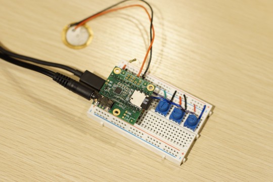
First, from the circuit. I used three variable resistors because I wanted a physical knob like a synth.
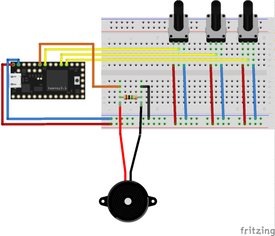
Wiring is very simple.
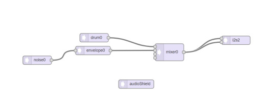
Next is the code. First, build an audio environment using the Audio System Design Tool from Teensy, which was introduced last time.
Unlike wav playback, it is simple. In the first place, a patch called drum is already prepared, so you can output sound just by connecting with i2s. This time I wanted to use noise, so put noise in envelope and connect drum and envelope from mixer to i2s.
I wrote the trigger code.
https://gist.github.com/2046d4af9e4f12aaba618d9c9036d89e
The envelope does not stop sounding unless you turn it off, so it is always in the noteOff state, and when the piezo responds, the drum and envelope are note on.
Here is the video.
youtube
I've always been sending MIDI, so it's fun to adjust the sound with the knobs.
The library was updated by adding the previous code and this code to the sample. Added knob class and organized folders.
Release Update Ver. 0.7.2 · RyoKosaka/HelloDrum-arduino-Library
0 notes
Text
Making WAV file player with Teensy
I made a prototype of wav file player with Teensy.
I used Teensy3.2 and audio shield. You need a long pin socket to use it with breadboard.
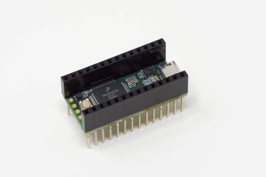
Attach ordinary header pins to the shield.
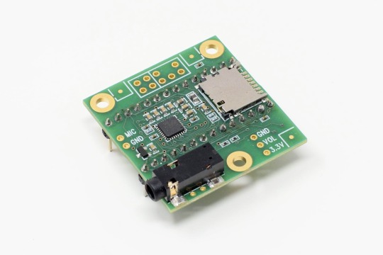
Use it like a photo. Please note that if you put the shield down, you can not use it with breadboard.
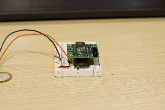
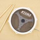
This time, only piezo is connected.
Details are written on the following page, but using this audio shield will reduce the number of pins that can be used with Teensy. https://www.pjrc.com/store/teensy3_audio.html
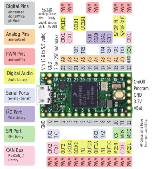
As you can see from the above figure, pins 14 to 23 are analog pins, but if you use a shield, 14, 15, 18, 19, 22, 23 cannot be used.
The available analog pins are 16,17,20,21. If many piezos are connected, a multiplexer is required.
Teensy can be developed using arduinoIDE by using software called Teensyduino. Installation is easy if you follow the official procedure.
※For Mac, Catalina still seems to be in beta.
Teensyduino - Add-on for Arduino IDE to use Teensy USB development board
First, watch this video because Audio features are too rich.
It’s long, but you can see most of the features.
As mentioned in the tutorial video above, Teensy provides a special tool called the Audio System Design Tool. Build an audio environment with visual programming.
This time, the audio environment was constructed as shown below.
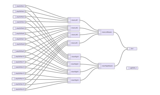
The “playSdWav” on the left is the Wav player. The reason why there are as many as 16 is that the number of sounds played simultaneously is the same as the number of playSdWav. For example, if you want to make the next sound while playing the previous sound when hitting repeatedly, if there is only one playSdWav, the previous sound will be stopped and the next sound will be played. That’s why it may be a bit more for the time being, but I’m preparing 16 for the time being. The mixer in the middle is a mixer as the name suggests. Each mixer has 4 channels, so you need 10 units to connect all as shown in the figure. “I2s” on the right is the audio output on the shield.
The sgtl5000 below is the chip on the shield. Although it is not connected to anything in the figure, it is necessary as a magic to use a shield.
You can build an audio environment like this by connecting patches. These can be exported as code.
I wrote a code that senses the piezo and changes the sound source according to the velocity. As always, I use my own library for piezo sensing.
https://gist.github.com/RyoKosaka/1399dd99065e2668f99befba74239ed2
playSdWav can determine whether it is playing with isPlaying (), so if there is a response to piezo, the sound source is played with playSdWav where inPlaying () is false.
Here is the video.
youtube
It corresponds to velocity. The reaction speed is very fast, but the choice of the sound source was not good or the dynamics could not be expressed much. Well, I only used only 5 wav files.
Regarding the sound source used, there is an open source VST plug-in called DrumGizmo, and I used a sound source called DRS Kit by DRS Drums released there. License is CC BY 4.0. Thank you.
Here are the wav files I used.
It works fine in the video, but sometimes it becomes unusable because it sometimes becomes unresponsive or crashes with the worst sound. It is easy to crash if you hit repeatedly. The cause is unknown at the moment … Is it possible to solve it with Teensy4.0?
Next time I will make a drum synthesizer with Teensy.
3 notes
·
View notes
Text
Project Web Site
I’ve always wanted to put data in one place, so I made a website.
https://open-e-drums.com/
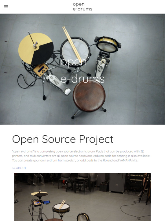
There is still a lot of information missing. I plan to release assembly manuals and parts lists and etc…
I wanted to make a 3D viewer. Using three.js, it was easy to implement.
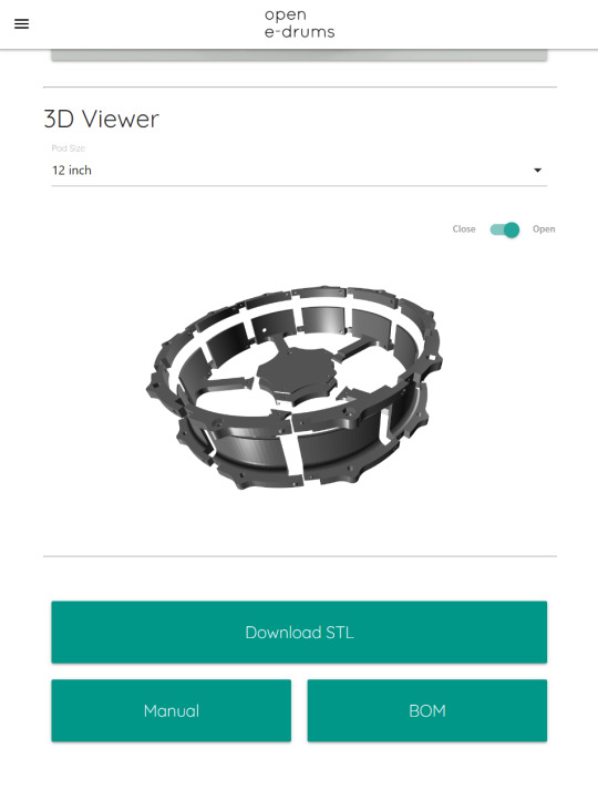
You can try it on this page.
Development hasn’t progressed for a while, but I’ll resume it soon.
2 notes
·
View notes
Text
Install from Arduino IDE
Good news. You can now install Hello Drum Library from the Library Manager in the Arduino IDE! Just search for "hellodrum".
2 notes
·
View notes
Text
Optical Hi-hat Controller for Roland
I designed the hardware to be used in a hi-hat stand.
It consists of four parts.
Let's start assembling.
Here are the necessary parts.
・TCRT5000 ・2.1mm DC Jack ・6.3mm mono Jack
Here is the circuit diagram. [NOTICE] I got a comment this circuit is not safe. It worked in my environment, but in the worst case it would destroy your module.
Make a circuit that fits in the case.
Put it in a case. The sensor and DC jack are secured with a glue gun.
Cover with a M3 -10 mm bolt. It's OK if the sensor is facing straight up and you can see it clearly.
Next, it is the part that covers the sensor. Insert M3 nut and M3 -10 mm bolt.
The back of this part covers the sensor, but it doesn't react well if it's black, so I put a masking tape on it. You don't need to do this if you print with white filament.
Let's install it on the stand.
The cable is secured with a cable tie. The trigger is on the left, and the power supply is on the right.
I used Yamaha PCY 135 for cymbals. You can use it as it is, but I made it a little bit. This part is to prevent cymbals from shaking when you close the high hat.
Attach it to the PCY 135. First, remove the 3 screws at the center of the back.
Insert the printed part and tighten the screw again. Don't over tighten.
That's it. Now, let's use it.
Install the cymbals. A picture viewed from the side.
A picture viewed from the side when closed.
Here is the video.
youtube
It's finished better than I thought and I can use it without any problem. It's a little noisy because I don't put anything like cushion material on it, but there should be no problem if you put something in it. The wiring of the circuit is a little troublesome, but it can be made quite easily.
You can download the 3D model here.
2 notes
·
View notes
Text
TCRT5000 with Roland TD-10
I used TCRT5000 with Roland sound module TD-10.
I've made some changes to the circuitry introduced in the previous article
This is the circuit. However, it is still under adjustment, so it may change.
I made it with a breadboard.
As you can see in the picture, a 5V power supply is required.
Let's try TD -10.
youtube
This is good.
The hi-hat of ATV needs a power supply, so I think it is almost the same design. So is ATV's Hi-Hat Controller compatible with Roland's modules?
I would like to try it on a hi-hat stand, but I need to plug in the power cable, so I need to redesign the hardware. Next time, I will do hardware design.
1 note
·
View note
Text
Disassemble Roland VH-10
A little while ago when Roland released the TD -17, a hi-hat called the VH -10 was released.
There are some differences in specs, the VH -11 uses a metal part for the controller, and the cymbal part is slightly thicker and heavier.
I use an older Roland sound module TD-10 with TDW-1, which supports VH-11. The basic structure of VH-10 and VH-11 are similar, so VH-10 worked just fine with my TD-10.
VH -10 doesn't have much information, but this video explains the difference between VH -11 and VH -10 in detail.
youtube
Let's take it apart.
The VH -10/VH -11 consists of a cymbal and a controller.
The cymbal part is on hold this time. It's just a piezo and a film switch. I will compare it with cymbals made by YAMAHA next time.
Disassemble the controller. You just need to remove 3 screws on the bottom.
It will look like this when the bottom lid comes off.
A flexible board is a sensor. Same as FSR, variable resistance. A white roller attached to the front part rolls over the sensor to detect its position. If the roller touches the sensor directly, the sensor may be damaged, so a silicone sheet is attached.
If you're building your own, you can use SoftPot.
The roller is rolling over the sensor to detect the position. It's hard to see in the picture, but it's structured so that the roller is pressed against the sensor with a spring. It's a simple structure.
I didn't think I needed to take it apart any more, so I put it back.
Next, let's look at the signal on the oscilloscope. The high-hat controller uses a stereo cable, so it has three wires.
Wire it as shown in the image below and read the voltage on the yellow line that connects to pin A0.
The results are as you would expect. Press to increase voltage.
And it goes down when you release it.
Let's watch it on GIF.
This controller uses FSR that I made before. As you can see from the oscilloscope signal, you can use it with the Roland sound module.
I made a hi-hat controller with TCRT 5000 before, but I didn't know much about it at that time, so I didn't think about the circuit carefully.
I think I can use this in the Roland module if I modify the circuit a little. What I like about the optical type is that it doesn't need mechanical structure, so it's easy to design. And less parts.
I don't know if I can, but next time I'll see if an optical high hat controller using TCRT 5000 will work with the Roland sound module.
3 notes
·
View notes
Text
Library Update Ver. 0.7
I updated Hello Drum library
https://github.com/RyoKosaka/HelloDrum-arduino-Library/releases/tag/0.7
・Improved sensing ・Dual Piezo sensing available (Test) ・ESP32 EEPROM available ・Setting mode with I2C LCD or I2C OLED available ・Add sample code ・Add example circuit
youtube
youtube
4 notes
·
View notes
Text
ESP32 BLE MIDI PAD - Part 1
Last time I tried using an analog multiplexer with ESP 32, I had 8 piezo connected to a small breadboard, so it was difficult to tap and adjust.
So, this time I made a prototype of octapad I also updated the library. Version 0.6 is available.
Release Update Ver. 0.6 · RyoKosaka/HelloDrum-arduino-Library · GitHub
Now, what I did this time was, 1. Hardware design of the MIDI pad 2. Library Update - ESP32 support 3. Library Update - Analog multiplexer(4051) support
1. Hardware design of the pad
Start with hardware design. It's just a prototype for code adjustment, so it's pretty rough, and it's not designed to fit the board neatly.
Since the piezo are close to each other, the plate that becomes the pad is independent. I wanted to think about the wiring while making it, so I made many loopholes on the side. Holes for screws are made everywhere in order to secure to the plate material on the bottom.
Now, let's put it together. It's better to make a plate with a laser cutter. It's just a board.
The frame is a bit big, so I divided it up and output it as usual. Secure with 3 mm bolt.
I made the bottom board with cardboard and fixed it with double-sided tape so I didn't use the hole.
Pass a wire for the piezo.
Insert the EVA foam so that the plate and frame do not touch directly. I cut it into small pieces with a cutter and stuck them together with hot melt glue.
Attach EVA foam to the plate.
Connect wires to the piezo
Paste the piezo on the back of the plate.
The hardware is now complete.
I thought so, but the EVA foam on the plate might absorb the shock too much and the hit doesn't reach the piezo well. Oh, no.
So, once the EVA foam on the plate was removed and the piezo is on top. I think it would have been faster to stick the piezo on one board...
Well, it's a prototype for now, so I'll adjust it with this.
2. Library Update - ESP32 Support
Since I made my own library, I would like to use it with ESP32. I couldn't compile it as is, so I will update the library to work with ESP32.
When I looked at the error message, I couldn't compile because I was using the EEPROM library. I'm using an arduino's genuine EEPROM library, but it seems like it only works with AVR, and ESP 32 seems to have another EEPROM library... For now, I want to use only the sensing part with ESP32.
So AVR boards use a genuine EEPROM library, not ESP32.
\#ifdef _AVR_ //code executed only in AVR \#endif
I have enclosed all EEPROM related parts such as include. Of course you can't use EEPROM with ESP32, but you can use hello drum library with ESP32.
3. Library Update - Analog multiplexer(4051) Support
Currently, the library is used like this. (Example of connecting only one piezo to the A0 pin of arduino)
\#include \#include MIDI_CREATE_DEFAULT_INSTANCE(); int PAD1[5] = { 800, //sensitivity 150, //threshold 5, //scan time 10, //mask time 38 //note }; HelloDrum pad1(0); //connect to A0 pin void setup() { MIDI.begin(); } void loop() { //read piezo value pad1.singlePiezo(PAD1[0], PAD1[1], PAD1[2], PAD1[3]); if (pad1.hit == true) { MIDI.sendNoteOn(PAD1[4], pad1.velocity, 10); //(note, velocity, channel) MIDI.sendNoteOff(PAD1[4], 0, 10); } }
I tried to use it in the same way as possible. (Example of Piezo Connected to Pin 0 of 74HC4051)
\#include \#include MIDI_CREATE_DEFAULT_INSTANCE(); int PAD1[5] = { 800, //sensitivity 150, //threshold 5, //scan time 10, //mask time 38 //note }; HelloDrumMUX mux(2,3,4,0);//D2, D3, D4, A0 : MUX Pin HelloDrum pad1(0); //pad1 connect to mux's pin 0 void setup() { MIDI.begin(); } void loop() { //scanning all pin of mux mux.scan(); //read piezo value pad1.singlePiezoMUX(PAD1[0], PAD1[1], PAD1[2], PAD1[3]); if (pad1.hit == true) { MIDI.sendNoteOn(PAD1[4], pad1.velocity, 10); //(note, velocity, channel) MIDI.sendNoteOff(PAD1[4], 0, 10); } }
I briefly introduce how to use it.
I've created a new class called HelloDrumMUX. Name the 4051 and declare the pin connection.
HelloDrumMUX mux(2,3,4,0);//D2, D3, D4, A0 : MUX Pin
The method scan in the loop scans the 4051, as the name implies.
mux.scan();//scanning all pin of mux
Also, there is no change in the class of the pad. However, the pin number of the 4051 to which the piezo is connected is described.
HelloDrum pad1(0); //pad1 connect to mux's pin 0
And pad sensing simply appends "MUX" to the end of existing methods.
pad1.singlePiezoMUX(PAD1[0], PAD1[1], PAD1[2], PAD1[3]);
That's all. You can use it almost as you used to. I've also added new sample code. Added "muxSensing.ino" and "muxSensing_ESP32.ino" samples.
A movie about "muxSensing_ESP32.ino" is here.
youtube
Hmm. I think I need to adjust more....
4 notes
·
View notes
Text
Using MUX (74HC4051)
I tried an analog multiplexer. I knew of an analog multiplexer, but I didn’t use it.
I used the familiar 74HC4051.
I connected 8 piezo’s to an ESP32 using a 74HC4051 and tried BLE MIDI communication with a PC.
Although the number of analog pins can be increased by using an analog multiplexer, it is not actually increased. By switching the switches in the IC at high speed, the number of analog pins can be treated as if it were increased. So it is also called an analog switch.
What’s different is the resistor and the diode. In the past, only one resistance of 1 MΩ was connected to one piezo. Like this.
However, I connected this same circuit to the 74HC4051, and when I hit 1 piezo it all reacted and it was useless. Recalling that MegaDrum used the 74HC4051, I tried the circuit and found it somewhat better.
MegaDrum is MIDI trigger module has been under development since 2007. The main IC is ATmega 324 p. You can download the schematics and firmware and create a parts list, but the firmware source code is not available. You can just make your own. But the schematics are helpful. According to a Vdrum forum thread, MegaDrum’s input analog circuitry is very similar to Roland’s TD-10.
Now, the code. There is nothing particularly difficult. The Sparkfun tutorial is easy to follow. If you just want to read the value, you can use the following code. It just switches with the for statement.
https://gist.github.com/RyoKosaka/cac5935d894f208e4c32fe6a13e8e573
Now you can read the eight piezo values.
I could read the value, so I could sense it using my old code and send a MIDI signal. But I want to use my own library for the sensing part.
So I made my library compatible with ESP32 and analog multiplexers. But I need to adjust the codes and circuits more.
Here’s a video of a test using the library.
youtube
3 notes
·
View notes
Text
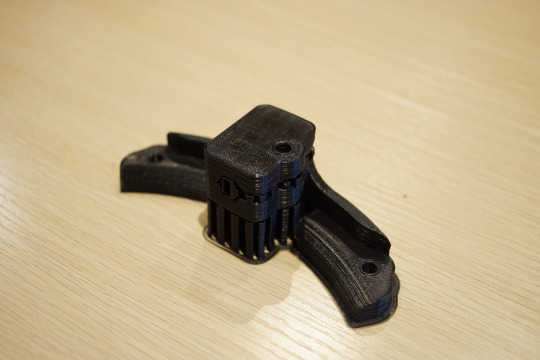
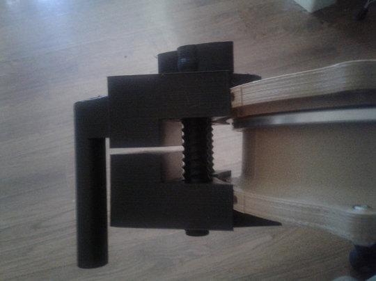
Use your tom holder
I designed a part that can be used with the tom holder.

These parts are one of the most important parts. I should have designed it earlier.
1. For Roland
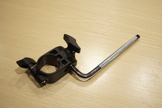
The rod is round and knurled for non-slip. Same as TAMA. The design is simple. It would be fine if there was simply a hole.
OK, Let’s print.
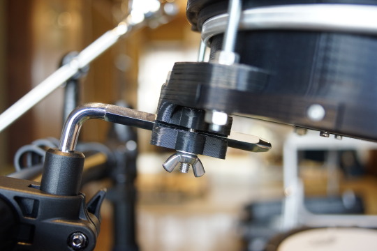
Use M6-30mm bolts and wing nuts.
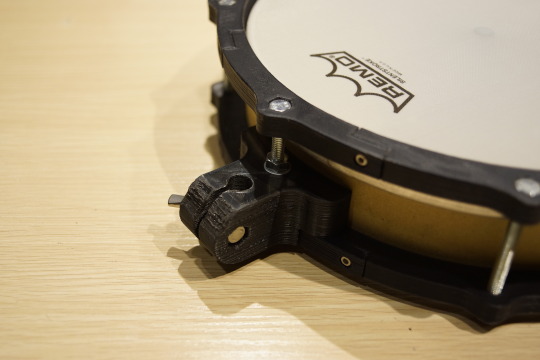
Attach it to the stand. It is firmly fixed. Thanks to the knurled rod, it does not slip at all.
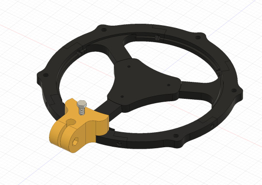
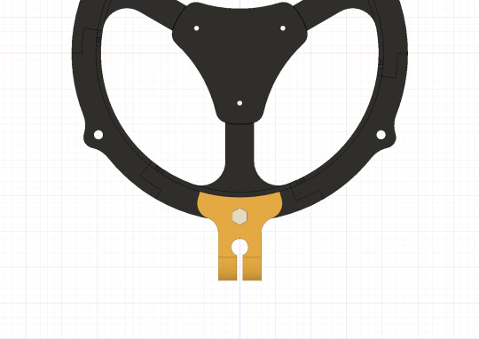
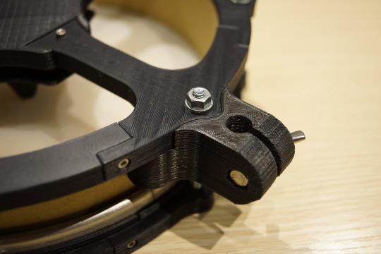
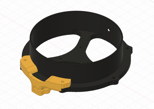
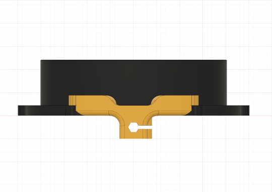
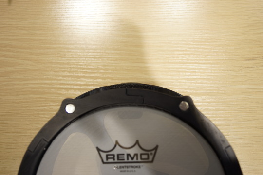
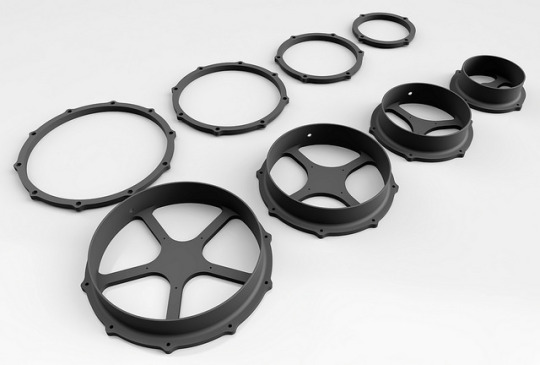
I also designed for the version with a shell.
Available from 6 inches to 12 inches. I tested for 8 inches and 10 inches. It will be usable for 6 inches. However, 12 inches is anxious about strength.
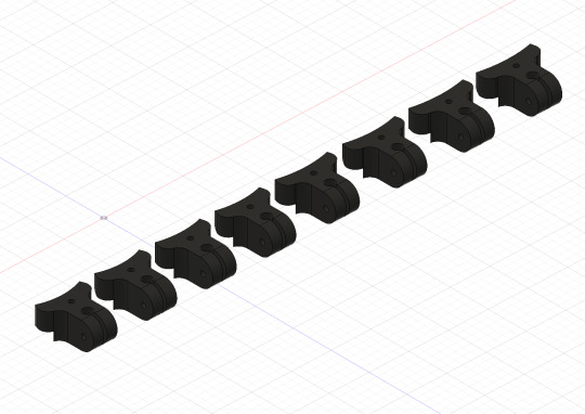
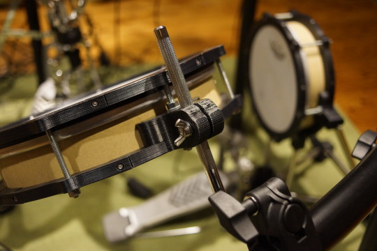
2. For YAMAHA
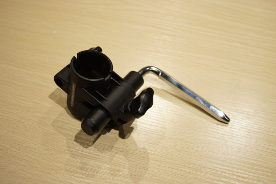
Yamaha's rods are hexagonal. And the surface is slippery.
And, as you all know, it's 90 degrees different from Roland's rod.
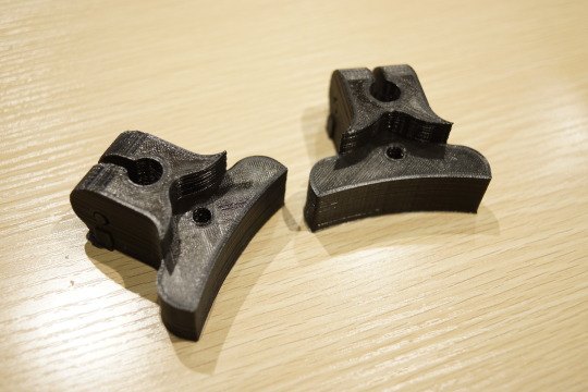
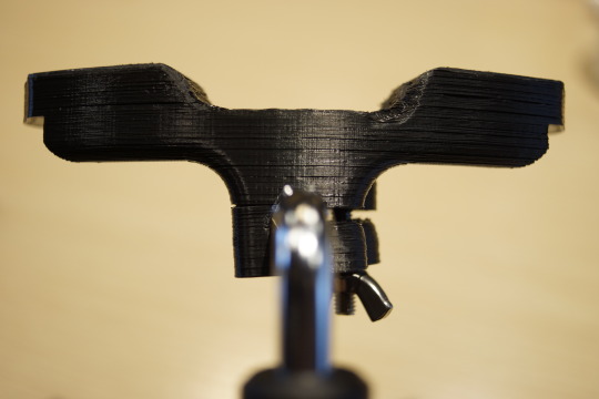
It is a little tricky design. I don't think this is the best. This is a prototype. Anyway, let's print.
Use M6-30mm bolts and wing nuts.
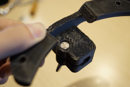
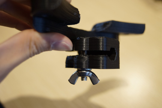
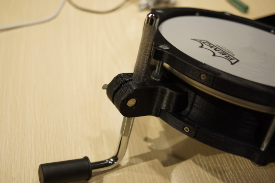
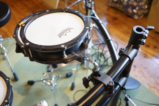
Attach to the pad. It looks large, but from the top it's less noticeable.
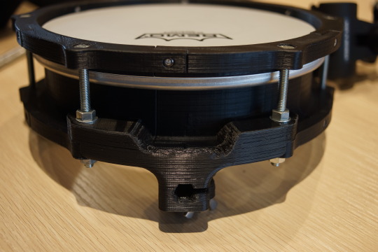
Attach to the drum stand. Since the surface of the rod is slippery, the pad will slide slightly even if the nut is tightened. However, it seems that the pad does not come off the rod during play.
It seems that I tightened too much, and the parts got cracked ...
The cause is that my printer's modeling accuracy is low, the setting was not optimal because it was the first filament used, and this part structure.
I published the current 3D model data, but It will be improved.
3D Model
You can download 3D models from Thingiverse.
For Roland : https://www.thingiverse.com/thing:3512038
For YAMAHA : https://www.thingiverse.com/thing:3513928
2 notes
·
View notes
Text
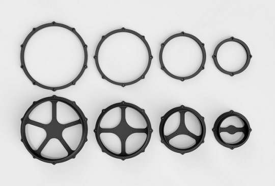
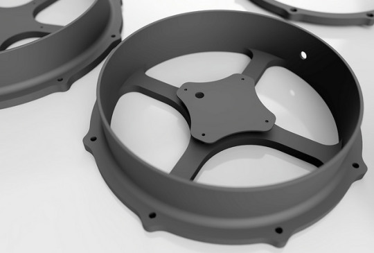
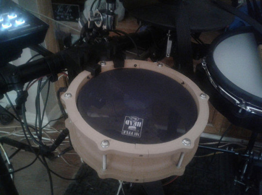
Printing One Piece Shell and Rim
There was model I designed but not printed.
And now, this model has been printed in France!
https://www.thingiverse.com/make:626939
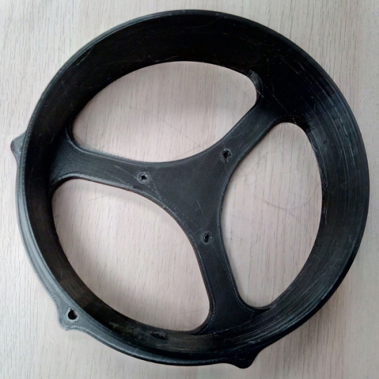
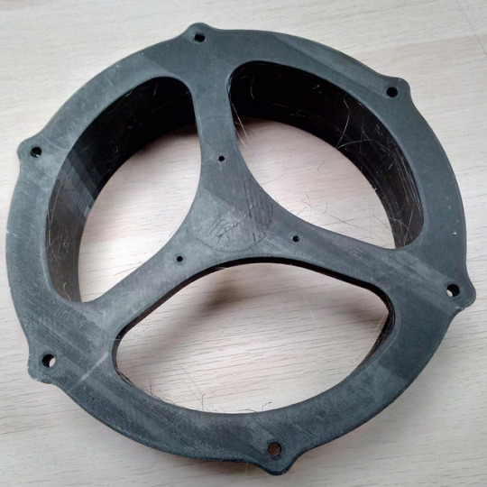
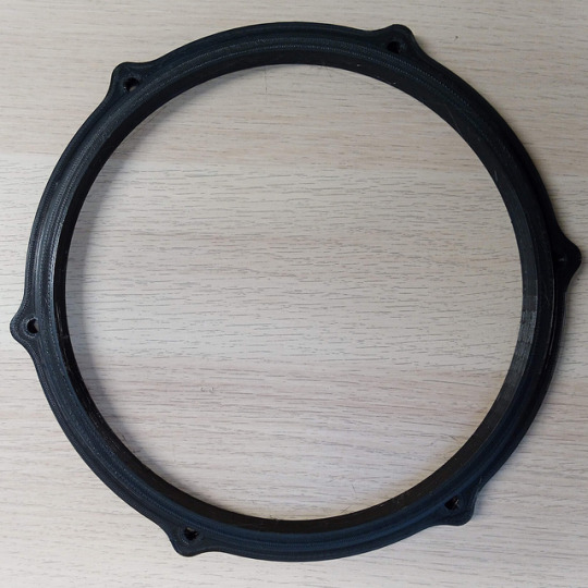
He also printed a 10-inch split pad. And he shared the video.
youtube
It is attached to a Yamaha drum rack. nice...
By the way, I ordered a Roland drum rack.
Both Yamaha and Roland have the same drum rack pipe diameter, 38.1 mm.
It's time to design mounting parts for drum racks. You're gonna love it.
Print and photo by Wapata
Thank you very much for sharing.
1 note
·
View note
Text
Using BLE MIDI
I tried connecting to the PC wirelessly using BLE MIDI.
The board to use is ESP32.
ESP32 is a convenient board that can be developed with ArduinoIDE, it is available with less than half the price of genuine arduino UNO even though WiFi module and Bluetooth module are built-in.
By using bluetooth low energy, you can connect the ESP32 to the PC or smartphone and make it recognize as a MIDI device, so that you can send signals wirelessly.
Let's do it.
First of all, initial setup is necessary to use ESP32. It is explained in detail on this site. please refer.
https://randomnerdtutorials.com/installing-the-esp32-board-in-arduino-ide-windows-instructions/
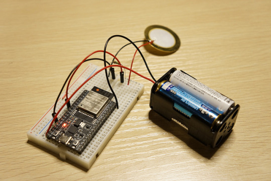
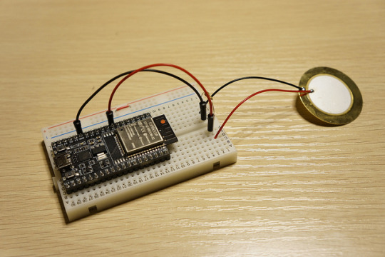
Refer to the figure below for the circuit. Since it can also feed from USB, the battery box is not necessarily required.
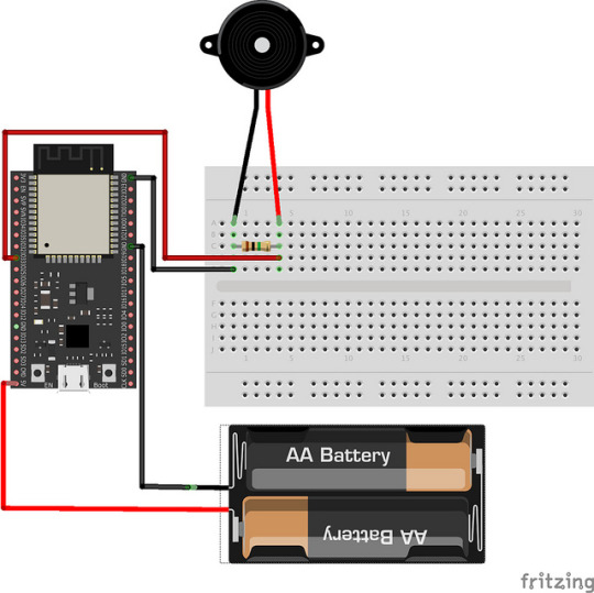
Remove the battery box when writing the code.
Next is the code. This thread is helpful.
https://github.com/nkolban/esp32-snippets/issues/510
I merged the code at the beginning of this thread with the piezo sensing code I made earlier.
https://gist.github.com/RyoKosaka/1f488427e02054422966fb9625c9f8e5
Unfortunately neither arudino midi library nor hellodrum library is currently available for BLE MIDI.
I plan to make the hellodrum library correspond to ESP32 either.
Finally, connect ESP32 and PC.
Is this your first time using BLE MIDI? Do not worry. KORG makes a very easy-to-understand manual in multiple languages.
https://www.korg.com/us/support/download/product/1/305/
youtube
How is it? I was surprised at the low latency. BLE MIDI is very useful.
Next time I will put this prototype in the 3D print pad.
4 notes
·
View notes
Note
hi, your project is awesome,, what type of arduino do you use? UNO or MEGA? thank you,,
I am using both UNO (R3) and MEGA (R3).My code works on both UNO and MEGA.
1 note
·
View note
Text
Do you have a large 3D printer?
One-piece shell and rim are available now.
https://www.thingiverse.com/thing:2945590
2 notes
·
View notes
Text
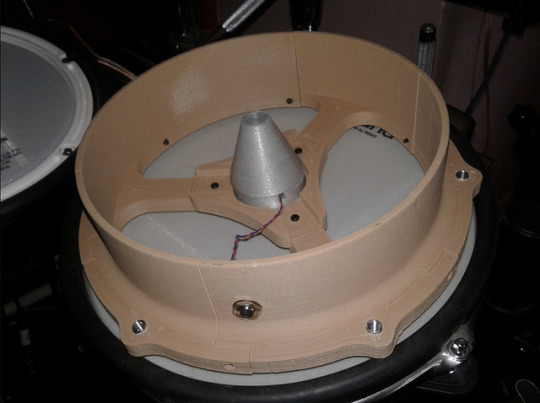
Making Trigger Cone with 3D Printer
One Maker made a pad and uploaded a picture to Thingiverse. From North Carolina.
https://www.thingiverse.com/make:493582

Interestingly, he seems to have made a trigger cone with a 3D printer.
Of course the material is not PLA but NinjaFlex is a highly elastic filament.
It's a brilliant solution. I have not tried the easiest way to make it with flexible filaments.
You can purchase ninjaFlex from the adafruit.
https://www.adafruit.com/product/1690
youtube
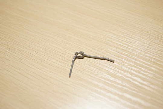
Unfortunately, in Japan, it was sold at a very expensive price, so I bought a TPU filament.
https://www.sainsmart.com/products/all-colors-tpu-flexible-filament-1-75mm-0-8kg-1-76lb
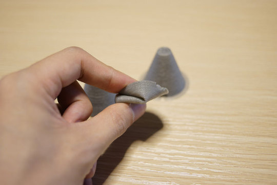
It is very soft. I can bind it.
I measured the dimensions of the trigger cone and modeled it and printed it with TPU.
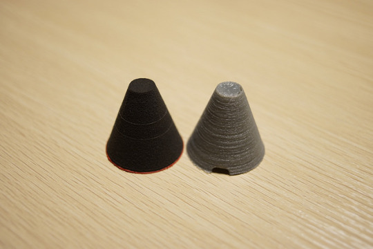
The setting of infill is 20%, 10%, 0%.
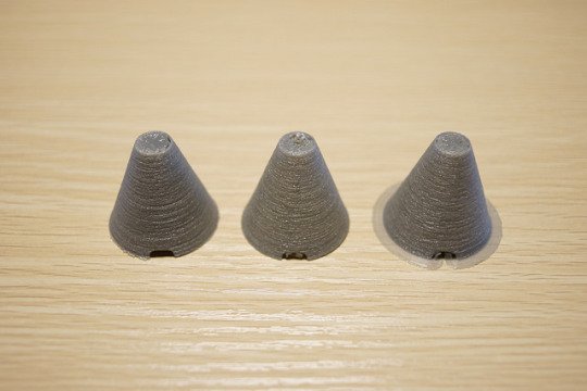
At 20%, the cone was too hard. At 0%, the cone was too soft.
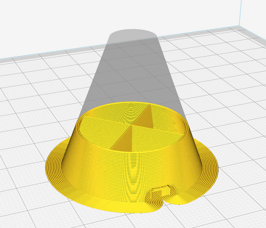
The center of cone is just good hardness, but the wall of cone is conical so it is strong against the force from the top.
Clearly the feel was different from sponge form, but when we tested it by connecting to Roland's TD-10 it was able to be used without problem.
Unfortunately, with the library I wrote, it could not sense the vibration of piezo better than sponge form. It seems that the power is too strong and the noise of the signal is too much.
By improving the shape of the cone, it may be possible to sense well. I will try it.
By the way he also uploaded the mount parts for roland.
https://www.thingiverse.com/thing:2924429
https://www.thingiverse.com/thing:2921879
16 notes
·
View notes