
Last Seen Blogs

cosplaytheory
Cosplayer,Theorist

tesoro64
Sin título

realityhelixcreates
Stories and Art

ederdeo
Eder Deó

Text
Fallen at the last fence
Unfortunately during last minute testing and bug fixing late Saturday evening, the motors became energise without turning on the cooling fan. The fatal result was the loss of one of the motor driver modules with no replacement spare part, so we were unable to compete with a faulty robot.
This is not the end though. Development of the machine will continue as autonomous robotics is one of our passions. I have started a new blog now to document the ongoing improvement of what will now be PiDER-4.2 or maybe just PiDER-42 as that number I'm told is the answer to the universe and everything.
https://www.tumblr.com/pider-42
0 notes
Text
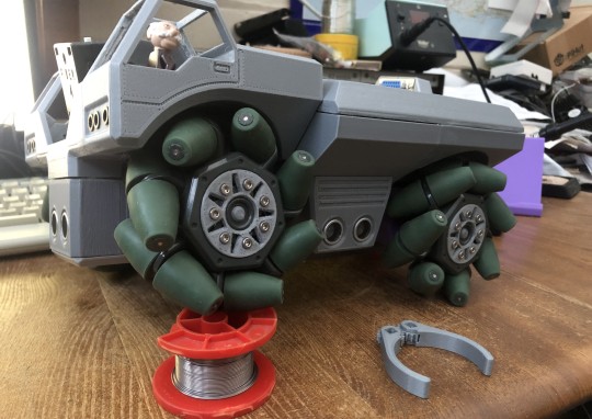
The most important consideration to be made when using Mecanum wheels is for them to work correctly all four should touch the surface at all times.
Our solution to this is to have a body that is able to twist somewhere along its length, enabling stable movement over very uneven ground.
1 note
·
View note
Text
I'm sure I don't need to tell any 'Good' software engineer that regression test is essential.
i.e. Test, test, test and then test some more. Every time you change or add code to your system, even if it is unrelated to other parts as a whole, the entire system should be tested to ensure there are no knock-on effects from the code that has changed or newly added.
Zombies are a particular problem, especially when you have a crazy Animal in control of the blaster, who prefers to shoot everything except Zombies.
0 notes
Text


Here is a sample of menu's that the PiDER-4 code can generate on the Remote controllers graphic display, and at all times there are two bar graphs that show the battery state of the robot and the remote.
0 notes
Text

A question of control.
The faithful remote that I (Pete) designed for PiDER-3 in 2019, is still by far the best system for the job.
Having spent a short while looking at remote handsets in 2018 and discovering that there was nothing that came 'Remotely' close to anything useful. Forgive the pun. I decided the answer was to make my own that delivered everything I required from a remote controller.
This is based around a PIC24 16-bit Microcontroller. It has six push switches, two analogue joysticks, a monochrome graphic display and Bluetooth connectivity. I decided to leave everything exposed, because why would you cover up a work of art.
0 notes
Text


The Nerf Blaster is now complete with the most viable Entity on the planet in control, ready and willing to blast some Zombies
0 notes
Text

We decided at an early stage that rather than reinventing a Nerf shooting mechanism, it is easier to use a standard motorised gun and replace the motor run switch with a TIP122 Darlington transistor and the firing trigger with a servo.
Top left shows the simple connection interface board for the motor run and the servo plugs. For reliability we always use ribbon cables with IDC connectors on virtually all interconnects between modules.
Bottom left shows the Robot's attachment 15-pin 'D' socket that carries +12V, +5V, 0V, Three PWM lines, Two binary attachment ID lines, One sense Input and One binary (on/off) Output. From these signals we have concluded that we can support three unique attachments, or the sense line could be included in the attachment ID providing a possible 7 unique attachment units. The remaining binary code (i.e. 0) signals NO attachment.
0 notes
Text

This is the home made Pi HAT for PiDER-4.
Our original plan was to use a standard RPi camera module at the end of the boom, hence the reason for the cut-out to allow access to the camera socket. We decided that image processing using a Pi camera is far too processor intensive so we finally decided to use a far superior Pixy2 camera for the job instead.
0 notes
Text
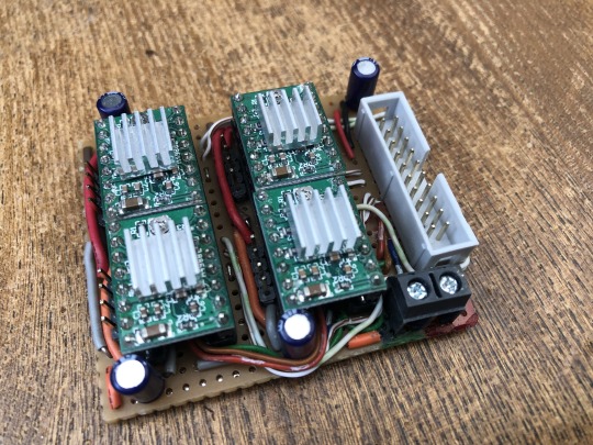
Stepper motors can of course be driven by standard H-Bridge's, but it is not the ideal solution. The best way is to use dedicated Stepper driver modules like those used with 3D printer control boards that provide Micro Stepping for smooth motion control.
This is my four stepper motor driver board. It measures 60mm x 55mm containing four A4988 Stepper driver modules to drive four short body Nema 17 motors. Current limiting on each is set to 700mA which provides powerful motor control without over heating each of the very compact motors.
0 notes
Text
8-Dec-2023
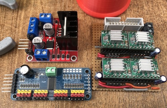
Now a little bit about extra electronic modules, that are readily available off the shelf. The modules shown in the picture and the reasons for using them is described below. There will be an update at some point showing a homemade hat to plug onto the top of the Pi, which is still having circuitry added to it and probably a Teensy Microcontroller to accurately measure the four distances from ultrasonic transducers plus the robot battery level. It might even do the PWM's aswel instead of the 16-Channel PWM board but we haven't decided on that yet.
4x Micro-Stepping motor driver modules mounted on a piece of FR2 Matrix Stripboard, for convenience of connecting to the RPi and the individual Short body Nema-17 Stepper motors. This way the motors can be controlled more accurately with direction and step pulse. These modules also provide current limiting and as stated, Micro-stepping which can provide smoother and better movement accuracy.
1x 16-channel PWM board to drive servos and probably LED’s to make the Robot a bit more flashy (Yet to be confirmed). The use of such a module is mainly because it is impossible to get a stable PWM from the Raspberry Pi. Most likely because the RPi PWM is a software generated pulse and not from a dedicated hardware counter, compounded by the Real time OS that is pulled in all manner of directions by higher priority level interrupts. It causes the PWM from the Pi OS to jitter like crazy, which in turn causes a servo to twitch rather a lot. So if you want accuracy and stability then a separate dedicated module is needed, as the RPi cannot provide either.
1x Dual H-Bridge. One of the channels is to drive the Boom’s 12V linear actuator. The second channel is spare in case we need it for some other hardware that we haven’t thought of yet.
0 notes
Text


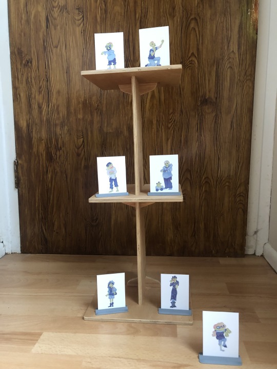
8-Dec-2023
This is our tower for testing the Zombie Apocalypse. It is just short of 600 mm tall but will be good enough for testing.
0 notes
Text

8-Dec-2023
Another part of the development is testing. Here you can see our 3D printed red and green barrels for testing the Eco Disaster coding, once we have finished developing the Grabber attachment to clip onto the front of PiDER-4 for that particular challenge.
0 notes
Text


8-Dec-2023
Having now coded most of the system using C++ for remote control. This being a major milestone in the build. We have started thinking about the five autonomous challenges for the Advanced category that we will be competing in.
In 2019, I (Pete) personally wrote all the computer vision code entirely on my own in Python. This time around I wanted to give OpenCV a try to see if it is as useful as people claim it to be. The problem is it does not build or install on the Raspberry Pi 3B that we intend to use in the robot. I have followed multiple instruction and tried multiple versions of the Pi OS and previous versions of OpenCV and every time there are numerous errors resulting in failure.
I have now wasted more than a week on this and have concluded that OpenCV is a complete waste of my time and I will just write my own computer vision code again, but this time in C++. At least I know my code will work which is more than I can say for OpenCV, which is a tremendous shame.
0 notes
Text


8-Dec-2023
Almost got the Boom arm figured out, allowing the system to have a bird’s eye view of the arena that wil be advantageous in many of the challenges. The boom will also carry the Nerf gun attachment for the Zombie Apocalypse challenge.
0 notes
Text


This is the new design for the wheel motor shaft adaptor. It has turned out much nicer looking than I had imagined. Just three more to print now.
0 notes
Text

Here are the first encounters with failure in the build process. The problem with FDM printing is the weakness between print layers. Time to rethink the hub adaptor design.
0 notes
Text

Things are coming together nicely now. In this image we are figuring out where the various modules are going to be. Still lots of body parts to design and print though :-)
0 notes