
Don't wanna be here? Send us removal request.
Statistics
We looked inside some of the posts by swiftaugustblog-blog and here's what we found interesting.
Average Info
Notes Per Post
0
Likes Per Post
0
Reblog Per Post
0
Reply Per Post
0
Time Between Posts
1 month
Number of Posts By Type
Text
17
Last Seen Tumblr Blogs


Fun Fact
Tumblr is available in 18 languages.
Text
How to Mount a Network Switch to a Rack?
A network switch has been recognized as one of the most important devices for today’s networking technology. It allows simultaneous transmission of multiple packets and partition a network more efficiently than bridges or routers. The rack mount switch can be installed in a standard 19-inch equipment rack or on a desktop or shelf. So how do you mount a network switch to a rack to establish network wiring connections? Here’s a step-by-step guide to teach you how to mount a network switch to a rack.
Preparations Before Mounting the Network Switch
Before rack mounting the switch, please pay attention to the following factors:
Location: The site should be at the center of all the devices you want to link and near a power outlet, so that it is accessible for installing, cabling and maintaining the devices in the rack.
Temperature: Since the temperature within a rack assembly may be higher than the ambient room temperature, check that the rack-environment temperature is within the specified operating temperature range (0 to 40 °C).
Mechanical Loading: Do not place any equipment on top of a rack-mounted unit.
Circuit Overloading: Be sure that the supply circuit to the rack assembly is not overloaded.
Grounding: The switch rack should be properly grounded.
How to Mount a Network Switch to a Rack?
Step1. Attaching the Brackets to the Switch
Attach the brackets to the network switch using the screws provided in the mounting accessory.
Step2. Installing the Switch in the Rack
Mount the switch in the rack with the optional rack mount kit, usually using the rack-mounting screws. Be sure to secure the lower rack-mounting screws first to prevent the brackets being bent by the weight of the switch.
Step3. Adding Other Switches into the Rack
If there is only one data switch to be installed in the rack, then you can make the connection to a power source now. If there are multiple switches to be mounted, you need to install the another switch on the top of the first one in the rack, and then attach the power cords.
Step4. Attaching the Power Cords
After you complete mounting all of the switches in the rack, it’s time to connect the switch rack to the power source. Remember to verify that you have the correct power supply (AC-input or DC-input and the correct wattage) for your configuration.
Caution: To prevent bodily injury when mounting or servicing the switches in a rack, you must take special precautions to ensure that the system remains stable. The following guidelines are provided to ensure your safety:
This network switch should be mounted at the bottom of the rack if it is the only unit in the rack.
When mounting the switch in a partially filled rack, load the rack from the bottom to the top with the heaviest component at the bottom of the rack.
If the rack is provided with stabilizing devices, install the stabilizers before mounting or servicing the switches in the rack.
Establishing Network Wiring Connections
After mounting your network switches to a rack, you can establish the network wiring connections according to your requirements now. If you’re using a Gigabit Ethernet switch, it can be connected to 10, 100 or 1000Mbps network interface cards in PCs and servers, as well as to other switches and hubs. It may also be connected to remote devices using optional SFP transceivers. No matter which type of network switches you are using, make sure that they are securely mounted in the rack and connected to the corresponding networking wiring systems.
Source: http://www.fiber-optic-tutorial.com/mount-network-switch-to-rack.html
0 notes
Text
Proper Horizontal Cable Management for Rack
Cable management is a critical part of network cabling systems that require a large number of moves, adds and changes. The improper cable management may result in cable damage or cause transmission errors and performance issues as well as system downtime. In a horizontal manager system, the cable management for rack is important in telecommunications rooms for leased office space, brokerages and trading houses where the workstations will move or add additional ports frequently. This post will analyze why the horizontal rack cable management is important and offers FS horizontal cable management solutions for rack.
Why Is Proper Horizontal Rack Cable Management Important?
Poorly routed cables can lead to an assortment of problems over time. Jumbled cables would increase the risk of cables to be tangled up, and a possibility of interruption when reconnecting the cables.
The rack cable management is directly related to hardware safety. All equipment running on the server rack is going to generate heat, so organizing a rack with a conception involving space will help promote the airflow and hardware management.
Cable labels in a proper horizontal rack cable management can save a lot of time on troubleshooting. Just imagine how difficult it would be to trace a cable through that mess.
If rack cables were unorganized, a technician would spend hours tracing wires when something goes wrong. In most circumstances, we can’t afford to stay offline while a technician unravels a tangled nest of cables. Thus a proper horizontal cable management makes it easy for the technician to identify and access where goes wrong and fix it in far less time.
Horizontal Cable Management for Rack: Where to Start with?
Horizontal cable management system is often installed within racks or cabinets to manage cables on front racks and draw cables away from equipment neatly. The rack space of a horizontal cable management infrastructure is typically 1U or 2U high. The following part gives the FS plastic & metal horizontal fiber patch panel, cable managers, lacer panels to promote a proper cable management in your horizontal network cabling systems.
Horizontal Rackmount Fiber Patch Panel
Horizontal rackmount fiber patch panels help to organize cables and eliminate cable stress for your rack enclosure cabinet. FS offers 1U 19’’ blank rackmount fiber patch panels with plastic D-rings on the cable management panel and lacing bar. These rackmount fiber patch panels can be used to organize cables for fiber optic adapters, fiber enclosures, Ethernet switches, WDM chassis, etc.
Horizontal Cable Managers with Finger Duct & Brush Strip
Horizontal cable managers with finger duct and brush strip allow neat and proper routing of the patch cables from equipment in racks and protect cables from damage. Fixed inset fingers on the front and back allow easier access to the ports for moves, adds, and changes. And the brush strip horizontal cable manager is constructed of high-quality steel with high-density nylon bristles, which can promote proper airflow through the rack and meet the demand for front-to-back cable runs.
Horizontal Lacer Panel with D-rings
Horizontal lacer panels are efficient tools for rack or enclosure cabling. These D-rings on the lacer panel are essential to avoid cable strain and prevent damage to the ports on your rack-mount equipment. The five rotating D-rings can be easily assembled or disassembled manually according to your needs.
Conclusion
This post provides users with a horizontal cable management solution that simplifies cable routing in a finished professional appearance. With proper and efficient horizontal cable management tools, cable spaghetti is not a problem anymore. You can just have a peace of mind and reap the great benefits of sound cable management. FS horizontal cable management tools provide an efficient way to manage high performance copper, fiber optic, or coaxial cables on any 1U or 2U rack. For more details, please kindly visit www.fs.com.
Originally published at http://www.fiber-optic-tutorial.com/proper-horizontal-cable-management-rack.html
0 notes
Text
Cloud Computing vs Big Data: What Is the Relationship?
Cloud computing and big data are two of the most trending terms in the ever-lasting IT sector nowadays. You may think that they both do the same thing but actually, both of them have their own ways to work to perform. Cloud computing vs big data, what are they? What is the relationship between them?

Cloud Computing Tutorial
Cloud computing is a technology used to store data and information on a remote server rather than on a physical hard drive. It uses the servers hosted on the Internet to store, manage, and process data, rather than a local server or a personal computer. It means accessing resources of organization from any remote location in the world. In simple term accessing RAM, HDD, Processor of organization’s server from laptop, desktop from any of the location where Internet is available.

As shown in the figure above, cloud computing is collection of different services, providing services to end user via the Internet. Services like storage, virtual desktop applications, Web/App hosting process power from servers. In the following architecture, the infrastructure built to provide services is called cloud computing. This infrastructure from where the services gets accessible is front end.
Big Data Wiki
The term big data is very popular nowadays, representing huge sets of data that can be further processed to extract information. Big data carries hidden patterns and algorithms which are unlocked by using various tools available in the market. These data sets are further analyzed to provide business insights. Big data is all about storing and processing of data that is exponentially growing these days. Giants like Google, Facebook are having their own data centers to keep track and to secure their users’ data. That’s also why many big companies are equipped with reliable network equipment (including the server, router or fiber switch) for data storage or traffic forwarding in their data centers. For high performance and cost-effective enterprise routers, Gigabit Ethernet switch and 10gbe switch, FS is a case in point.

Big data requires a large amount of storage space. While the price of storage continued to decline, the resources required to leverage big data can still pose financial difficulties for SMBs (small to medium sized businesses). A typical big data storage and analysis infrastructure will be based on clustered network-attached storage (NAS). Clustered NAS infrastructure requires configuration of several NAS pods with each NAS pod comprised of several storage devices connected to an NAS device. The series of NAS devices are then interconnected to allow massive sharing and searching of data.
Key Comparisons Over Cloud Computing vs Big Data
The cloud computing works in a consolidated manner, while the big data comes under the technology of cloud computing. The crucial difference between cloud computing vs big data is that cloud computing is used to handle the huge storage capacity to provide various flexible and techniques to tackle a magnificent amount of the data. While big data is the information processed with cloud computing platform. The following chart gives a more detailed comparison over cloud computing vs big data.
Cloud ComputingBig Data
BasicOn-demand services are provided by using integrated computer resources and systems.Extensive set of structured, unstructured, complex data forbidding the traditional processing technique to work on it.
PurposeEnable the data to be stored and processed on the remote server and accessed from any place.Organization of the large volume of data and information to the extract hidden valuable knowledge.
Working ModeDistributed computing is used to analyse the data and produce more useful data.Internet is used to provide the cloud-based services.
BenefitsLow maintenance expense, centralized platform, provision for backup and recovery.Cost effective parallelism, scalable, robust.
ChallengesAvailability, transformation, security, charging model.Data variety, data storage, data integration, data processing, and resource management.
Cloud Computing vs Big Data: They Work Hand in Hand
Both cloud computing and big data are good at their marks. Cloud computing vs big data: they differ from each other but work hand in hand. They are the perfect combination for data storage and processing. The cloud computing has been a precursor and facilitator to the emergence of big data. If big data is the content, then cloud computing is the infrastructure.
Originally published at http://www.fiber-optic-tutorial.com/cloud-computing-vs-big-data-relationship.html
0 notes
Text
VLAN Configuration Guidelines on Layer 3 Switch
As networks grow larger and larger, scalability becomes an issue. Every device in the network needs to send broadcasts to communicate in a broadcast domain . As more devices are added to the broadcast domain, more broadcasts start to saturate the network. In this case, VLAN (Virtual LAN) is needed to separate broadcast domains virtually, eliminating the need to create completely separate hardware LANs to overcome this large-broadcast-domain issue. In this post, we’re gonna expound the motivators to deploy VLAN and how to set up VLAN configuration step by step.

Motivators to Implement VLAN
VLAN is a way of creating multiple virtual switches inside one physical data switch. There are a lot of reasons to implement VLAN, some of which are listed as follows.
Link Utilization: Link utilization is another big reason to use VLANs. Spanning tree by function builds a single path through your layer 2 network to prevent loops. If you have multiple redundant links to your aggregating devices then some of these links will go unused. To get around this you can build multiple STP topology with different VLANs.
Service Separation: If you have IP security cameras, IP Phones, and Desktops all connecting into the same switch it might be easier to separate these services out into their own subnet. This would also allow you to apply QoS markings to these services based on VLAN instead of some higher layer service. You can also apply ACLs on the device performing Layer 3 routing to prevent communication between VLANs that might not be desired.
Subnet Size: If a single site becomes too large you can break that site down into different VLANs which will reduce the number of hosts that see need to process each broadcast.
VLAN Configuration Guidelines on Layer 3 Switch
Configuring two or more VLANs to communicate with each other requires the use of either a VLAN-aware router or a Layer 3 switch. VLAN configuration can be accomplished either in CLI interface or in Web interface. The following video is a VLAN configuration example on FS S5800/S5850 10 gigabit switch.
Configure VLAN in CLI (command-line interface)
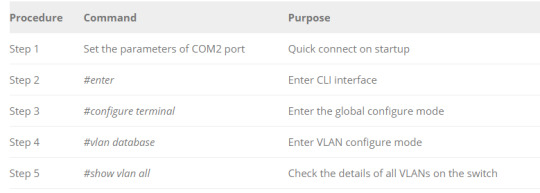
Here we take FS S5850-32S2Q Layer 3 switch as an example to configure VLAN. To create a VLAN via CLI interface, SecureCRT software is required to enter CLI interface, then perform the VLAN configuration command in the chart below:
Configure VLAN in Web Interface
Configuring VLAN in Web Interface is quite simple. Just perform the following two steps and you would see the basic info of the VLAN that is created.
Step 1: Log in the Web user interface using the account and password
Step 2: Find the service management and create a new VLAN, and set its ID as 10 or 20.
Note: Ports configured to use VLAN 10 act as if they’re connected to the exact same switch. Ports in VLAN 20 can not directly talk to ports in VLAN 10. They must be routed between the two or have a link that bridges the two VLANs
Summary
VLAN deployments make it easy for network engineers to partition a single switched network to match the functional and security requirements of their systems without having to run new cables or make major changes in their current network infrastructure. The proper VLAN configuration on Layer 3 switches ensures reliable and secure data link access to all hosts connected to switch ports. Knowing more about VLAN configuration would allow you to use them when you need them and to use them correctly when you do.
0 notes
Text
LAN vs WAN vs MAN: Which One to Choose?
Network is essential for establishing communications among devices such as computers, routers, or fiber switches to operate over the area they cover. LAN ((Local Area Network), WAN (Wide Area Network) and MAN (Metropolitan Area Network) are the three most prevalent types of networks that are utilized today. There are some similarities and differences between them. LAN vs WAN vs MAN, which one should you choose?

What Is LAN?
LAN is an interconnection of a group of related networking devices within a small geographical area where the distance between these devices is small. Some of the LANs also cover the networks in office , school, and home. Most of the LANs are built for the purpose of sharing vital resources such as printers and exchanging files.
LAN is also widely used to provide services such as sharing computer applications, gaming and accessing the internet. This type of network is under the control of one administrator who is in charge of the configurations and settings and other devices connected through Ethernet cables and wireless routers.
What Is WAN?
WAN is a kind of network connection between multiple networking devices over a large geographical area. The connection can be between different cities or even countries. A WAN network can be a collection of small networks that have been combined, or it can be as a result of various private business entities. One good example of WAN is the internet, since it connects computers from different corners of the world.
The WAN network is too complex to be managed by private administrators. Therefore, WANs usually have a public ownership, where network devices in this network can be connected either by cables or through a wireless connection.
What Is MAN?
As the name suggests, MAN is a type of network that connects network devices within a specific geographical area. MAN lies in between LAN and WAN. The area covered by MAN network is larger than that in LAN but smaller than that in WAN. MANs are mostly used to provide fast connections to cities and large institutions.
MAN experiences comparatively high speeds to facilitate fast sharing of resources such as files within a city. One main disadvantage of the MAN is the high cost. The technology deployed for MAN network is pricier than that of LAN and WAN.
Key Comparison Between LAN vs WAN vs MAN
LAN vs WAN vs MAN, there are similarities and differences between them as listed in the chart below.

Conclusion
Generally speaking, there are many advantages of LAN over MAN and WAN. LAN provides excellent reliability, high data transmission rate, and they can easily be managed. However, LAN cannot cover cities or towns and for that MAN is needed, which can connect city or a group of cities together. WAN is not restricted to a geographical location, although it might be confined within the bounds of a state or country. No matter which kind of network you choose, the routers or network switches you choose should be eligible to better satisfy your demand for network architecture. FS provides high performance gigabit PoE switch, 10 gigabit switch, 40 gigabit switch,etc. If you have any requirement, you can kindly visit www.fs.com.
0 notes
Text
VPLS vs MPLS: What's the Difference?
The Internet has undergone tremendous changes and broken the barriers from the impossibilities to the possibilities. To seamlessly and securely get access to the Internet or Web is what we’re seeking along the way. VPLS and MPLS are two competing technologies to direct network traffic, letting you have speedy data transfer and communication. What is a VPLS or MPLS network? What’s the difference between VPLS vs MPLS? We’re gonna to elaborate them one by one.
What Is MPLS?
MPLS (Multiprotocol Label Switching) is a type of communication that enables a service provider to provision cost effective and flexible “Virtual Private Networks” across a shared core network infrastructure. MPLS is used to send data and network traffic along the most efficient routes, which may be predetermined and are communicated using labels. Packets are carried on predetermined routes along point-to-point connections through label switch routers (LSRs) until they arrive at their destination. In MPLS network, the MPLS switch (eg. FS S5800-48F4S SFP switch) transfers data by popping off its label and sending the packet to the next switch label in the sequence. MPLS perfectly integrates the performance and traffic management capabilities of Layer 2 switching with the scalability and flexibility of Layer 3 routing.

What Is VPLS?
VPLS (Virtual Private LAN Service) is a service that uses MPLS and VPN (Virtual Private Networking) to securely and seamlessly connect multiple LANs over the Internet, making them appear as if they were all on the same LAN. VPLS enables a service provider to extend a Layer 2 network across geographically dispersed sites using a shared core network infrastructure. VPLS works by creating a virtualized Ethernet switch at the provider’s edge to link remote sites. VPLS happens at Layer 2, and the carrier builds out the network, but the customer can do their own routing if they wish. This approach is ideal for corporations that have multiple data center footprints and office or remote locations that require low-latency connections between sites.

VPLS vs MPLS: Factors to Consider When Choosing Them
When deciding over VPLS vs MPLS for connectivity between remote locations, there are multiple factors to consider. We’ll look into them one by one.
Switching Layer
One of the main benefits of VPLS over MPLS are the levels of security offered. As aforementioned, VPLS extend a Layer 2 network across geographically dispersed sites using a shared core network infrastructure. While MPLS perfectly integrates the performance and traffic management capabilities of Layer 2 switching with the scalability and flexibility of Layer 3 routing. VPLS does not share layer 3 routing tables with the service provider, while MPLS may do so, means that VPLS is generally the better solution for highly-sensitive data.
Network Size & Traffic
Generally, MPLS can deliver a wider type of network traffic than VPLS. VPLS is typically used for fewer locations that need very high speeds, very simple networks with high performance and high security. Thus, if you desire to connect entities such as data centers across the long-haul network backbone, VPLS is preferable as an Ethernet-based connection strategy. If a customer had hundreds of locations across the country who needs voice, data and video traffic to be carried to all locations, MPLS might make more sense because it is protocol-agnostic and can handle multiple types of traffic. MPLS may be an even clearer choice where large numbers of branches are involved.
Levels of Scalability
Another key difference between MPLS and VPLS is the inherent level of scalability. Due to the manner in which these two technologies interact with your network, MPLS is considered to be far more scalable. Using a backbone of MPLS for maximum network access and scalability, together with VPLS connections for more sensitive data often represents the best possible compromise, you would make the most of both protocols and substantially increase network efficiency.
Conclusion
Although MPLS and VPLS are different technologies, they are not mutually exclusive. Many businesses deploy both MPLS and VPLS protocols within their network in order to get the best of both worlds. FS provides gigabit ethernet switch and 10gbe switch which support both MPLS and VPLS. All these switches comes with rich L2/L3 business processing ability for core switching networks.
Originally published at http://www.fiber-optic-tutorial.com/vpls-vs-mpls-whats-difference.html
0 notes
Text
VPN vs VLAN: What's the Difference?
As the popularity of the Internet has grown, many businesses are seeking for approaches to extend their own networks. First came Intranets, which are sites designed for use only by company employees. Nowadays, many of them are creating their own VPN (Virtual Private Network) or VLAN (Virtual Local Area Network) to accommodate the needs of remote employees and distant offices. What is a VPN and what is VLAN? This post will explain these two terms and the differences between VPN vs VLAN.
What Is a VPN?
A VPN is a virtual private network that utilizes a public network (usually the Internet) to connect remote sites or users together. A typical VPN network has a main local area network (LAN) at the corporate headquarters of a company, other LANs at remote offices or facilities, and individual users that connect from out in the field. Instead of using a dedicated leased line, a VPN uses "virtual" connections routed over a public or shared infrastructure such as the Internet or service provider backbone network. Therefore subscribers who are physically isolated from the main LAN can get access to the company's private network and remotely.
VPN Applicable Network Scenario
Here is a typical example of using the VPN network. As illustrated in the figure below, Network “A” sites have established a VPN (depicted by the red lines) across the service provider’s backbone network, where Network “B” is completely unaware of it’s existence. Both Network “A” and Network “B” can harmoniously coexist on the same backbone infrastructure without interrupting each other.
What Is a VLAN–the Subcategory of VPN
A VLAN is a group of networking devices configured to communicate on one or more LANs as if they were attached to the same wire, but actually they are located on a number of different LAN segments. VLAN networks are based on logical instead of physical connections with great flexibility. A VLAN network defines broadcast domains in a Layer 2 network. A broadcast domain is the set of all devices performed to receive broadcast frames originating from any other device within the set. Broadcast domains are usually bounded by routers since routers do not forward broadcast frames.
VLAN Applicable Network Scenario
As shown in the figure below, Layer 2 network switches are used to create multiple broadcast domains based on the configuration of these switches. Each broadcast domain is just like a distinct virtual bridge within a switch. By adding a Layer 3 router, it possible to send traffic between VLANs while still containing broadcast traffic within VLAN boundaries. The router uses IP subnets to deliver traffic between VLANs. Each VLAN has a distinct IP subnet, and there is a one-to-one correspondence of VLAN and IP subnet boundaries.
VPN vs VLAN: How They Differ From Each Other?
VPN vs VLAN, they are two different concepts but related to each other. A VLAN is a subcategory of VPN, but they are designed for different hierarchies. VPN constructs range from Layer 1 to Layer 3, while VLAN is purely a layer 2 construct. A VLAN is used to group multiple computers that are not usually within the same geographical areas into the same broadcast domain. A VLAN can also segregate computers in a larger local network into smaller networks for each office or department and shielding the data so that they do not act as if they are on same network even if they are in the same switch. However, a VPN is more often related to remote access to a company’s network resources. It’s a method of creating a smaller sub network on top of an existing bigger network compared with VLAN.
Summary
No matter which one you choose over VPN vs VLAN, the foremost thing is to get reliable network switches or routers implemented in VPN or VLAN networks. FS can always fulfill your requirements by offering gigabit ethernet switch, 10gbe switch, 40gbe switches, as well as new gigabit VPN routers. They’re with powerful data-handling capacity and high compatibility for applications in data centers and enterprises.
Originally published at http://www.fiber-optic-tutorial.com/vpn-vs-vlan-whats-difference.html
0 notes
Text
Data Switch vs Hub in a Home Network
Data switches and hubs are common networking devices used to regenerate degraded signals and split a signal into multiple signals. They are handy for splitting up an internet connection to your home network. But do you know how they work in a home network? If they both accomplish the same thing, what’s the difference between a data switch vs hub?
What Is a Data Switch?
A data switch is charged with the job of connecting smaller segments of a single network into a connected whole. It transfers data across a network segment using MAC addresses for reference. Data switches are extensively used in Ethernet local area networks. A data switch operates on the Data Link Layer of the OSI (Open Systems Interconnection) model. This means that data switches are fairly smarter than hubs, as they can route data on a dynamic level. If information is destined for a certain computer, the data switch will only send the data to this computer. This addresses our collision problem as switches use what is called micro-segmentation, which will be elaborated later in this article.
What Is a Hub?
Hub is a network device which controls number of switches and router for the whole network. A hub is a “dumb” device in that it broadcasts whatever it hears on the input port to all the output ports. The good thing about “dumb” devices is that they don’t need much configuration or maintenance. But this leads to collisions between data packets and a general degrading of network quality. If you have a hub set up between your router and the rest of your network, you’re setting yourself up for a huge headache. A hub looks just like a switch, but works differently on the inside. You connect devices to a hub using Ethernet cable and any signal sent from a device to the hub is simply repeated out on all other ports connected to the hub.
Data Switch vs Hub in a Home Network
Data switch vs hub? How do they differ from each other? Hubs are considered Layer 1 (Physical Layer) devices whereas data switches are put into Layer 2 (Data Link Layer). This is where hubs and switches mainly differ. The Data Link layer of the OSI model deals with MAC addresses and switches look at MAC addresses when they process an incoming frame on a port.
Moreover, a data switch is much smarter but pricier than a hub. A data switch can actively manage the connections between the input port and the output ports, so you won’t run into the collision problem or any of the other issues that plague hubs. As you can see below, there are multiple collision domains or segments for the switch network. If computer A and computer B sent data to each other at the same time, you would have a collision. Computer A and computer C or D, however, will not experience a collision in the process. In comparison, for a hub network, there is just one collision domain, which means that if one computer transmits data, it would be interrupted by any of the other computers in the network. Thus, the more devices you connect to the hub, the more collisions there will be in the whole network. The following figure illustrates a data switch vs hub in collision domains.
Conclusion
Data switch vs hub, which one should you choose for a home network? If you purchased the device in question within the last few years, the chance is almost zero that it’s a hub. Historically, switches were expensive and hubs were cheap, but advances in technology have made switches so cheap that they don’t even bother making hubs anymore. Thus, nowadays data switches are higher-performance alternatives to hubs in a home network. FS provides a full set of high performance data switches, including gigabit ethernet switch, 10gb ethernet switch, 100gbe ethernet switch, etc. If you have any requirement, please kindly visit www.fs.com.
Source: http://www.fiber-optic-tutorial.com/data-switch-vs-hub-for-home-network.html
0 notes
Text
Do I Need a Gigabit Switch or 10/100Mbps Switch?
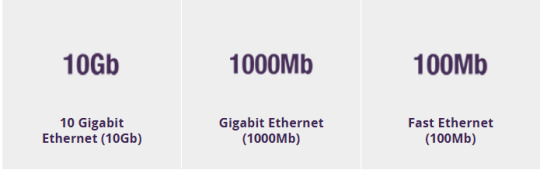
Ethernet network speeds have evolved significantly over time and typically range from Ethernet (802.11) at 10Mbps, Fast Ethernet (IEEE 802.3u) at 100Mbps, Gigabit Ethernet (IEEE 802.3-2008) at 1000Mbps and 10 Gigabit Ethernet (IEEE 802.3a) at 10Gbps. Meanwhile, Ethernet switches have also escalated from 10/100Mbps switch to Gigabit switch, 10GbE switch, and even 100GbE switches. The topic came up frequently that “Do I Need a Gigabit Switch or 10/100Mbps Switch?” Gigabit switch vs 10/100Mbps switch, which do I need to satisfy my network speeds requirement? This post will give you the answer.
Gigabit Switch: the Mainstream on Network Switch Market
A Gigabit switch is an Ethernet switch that connects multiple devices, such as computers, servers, or game systems, to a Local Area Network (LAN). Small business and home offices often use Gigabit switches to allow more than one device to share a broadband Internet connection. A gigabit switch operates in the same manner, only at data rates much greater than standard or Fast Ethernet. People can use these switches to quickly transfer data between devices in a network, or to download from the Internet at maximum speeds of 1000Mbps. If a switch says “Gigabit", it really means the same thing as 10/100/1000, because Gigabit switches support all three speed levels and will auto-switch to the appropriate one when something is plugged in. The following is a Gigabit 8 port poe switch with 8 x 10/100/1000Base-T RJ45 Ethernet ports.

10/100Mbps Switch: Still Alive and Well for Some Reason
10/100Mbps switch is a Fast Ethernet switch released earlier than Gigabit Ethernet switch. The data speed of 10/100Mbps switch is rated for 10 or 100Mbps. When a network switch says "10/100", it means that each port on the switch can support both 10Mbps and 100Mbps connection speeds, and will usually auto-switch depending on what's plugged into it. Currently, few devices run at 10Mbps, but it is still alive on the market for some reason. Actually, 10/100 is sufficient for internet browsing and Netflix. But if you will be doing more than one thing with your network connection, such as file transfers, or the set-top box, I would recommend you go with the Gigabit switch.

Gigabit Switch vs 10/100Mbps Switch: How to Choose?
Network engineers who refresh the edge of their campus LAN encounter a fundamental choice: Stick with 100Mbps Fast Ethernet or upgrade to Gigabit Ethernet (GbE). Vendors will undoubtedly push network engineers toward pricier GbE, but network engineers need to decide for themselves which infrastructure is right for the business. Currently, Gigabit switch is much more popular than Fast Ethernet 10/100Mbps switch. Because gigabit switch used in tandem with a gigabit router will allow you to use your local network at speeds up to ten times greater than 10/100Mbps switch. If either of these component are not gigabit, the entire network will be limited to 10/100 speeds. So, in order to use the maximum amount of speed your network can pump out, you need every single component in your network (including you computers) to be gigabit compliant. In addition, by delivering more bandwidth and more robust management, Gigabit switches are also more energy efficient than 10/100Mbps switches. This offers enterprises the opportunity to lower their power consumption on the network edge.
Conclusion
There’s a multitude of switch options to choose from on the dazzling market. So, before determining the right switch for your network, you’re supposed to have a close look at your current deployment and future needs. But for most cases, we recommend you buy Gigabit Ethernet devices instead of Fast Ethernet devices, even if they cost a little bit more. FS provides a full set of Gigabit switches, including 8 port switch, 24 port switch, 48 port switch, etc. With these high performance Gigabit Ethernet switches, your local network will run faster with better internet speed.
Originally published at http://www.fiber-optic-tutorial.com/gigabit-switch-vs-10-100mbps-switch.html
0 notes
Text
TAP Aggregation Switch: Key to Monitor Network Traffic
For network professionals, Ethernet switches have already been used very commonly in network design. In order to ensure network security and monitor the performance of the standard Ethernet switches, network test access port (TAPs) have emerged as one of the primary sources for data monitoring or network traffic monitoring. What is network TAP or TAP aggregation switch, and how to deploy it for network traffic monitoring? This post will give you the answer.
What Is TAP Aggregation Switch or Network TAP?
A network tap is a hardware device which provides an approach to access the data flowing across a network. It functions by flow copy or aggregation, thus it’s also called TAP aggregation switch. TAP aggregation switch works by designating a device to allow the aggregation of multiple TAPs and to connect to multiple monitoring systems. In this process, all the monitoring devices are linked to specific points in the network fabric that handle the packets that need to be observed. In most cases, a third party TAP aggregation switch monitors the traffic between two points in the network. If the network between point A and B consists of a physical cable, a network TAP or TAP aggregation switch might be the best way to accomplish this monitoring. TAP aggregation switch deployed between point A and B passes all traffic through unimpeded, but it also copies that same data to its monitor port, which could enable a third party to listen.
Deployment Scenario of TAP Aggregation Switch
TAP aggregation switches or network TAPs can be extremely useful in monitoring traffic because they provide direct inline access to data that flows through the network. The following part illustrates the typical applications of TAP aggregation switches in data center and carrier network.
Application in Data Center
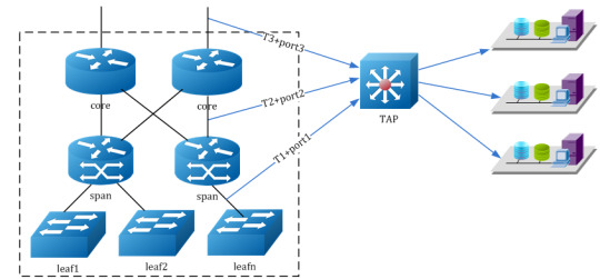
As shown in the figure below, user can enable the timestamp and source port label function of TAP devices. The server cluster can access the exact packet process time in each data center layer via source port and timestamp message carried by the packets. From port1, port2, port3, user can distinguish the devices that the streams come from. Through T1, T2 and T3, packets forward latency of each device can be calculated, according to which users can find out the bottleneck during packet forwarding for the further optimization of data center network.
Application in Carrier Network
TAP aggregation switch can also be used to assist DPI (Deep Packet Inspection) in carrier networks. As illustrated below, TAP aggregation switch is applied to forward flows of carrier at internet access point and sends a mirrored copy of the packet flow to DPI device at the same time. The DPI device is for traffic analysis, once a virus on website or illegal information has been monitored, the flows will be blocked by a five elements table sent from management channel between DPI and TAP.

Conclusion
TAP aggregation switches are crucial to any network monitoring plan because they offer an uncensored view of all network traffic. With FS TAP aggregation switches, customers can transform opaque data center traffic into comprehensive visibility for security threat detection, service availability monitoring as well as traffic recording and troubleshooting. Apart from TAP aggregation switches, the standard Ethernet switches including Gigabit switches, 10gb switches, 40gb switches and 100gb switches are also available for your choice.
Originally published at http://www.fiber-optic-tutorial.com/tap-aggregation-switch-monitor-network-traffic.html
0 notes
Text
What Is SFP Connector, SFP+ Connector and SFP28 Connector?
SFP (Small Form-factor Pluggable) module connector with various data speed rate is one of the major optical transceivers used for data communication. With ever-increasing demand for faster speed and higher density, the SFP connectors have experienced several generations of update for the signal speed capability as well as port density, from the original SFP to SFP+ and then to the new SFP28 type. The compatibility of these connecting ports is the pain point for many subscribers in data communication transmission. So what’s the similarities and differences between them and are these module connectors compatible with each other when plugged into switches? SFP28 vs SFP+ vs SFP connector, which one should you choose? This paper will give you the answer.
What Is SFP Connector?
Specified by a multi-source agreement (MSA), SFP connector was first introduced in early 2000 and designed to replace the previous gigabit interface converter (GBIC) connector in fiber optic and Ethernet high-speed networking systems. Based on the IEEE 802.3, SFF-8472 protocol specification, SFP module connectors has the ability to handle up to 4.25Gb/s with greater port density than the GBIC, which is why SFP is also known as mini GBIC. This allowed it to quickly become the connector of choice for system administrators who liked the idea of being able to significantly increase their output per rack. The SFP connectors can support Gigabit Ethernet, Fibre Channel, Synchronous Optical Network (SONET) and other communication standards.
What Is SFP+ Connector?
To cater the need for faster transmission speed, the SFP+ (or SFP10) was introduced in 2006, as an extension of the SFP connector. Based on IEEE802.3ae, SFF-8431, and SFF-8432 protocol specifications, the SFP+ is designed to support data rates up to 10Gb/s. Compared with its predecessor SFP, the newly SFP+ can support Fibre Channel, 10GbE, SONET, OTN, and other communication standards. The SFP+ is similar in size to the SFP connector. And the primary difference between an SFP and a SFP+ is their transmission speed. It is noticeable that SFP/SFP+ are both copper and optical.

SFP28 Connector–The Third Generation of SFP Connector
As the third generation of SFP interconnect systems, the SFP28 (Small Form-Factor Pluggable 28) is designed for 25G performance specified by the IEEE 802.3by. The SFP28 connector delivers increased bandwidth, superior impedance control with less crosstalk compared to the SFP10. SFP28 can be sorted into SFP28 SFP-25G-SR and SFP-25G-LR. The former is designed to transfer data over short distance (up to 100m over MMF) while the latter is suitable for long distance transmission (up to 10 km over SMF). Utilizing 25GbE SFP28 leads to a single-lane connection similar to existing 10GbE technology, however it can deliver 2.5 times more data, which enables network bandwidth to be cost-effectively scaled in support of next-generation server and storage solutions.
Are the SFP, SFP+ and SFP28 Products Backward Compatible?
In most cases the connector and cable assembly are all backward compatible – an SFP+ connector is a direct replacement for an SFP connector to ensure simple upgrade to customer systems. As these are standard products, the cable assembly will also be compatible between the systems – an SFP copper cable assembly can be inserted to an SFP+ cage and mate with a SFP+ connector on the board.
Then how about the new SFP28 product? Since transceivers with various SFP connector types have become an important constituent of data communication network, compatibility issue of SFP28 and SFP+ is controversial among many subscribers. Here is a typical topic from Reddit, and it says like “For a project we’re looking to purchase some nexus 93180YC-EX ToRs for 25Gb+ down to the compute nodes. Cisco states that the downlink 25Gb ports are also 10Gb capable, but one can only really assume that means that the port is compatible with SFP+ optics too. Cisco’s SFP+ compatibility matrix appears to support that claim, however just curious if any of you have any SFP28 experience yet to confirm?”
The answer is definitely “yes”. SFP28 adopts the same form factor as SFP+, just running at 25 Gb/s instead of 10Gb/s, which offers better performance and higher speed. Besides, the pinouts of SFP28 and SFP+ connectors are mating compatible. Therefore, SFP28 connector is backwards compatible with SFP+ ports. That is to say, an SFP28 can be plugged into an SFP+ port and vice versa, but plugging an SFP+ into an SFP28 port would not get you 25Gb/s data rates.
Conclusion
SFP28 vs SFP+ vs SFP connector? Have you made clear which one to choose? Whether choosing SFP or SFP+ depends on your switch types. If your switch port only supports 1G, you can only choose the 1000BASE SFP (eg.MGBSX1). If it is a 10G switch, it depends on the speed and distance you require. When choosing between SFP28 and SFP+, it all depends on the transmission data rates you need. The SFP28 aims to build 25GbE networks that enables equipment designers to significantly reduce the required number of switches and cables. Thus when considering reduced facility costs related to space, power and cooling, the SFP28 would be the optimal choice for you.
Originally published at http://www.fiber-optic-tutorial.com/sfp-connector-sfp-connector-sfp28-connector.html
0 notes
Text
DWDM Solutions for Arista 7500E Series Switches
Nowadays, the deployment of DWDM solution has been hotly debated in many enterprise networks, especially in the new Lay2 and Lay3 equipment like Arista 7500E series switches. For many enterprises, DWDM network solutions are undoubtedly the best choices of action, because they can provide a scalable and elastic solution for the enterprise that offered high bandwidth and data separation. This article will demonstrate DWDM solutions to Arista 7500E switches which are the foundation of two-tier open networking solutions for cloud data centers.
Analysis of DWDM System
DWDM (Dense Wavelength Division Multiplexing) is a technology allowing high throughput capacity over longer distances commonly ranging between 44-88 channels and transferring data rates from 100 Mbps up to 100 Gbps per wavelength. For intra-datacenter solutions, an endpoint connection often uses multimode (850 nm) for short ranges and single mode (1310 nm) for longer ranges. The DWDM node converts this local connection to a channelized frequency or wavelength, which is then multiplexed with other wavelength and transmitted over a single fiber connection.
A key advantage of DWDM is that it’s bitrate independent. DWDM-based networks can transmit data in IP, ATM, SONET, SDH and Ethernet. Therefore, DWDM systems can carry different types of traffic at different speeds over an optical channel. Voice transmission, email, video and multimedia data are just some examples of services which can be simultaneously transmitted in DWDM systems.
Arista 7500E 100G DWDM Line Card
With full support for Layer2 and Layer3 protocols, Arista 7500E series switch is the ideal option for the network spine for two tier data centers applications. Arista 7500E especially provides the perfect resolution for high bandwidth Metro and long-haul DCI solutions with the 6-port DWDM line card. It has great advantage to migrate from existing 10G DWDM to 100G coherent line side modules. The 7500E series DWDM line card provides six 100G ports with coherent 100G tunable optics, which enables customers to connect directly into existing WDM MUX module without the need to add transceivers, which can save cost and space to a large extent. The coherent optics use C-band region wavelengths and offer a cost efficient solution for up to 96 channels of 100Gb over a single dark fiber pair.
Use Cases for Arista 7500E DWDM Card
Less Than 80 km Dark Fiber Connection For distance less than 80 km, Arista 7500E switch with DWDM line cards can directly terminate a dark fiber connection with a pair of passive DWDM Mux, thus achieving a point-to-point connection between two locations.
Between 80 km and 150 km Connection For distance greater than 80 km but less than 150 km, losses occurred during the process of transmission should be considered. In order to boost the power level, an EDFA (Erbium Doped Fiber Amplifier) is used to gain flatness, noise level, and output power, which is typically capable of gains of 30 dB or more and output power of +17 dB or more. With the use of EDFA, the signal can be boosted into a certain power level, thus achieving distances of up to 150 km.
Conclusion
The Arista 7500E series DWDM solution offers a cost-effective solution for transporting scalable and massive volumes of traffic, and enhances the 7500E system by providing high performance 100G DWDM port density with the same rich features and dedicated secure encryption in compact and power-efficient systems. Enterprises can easily migrate existing metro and long-haul DWDM networks to add new 100G capacities, thus expanding Layer2 and Layer3 services.
Originally published at http://www.china-cable-suppliers.com/dwdm-solutions-arista-7500e-series-switches.html
0 notes
Text
Difference Between AON and PON
AON (Active Optical Networks) and PON (Passive Optical Network) serve as the two main methods of building CWDM and DWDM backbone network. Each of them has their own merits and demerits. This article will compare them according to their different features and applications.
AON
An active optical system uses electrically powered switching equipment, such as a router or a switch aggregator, to manage signal distribution and direction signals to specific customers. This switch directs the incoming and outgoing signals to the proper place by opening and closing in various ways. In such a system, a customer may have a dedicated fiber running to his or her house. The reliance of AON on Ethernet technology makes interoperability among vendors easy. Subscribers can select hardware that delivers an appropriate data transmission rate and scale up as their needs increase without having to restructure the network. However, AON require at least one switch aggregator for every 48 subscribes. Since it requires power, an active optical network inherently is less reliable than a passive optical network.
PON
A PON is made up of an optical line termination (OLT) at the service provider’s central office and a number of optical network units (ONUs) near end users. Typically, up to 32 ONUs can be connected to an OLT. The passive optical network simply describes the fact that optical transmission has no power requirements or active electronic parts once the signal is going through the network.
A PON system makes it possible to share expensive components for FTTH. A PON splitter takes one input and splits it to broadcast to many users, which can lower the cost of the links substantially by sharing, for example, one expensive laser with up to 32 homes. PON splitters are bi-directional, that is signals can be sent downstream from the central office, broadcast to all users, and signals from the users can be sent upstream and combined into one fiber to communicate with the central office.

A passive optical network does not include electrically powered switching equipment. It uses optical splitters to separate and collect optical signals as they move through the network. A PON shares fiber optic strands for portions of the network. Powered equipment is required only at the source and receiving ends of the signal. PONs are efficient since each fiber optic strand can serve up to 32 users. Besides, PONs have a low building cost compared with active optical networks along with lower maintenance cost. However, PONs also have some demerits. They have less range than an AON, which means subscribes must be geographically closer to the central source of the data. When a failure occurs, it is rather difficult to isolate it in a PONs. Moreover, because the bandwidth in a PON is not dedicated to individual subscribers, data transmission speed may slow down during peak usage times in an effect known as latency. And latency would quickly degrade services such as audio and video, which need a smooth rate to maintain quality.
AON vs. PON
As early as the year 2009, PONs began appearing in corporate networks. Users were adopting these networks because they were cheaper, faster, lower in power consumption, easier to provision for voice, data and video, and easier to manage, since they were originally designed to connect millions of homes for telephone, Internet and TV services.
Passive Optical Networks (PON) provide high-speed, high-bandwidth and secure voice, video and data service delivery over a combined fiber network. The main benefits of PON are listed below:
Lower network operational costs
Elimination of Ethernet switches in the network
Elimination of recurring costs associated with a fabric of Ethernet switches in the network
Lower installation (CapEx) costs for a new or upgraded network (min 200 users)
Lower network energy (OpEx) costs
Less network infrastructure
You can reclaim wiring closet (IDF) real estate
Large bundles of copper cable are replaced with small single mode optical fiber cable
PON provides increased distance between data center and desktop (>20 kilometers)
Network maintenance is easier and less expensive
Fiber is more secured than copper. It is harder to tap. There is no available sniffer port on a passive optical splitter. Data is encrypted between the OLT and the ONT.
Conclusion
To sum up, the PON network’s predefined topology makes individual changes more difficult. By terminating all the fiber optics at the OLT, i.e. the same fiber optic topology as in the AON (point-to-point), this disadvantage can be overcome. Therefore, for future-proof infrastructure investment, reliable point-to-point fiber optics technology should always be considered.
0 notes
Text
Using EDFA Amplifier for Long-Haul CATV Systems
With Laser technology combining with fiber optic technology, CATV systems in the field of optical communication have demonstrated unprecedented and irreplaceable achievements in the past few decades. When transmitting optical signals with fibers, fiber attenuation is the main factor that limits the transmission distance. EDFA (Erbium-Doped Fiber Amplifier) designed for CATV long-haul transmission avoids the conversion of optic-electric-optic in CATV long-haul transmission. It amplifies low signal power into high signal power, thus extending transmission distance. This post analyzes EDFA configurations and the utilization in long-haul CATV systems.
EDFA Leading Position in CATV Systems
EDFA is one of the most prominent achievements in fiber optic transmission technology over the past decade. Because it cleverly combined the laser technology and optical fiber manufacturing technology in the CATV systems and its applications were then rapidly expanded. Originally PDFA and EDFA amplifiers were equally used for CATV systems, but today, EDFA has completely replaced PDFA and become the primary device for fiber optic transmission systems. Why EDFA has leading position on CATV systems? Because EDFA noise and distortion characteristics are better, and its superior characteristics can be clearly seen in the following:
Operates at wavelength of 1550nm, consistent with C-band where fiber has the lowest loss
Has higher saturation output power, useful in systems requiring transmission up to 100 km or systems requiring the optical signal to be split to multiple fiber optic receivers
The signal gain spectrum is wide up to 30nm or more, can be used for broadband signal amplification, especially for WDM (wavelength division multiplexing) system, ideal for radio and data services networks
Has user friendly interface RS232, easy to control and monitor with computers
Low noise figure with high stability
EDFA Configurations
The configuration of a co-propagating EDFA is shown in Figure 1. The optical pump is combined with the optical signal into the erbium-doped fiber with a wavelength division multiplexer. A second multiplexer removes residual pump light from the fiber. An in-line optical filter provides additional insurance that pump light does not reach the output of the optical amplifier. An optical isolator is used to prevent reflected light from other portions of the optical system from entering the amplifier.

An EDFA with a counter propagating pump is pictured in Figure 2. The copropagating geometry produces an amplifier with less noise and less output power. The counter propagating geometry produces a noisier amplifier with high output power. A compromise can be made by combining the co- and counter-propagating geometries in a bi-directional configuration.

A Typical CATV System Using EDFA
Figure 3 illustrates a basic long-haul CATV transmission system designed to carry 77 channels of CATV signals for 100 km in a basic point-to-point configuration.
As you can see in Figure 3, the local CATV provider sends 77 channels of CATV signals at the transmitting side. After processing and RF combining, those multiple signals are combined into one channel of CATV signal with the wavelengths of 1550 nm. It transmits over a single-mode optical fiber to 50 km. An EDFA amplifier is used at the middle point to amplify the signals to a certain power level, continuing to transmit over a single mode fiber to 100 km. At the receiving side, the 1550nm CATV channel is split into multiple channels of 1550nm CATV signals, serving multiple hotel cable TV users.
FS.COM CATV EDFA Optical Amplifiers List
EDFA has undoubtedly received wide interest for CATV applications because of its high output power, low distortion and low noise capability. FS.COM supplies optical amplifiers including CATV EDFA, SDH EDFA, DWDM amplifier, etc. The following table lists FS.COM CATV EDFA amplifiers which are available with range of output power from 13 dBm to 24 dBm to meet the requirements of a high-density solution for the large-scale distribution of broadband CATV video and data signals to video overlay receivers in a FTTH/FTTP or PON system.

Originally published at: http://www.china-cable-suppliers.com/using-edfa-amplifier-long-haul-catv-systems.html
0 notes
Text
CWDM and DWDM Network Solutions
Growing demands of the internet users is one of the reasons that lead using wavelength division multiplexing (WDM) networks to transmit optical data. So, what is WDM? WDM is a technology that multiplexes various optical signals through a single optical fiber by taking advantage of different wavelengths of laser light. And the ITU-T recommendation specifies the wavelengths used in CWDM/DWDM or OADM. All the passive fiber optic components are made of filters that only allow specific wavelength to pass through a fiber port and then the others to be reflected to another fiber ports.
WDM Network Overview
A WDM network uses a multiplexer at the transmitter to join the several signals together, and a demultiplexer at the receiver to split them apart. With the increasing demand of data, video and mobile usage on many networks, WDM technology has proved to be the most reliable and cost-effective in transporting large amount of data in telecom. And by utilizing CWDM and DWDM network systems to scale the bandwidth, the operators enable to transmit service from 2Mbps up to 100Gbps of data. Now WDMs are very popular in field of CATV, Internet, VoIP, audio and video solutions, and even bring FTTX solutions to the people’s daily life.
CWDM Network Solutions
CWDM stands for Course Wavelength Division Multiplexer. “Course” means the channel spacing is 20nm with a working channel pass band (±6.5nm or ±7.5nm) from the wavelengths center. CWDM MUX DEMUX Modules take advantage of conventional thin-film filter (TFFS) technology and that allow various channels within ITU G.694 Grid (1270nm~1610nm,1271nm~1611nm), to realize multiplexing or demultiplexing wavelengths over one fiber. Due to the use of cheaper CWDM uncooled laser or lower-quality multiplexer and demultiplexers without fiber amplifiers. The CWDM works at a 60 or 80 km transmission with the wavelength of 1550nm. So CWDM is a very attractive options in metro networks.
DWDM Network Solutions
DWDM stands for Dense Wavelength Division Multiplexer. The word “Dense” is referring to the very narrow channel spacing measured in Gigahertz (GHz) as opposed to nanometer (nm). DWDM us typically use channel spacing measured in GHz (100G or 200G, C-Band 1525nm~1565nm). Now an optical fiber inter-leaver or optic fiber chip is used to double the channel of 100GHz or 200GHz spacing, that’s 50GHz or 100GHz AWG. Just like CWDM MUX DEMUX, DWDM MUX DEMUX also takes the advantage of thin-film filters and are used to increase the amount of data capacity that can be transmitted over a single fiber. The DWDM will be with more channels with much tighter channel spacing. Typical DWDM MUX DEMUX modules only have 32, 40, 44 channels but today’s 50Ghz 100Ghz DWDM MUX DEMUX doubles the channel spacing and can reach up to 64, 80, 88 and even 90 channels.

DWDM is the most suitable technology for long-haul transmission because of its ability to allow EDFA amplification. Given the growing need for bandwidth driven by data-hungry applications (smartphones, video streaming, etc.), DWDM has now found its way into metro networks, and is even being used in some cellular back-haul deployments.
Conclusion
WDM systems have become one of the major solutions to meet the growing demand for increased network bandwidth brought about by the rapid growth of Internet and data services. CWDM and DWDM network solutions have their own suitable applications. If you want to get more details for these solutions, kindly visit www.fs.com.
0 notes
Text
Necessary Components in DWDM Systems
DWDM (Dense Wavelength Division Multiplexing) is used to increase the amount of information or systems that can be transmitted over a single fiber, thus allowing allow for more channels with much tighter channel spacing. In DWDM systems, DWDM devices combine the output from several optical transmitters for transmission across a single optical fiber. At the receiving end, another DWDM device separates the combined optical signals and passes each channel to an optical receiver. This article covers DWDM system components that combine (multiplex) and separate (demultiplex) multiple optical signals of different wavelengths in a single fiber.
Optical Transmitters/Receivers
As the light sources in a DWDM system, the optical transmitters are of great importance to the whole system design. In DWDM systems, multiple transmitters are used to provide the source signals which are then multiplexed. Incoming electrical data bits (0 or 1) trigger the modulation of a light stream (e.g., a flash of light = 1, the absence of light = 0). Lasers create pulses of light, each with an exact wavelength. In an optical-carrier-based system, a stream of digital information is delivered to a physical layer device, whose output is a light source (an LED or a laser) that interfaces a fiber optic cable. Then the device converts the incoming electrical signals to optical form signals. Electrical ones and zeroes trigger a light source that flashes light into the core of an optical fiber. The format of the underlying digital signal is not changed. Pulses of light propagate across the optical fiber by total internal reflection. At the receiving end, another optical sensor (photodiode) detects light pulses and converts the incoming optical signals back to electrical signals. Two fibers are used in this process, one for transmitting and the other for receiving.
DWDM Mux/DeMux Modules
The DWDM Mux combines multiple wavelengths created by multiple transmitters and operating on different fibers. The output signal of an multiplexer is referred to as a composite signal. At the receiving end, the DeMux (demultiplexer) separates all of the individual wavelengths of the composite signal out to individual fibers. The individual fibers pass the demultiplexed wavelengths to as many optical receivers. Generally, Mux and DeMux components are contained in a single enclosure. Optical Mux/DeMux devices can be passive. Component signals are multiplexed and demultiplexed optically, not electronically, therefore no external power source is required.

Optical Add/Drop Multiplexers (OADM)
In a DWDM system, the optical add/drop multiplexers (OADM) can add or drop DWDM channels into an existing backbone ring. It provides the ability to drop one DWDM channel from the network fiber, while allowing all other channels to continue pass to other nodes. Similarly, the drop/insert module removes an individual channel from the network fiber, however, it also provides the ability to add that same channel back onto the network fiber.
Optical Fiber Amplifiers
Optical fiber amplifiers boost the amplitude or add gain to optical signals passing on a fiber by directly stimulating the photons of the signal with extra energy. Optical fiber amplifiers amplify optical signals across a broad range of wavelengths. They can provide flat gain over a large dynamic gain range, have a high saturated output power, low noise, and effective transient suppression. Erbium-doped fiber amplifier (EDFA) is the most widely used fiber amplifier which has received great attention over the past 10 years. EDFA is generally used for very long fiber links such as undersea cabling. It uses a fiber that has been treated or "doped" with erbium, and this is used as the amplification medium.
Transponders (OEO)
Transponders are also referred to as optical-electrical-optical (O-E-O) wavelength converters. They can convert optical signals from one incoming wavelength to another outgoing wavelength suitable for DWDM applications. A transponder performs an O-E-O operation to convert wavelengths of light. Within the DWDM system, a transponder converts the client optical signal back to an electrical signal (O-E) and then performs either 2R (reamplify, reshape) or 3R (reamplify, reshape and retime) functions.

Conclusion
With all the necessary components, DWDM-based networks can transmit data in IP, ATM, SONET, SDH and Ethernet. Therefore, DWDM-based networks can carry different types of traffic at different speeds over an optical channel. If you want to learn more about all these components for DWDM system, kind visit www.fs.com for more details.
0 notes
Text
Evolution of Optical Wavelength Bands
As fiber optic networks have developed for higher speeds, longer distances, and wavelength-division multiplexing (WDM), fibers have been used in new wavelength ranges, namely "bands". Fiber transmission bands have been defined and standardized, from the original O-band to the U/XL-bands. This article will mainly illustrate the evolution of the typical fiber transmission bands used for different optical telecom systems.
Among these bands, the O-band, also called the Original-band, was the first band used in optical telecommunication because of the small pulse broadening (small dispersion); Single-mode fiber transmission began in the "O-band" just above the cutoff wavelength of the SM fiber developed to take advantage of the lower loss of the glass fiber at longer wavelengths and availability of 1310nm diode lasers.
The E-band represents the water peak region while the U/XL-band resides at the very end of the transmission window for silica glass. The E-band (water-peak band) has not yet proven useful except for CWDM. It is probably mostly used as an extension of the O-band but few applications have been proposed and it is very energy-intensive for manufacture. The E-band and U/XL-bands usually are avoided because they correspond to high transmission loss regions.
To take advantage of the lower loss at wavelength of 1550nm, fiber was then developed for the C-band. The C-band is commonly used along with the development of ultra-long distance transmission with EDFA and WDM technologies. As transmission distances became longer and fiber amplifiers began being used instead of optical-to-electronic-to-optical repeaters, the C-band became more important. With the advent of DWDM (dense wavelength-division multiplexing) which enables multiple signals to share a single fiber, the use of C-band was expanded.
With the development of fiber amplifiers (Raman and thullium-doped), DWDM system was expanded upward to the L-band, leveraging the wavelengths with the lowest attenuation rates in glass fiber as well as the possibility of optical amplification. Erbium-doped fiber amplifiers (EDFAs, which work at these wavelengths) are a key enabling technology for these systems. Because WDM systems use multiple wavelengths simultaneously, which may lead to much attenuation. Therefore optical amplification technology is introduced.
Despite great expectations, the number of installed systems using all-Raman solutions worldwide can be counted on one hand. In the future, however, the L-band will also prove to be useful. Because EDFAs are less efficient in the L-band, the use of Raman amplification technology will be re-addressed, with related pumping wavelengths close to 1485nm.
Although CWDM is now considered as a low-cost version of WDM that has been in use, most do not work over long distances. The most popular is FTTH PON system, sending signals downstream to users at 1490nm (in S-band) and using low cost 1310nm transmission upstream. Early PON systems also use 1550 downstream for TV, but that is being replaced by IPTV on the downstream digital signal at 1490nm. Other systems use a combination of S, C and L bands to carry signals because of the lower attenuation of fibers. Some systems even use lasers at 20nm spacing over the complete range of 1260nm to 1660nm but only with low water peak fibers.
Although various wavelength bands of the O-, S-, C- and L- bands have come into use with the explosive expansion of the traffic in recent years, the optical fiber amplifiers for the O- and S-band wavelengths were not realized for many years because of many technical hurdles. C- and L-band most commonly used in fiber optic networks will play more and more important roles in optical transmission system with the growth of FTTH applications.
Originally published at http://www.china-cable-suppliers.com
0 notes