#WDM MUX
Explore tagged Tumblr posts
Visit Tumblr Blog
Explore Tumblr blogs with no restrictions, modern design and the best experience.
Last Seen Tumblr Blogs


Fun Fact
Hackers stole 65M passwords from Tumblr in 2013.
Text
Rollball, established in 2000 and based in Shenzhen, China, is a leading provider of high-performance fiber optic communication products and accessories for telecommunications, broadcast, CATV, and network industries worldwide.
Pioneering Optical Transceiver Technology
As one of the early pioneers in China, Rollball has successfully developed a comprehensive range of optical transceiver modules, including XFP, X2, XENPAK, SFP+, SFP, DWDM SFP, and GBIC series. These modules are widely compatible with Ethernet, SDH/SONET, SAN, and video monitoring applications. Our products are renowned for their exceptional performance, reliability, and competitive pricing.
Precision-Engineered Cable Assemblies
Our fiber optical cable assemblies, including fiber patch cords and pigtails, are meticulously crafted to ensure optimal performance. We adhere to strict quality control standards, testing each patch cord to guarantee its quality. We offer a wide range of connectors, including SC, ST, FC, LC, MU, MTRJ, DIN, D4, and MPO, and can customize cable lengths to meet specific customer requirements.
Quality and Customer Satisfaction
At Rollball, quality is our top priority. We are ISO 9001:2000 certified and maintain rigorous quality control processes, from supplier evaluation to final shipment. Our dedicated team is committed to providing exceptional customer service, delivering high-quality fiber optic products on time, and helping our customers achieve their business goals.
Experience the Rollball Difference
By choosing Rollball, you're choosing a reliable partner that delivers innovative solutions, superior quality, and outstanding customer support.
0 notes
Video
youtube
Small size 8CH CWDM Mux Module #cwdm #dwdm #wdm #
#youtube#Small 8CH CWDM Mux: less capacity but enhances fiber network capacity low loss high isolation ideal for space-constrained environments.
0 notes
Text
1 note
·
View note
Text
WDM Mux/Demux Transmission Modes Overview
WDM (wavelength division multiplexing) is one of the technologies which can expand the capacity of a fiber optic network without requiring additional fiber, and it plays a very important role in long-haul data transmissions. In a WDM system, there is an important component called WDM Mux Demux (multiplexer/demultiplexer), which can multiplex multiple wavelengths into one single fiber to increase the network capacity. Usually, there are three transmission modes in WDM networks: duplex bi-directional transmission, simplex bi-directional transmission and simplex uni-directional transmission. And this post will illustrate some detailed information about three transmission modes of WDM Mux/Demux.
Duplex Bi-directional Transmission Mode
In this transmission mode, one fiber only transmits one direction optical signal and the reverse optical signal will be sent by another fiber, which is often seen in dual fiber WDM Mux/Demux. And the same wavelengths can be used in two directions. Take the 4CH dual fiber DWDM Mux/Demux for example, the transmit side and receive side of the WDM Mux/Demux are using the same wavelength C21, C22, C23 and C24. And this transmission mode can make full use of the huge bandwidth resources of the optical fiber, and the transmission capacity of one optical fiber is expanded. In the long-distance network, the number of wavelengths can be gradually increased according to the actual traffic volume, which is very flexible.

Simplex Bi-directional Transmission Mode
In this transmission mode, the simultaneous transmission of optical signals in two reverse directions will be realized in one fiber, which can greatly save fiber resources compared with duplex bi-directional transmission mode. This transmission mode are used in transmission between two dual fiber WDM Mux/Demux. The simplex bi-directional link has different wavelengths on the same channel, so single fiber Mux/Demux are always used in pairs. Take the 4CH single fiber DWDM Mux/Demux for example, the transmit wavelength of the client port at side-A (the left side) must match the receive wavelength of the same client port at side-B (the right side). As for the wavelength of the transceiver, it is mainly based on the transmit wavelength of the client port.

Simplex Uni-directional Transmission Mode
Simplex uni-directional transmission means that an optical fiber only transmits optical signals in one direction, and there is no reverse optical signal. The Mux multiplexes the wavelengths at one side, and the Demux demultiplexes the wavelengths at the other side, just like the following picture shown. we can see that wavelengths of the DWDM Mux Demux at the left and right ends are the same. This transmission mode is less popular in the current market because duplex bi-directional and simplex bi-directional transmission modes have the same function of this transmission mode.

FAQs About Three Transmission Modes
1. Does single fiber Mux support simplex uni-directional transmission?
Compared with Mux and Demux in uni-directional transmission (they just multiplex or demultiplex the wavelengths), the single fiber WDM Mux/Demux in the current market can multiplex and demultiplex the wavelengths, which can realize uni-directional transmission.
2. How many channels at maximum will be made for CWDM Mux/Demux and DWDM Mux/Demux respectively in different transmission modes?
In FS, in terms of CWDM Mux/Demux
·Duplex bi-directional: up to 18 channels
·Simplex bi-directional: up to 9 channels
·Simplex uni-directional: up to 18 channels
In FS, in terms of DWDM Mux/Demux
·Duplex bi-directional: up to 40 channels
·Simplex bi-directional: up to 20 channels
Conclusion
In summary, you are more likely to have a general idea about three transmission modes of WDM Mux/Demux. WDM Mux/Demux in FS can expand existing fiber capacity and let operators make full of use of available fiber bandwidth, which will be a cost-effective, flexible solution for operators.
0 notes
Text
Choose the Right SFP+ Transceivers for CWDM Mux Demux
Nowadays, CWDM technology is very popularly used as a easy and economical way to extend the network capacity by carrying several signals with different wavelengths through a signal fiber. If your network capacity is not enough for your daily use, deploying a CWDM system is an ideal choice for you. As the CWDM Mux Demux should be finally linked with the switches in a completed CWDM system, the fiber patch cable and 10G CWDM SFP+ transceiver are required to finish the whole CWDM link. Hence, this paper will mainly introduce the CWDM Mux Demux and choose the right CWDM SFP+ transceivers for the CWDM Mux Demux, which may be helpful for you to fast build a CWDM system.
CWDM Mux Demux–Key Component for CWDM System
CWDM Mux Demux is a key component for CWDM system, which should work in pairs. As an optical module, it can act as a multiplexer or demultiplexer at either end of the fiber cable. This kind of optical Mux Demux is much easier to use than the DWDM Mux Demux, but can not support the network as long as that of the DWDM Mux Demux. In general, it can offers several kinds of wavelengths, usually from 1270nm to 1610nm (20nm spacing), to support the signal transmission at lengths up to 80 km. Meanwhile, the CWDM Mux Demux can be designed with 4 channels, 8 channels, 9 channels, 16 channels and 18 channels for transmitting different amount of signals. To better know how does this kind of WDM Mux work, the following figure offers a reliable 4 channel CWDM Mux Demux duplex transmission design.

From the figure above, we can learn that two CWDM Mux Demux are connected by a length of duplex patch cable, and they are designed with four channels multiplexing the 1470nm, 1490nm, 1510nm and 1530nm over the same fiber. To complete the transmission link, four pairs of CWDM SFP+ transceivers with 1470nm, 1490nm, 1510nm and 1530nm TX and RX should be separately inserted into the ports of these two WDM Mux Demux. When the CWDM system works, the four different signals from the left to the right will be multiplexed in the CWDM Mux, transmitted over the duplex fiber and demultiplexed in the CWDM Demux, and vice versa for the signals from the right to the left.
How to Choose the CWDM SFP+ Transceivers for CWDM Mux Demux?
As mentioned above, the CWDM SFP+ transceivers are required for building a CWDM system which should be correctly inserted into the SFP+ ports of the CWDM Mux Demux. Thereby, here offers three factors that should be taken into consideration when choosing the CWDM SFP+ transceivers for the CWDM Mux Demux.
The first factor is the working wavelengths of the CWDM SFP+ transceivers. In order to ensure the CWDM system performance, the SFP+ transceiver working wavelengths should be the same to the SFP+ ports of the CWDM Mux Demux. Just like the first figure, when the working wavelengths of the first pair of CWDM SFP+ transceivers are 1470 nm, the first ports of the two CWDM Mux Demux should be also 1470 nm, so that the signal with 1470 nm can be successfully transmitted in the CWDM system. As the CWDM working wavelengths are available from 1270 nm to 1610 nm and the channel spacing is 20 nm, there are 18 kinds of working wavelengths for CWDM SFP+ transceivers, as shown in the following figure.

The second factor is the compatibility of the CWDM SFP+ transceivers. As the third party transceivers are more cost effective than the original one, the former kinds are always the choices for most users. However, the users are always unassured about the quality and compatibility of the third party transceivers for their low price. Here FS.COM is recommendable who offers the CWDM SFP+ transceivers fully tested on most famous original brand switches like Cisco, Brocade, Juniper and Arista. FS.COM CWDM SFP+ transceivers are less expensive but can perform as well as the original branded transceivers, without the compatible issue.
The third factor is the transmission distance the CWDM SFP+ transceivers can support. Although the CWDM system can not support the transmission as long as the DWDM one, it still can reach the lengths 80 km. At present, 10G CWDM SFP+ transceiver can be available at lengths of 20km, 40km, 60km, 80km or even longer on the market. Hence, you can also choose the CWDM SFP+ transceivers according to the transmission distance you system needs.
Conclusion
Building a CWDM system for carrying more data signals is a good choice if the existing network has insufficient capacity. To ensure the performance of the whole CWDM link, it is necessasry to choose the right CWDM SFP+ transceivers for the CWDM Mux Demux. From this paper, it can be concluded that there are mainly three factors, the working wavelength, the compatible issue and the transmission distance the CWDM SFP+ supports, should be taken into account when making the decision about which kind of CWDM SFP+ should be selected for the CWDM Mux Demux.
0 notes
Text
DWDM Solutions for Arista 7500E Series Switches
Nowadays, the deployment of DWDM solution has been hotly debated in many enterprise networks, especially in the new Lay2 and Lay3 equipment like Arista 7500E series switches. For many enterprises, DWDM network solutions are undoubtedly the best choices of action, because they can provide a scalable and elastic solution for the enterprise that offered high bandwidth and data separation. This article will demonstrate DWDM solutions to Arista 7500E switches which are the foundation of two-tier open networking solutions for cloud data centers.
Analysis of DWDM System
DWDM (Dense Wavelength Division Multiplexing) is a technology allowing high throughput capacity over longer distances commonly ranging between 44-88 channels and transferring data rates from 100 Mbps up to 100 Gbps per wavelength. For intra-datacenter solutions, an endpoint connection often uses multimode (850 nm) for short ranges and single mode (1310 nm) for longer ranges. The DWDM node converts this local connection to a channelized frequency or wavelength, which is then multiplexed with other wavelength and transmitted over a single fiber connection.
A key advantage of DWDM is that it’s bitrate independent. DWDM-based networks can transmit data in IP, ATM, SONET, SDH and Ethernet. Therefore, DWDM systems can carry different types of traffic at different speeds over an optical channel. Voice transmission, email, video and multimedia data are just some examples of services which can be simultaneously transmitted in DWDM systems.
Arista 7500E 100G DWDM Line Card
With full support for Layer2 and Layer3 protocols, Arista 7500E series switch is the ideal option for the network spine for two tier data centers applications. Arista 7500E especially provides the perfect resolution for high bandwidth Metro and long-haul DCI solutions with the 6-port DWDM line card. It has great advantage to migrate from existing 10G DWDM to 100G coherent line side modules. The 7500E series DWDM line card provides six 100G ports with coherent 100G tunable optics, which enables customers to connect directly into existing WDM MUX module without the need to add transceivers, which can save cost and space to a large extent. The coherent optics use C-band region wavelengths and offer a cost efficient solution for up to 96 channels of 100Gb over a single dark fiber pair.
Use Cases for Arista 7500E DWDM Card
Less Than 80 km Dark Fiber Connection For distance less than 80 km, Arista 7500E switch with DWDM line cards can directly terminate a dark fiber connection with a pair of passive DWDM Mux, thus achieving a point-to-point connection between two locations.
Between 80 km and 150 km Connection For distance greater than 80 km but less than 150 km, losses occurred during the process of transmission should be considered. In order to boost the power level, an EDFA (Erbium Doped Fiber Amplifier) is used to gain flatness, noise level, and output power, which is typically capable of gains of 30 dB or more and output power of +17 dB or more. With the use of EDFA, the signal can be boosted into a certain power level, thus achieving distances of up to 150 km.
Conclusion
The Arista 7500E series DWDM solution offers a cost-effective solution for transporting scalable and massive volumes of traffic, and enhances the 7500E system by providing high performance 100G DWDM port density with the same rich features and dedicated secure encryption in compact and power-efficient systems. Enterprises can easily migrate existing metro and long-haul DWDM networks to add new 100G capacities, thus expanding Layer2 and Layer3 services.
Originally published at http://www.china-cable-suppliers.com/dwdm-solutions-arista-7500e-series-switches.html
0 notes
Text
Company Profile
https://www.optical-sintai.com/company-profile.html

Guangzhou Sintai Communication Co., Ltd, which was founded in early 2013, is specialized in the optical transmission field with R&D, production, sales and customer service. And shortly after that our OTNS8600 optical transmission network system was brought to the market. Especially, we were the one of the first companies to provide 100G wavelength division products with professional solutions in the industry in 2015. We’ve been dedicated to providing optical transmission network systems and optical transmission optimization solutions and have become one of the top optical communication products manufacturers and service providers in China.
We are committed to providing integrated optical transport network systems and optical transport optimization solutions, and our products mainly contain the WDM/ OTN systems (10G/ 25G/ 40G/ 100G/ 200G WDM system, 5G fronthaul transmission WDM systems), optical amplifier system (OEO/ EDFA/ SOA), optical protection system (OLP/ OBP/ FMS), passive optical device (AWG/ CWDM/ DWDM MUX&DEMUX/ DCM/ Splitter) and optical transceivers (SFP/ SFP+/ SFP28/ QSFP+/ QSFP28/ CFP/ CFP2). They are widely used by telecom operators and private network industry customers, including ISP, electric power, IDC, education, transport, radio and television, network security, big data and cloud services, etc.
Our products have its patented technology through our independent R&D and won the authorized certification, such as the design patent certificate, software copyright register certificates and series of quality management and test certificates.
After years of development, our products and services have extended to various industries at home and abroad. Our company base is at Guangzhou with branches at North, Northwest and East China. And the establishment of brand advantage has promoted the construction of our international marketing network. The awareness of Sintai is continuously increasing in the key markets. Our overseas business has extended to Europe, Middle East, Southeast Asia, North America, South America, Africa and so on.
In order to support our increasing domestic and overseas markets, we have built professional production team, sales team, service team and R&D team to provide the industry-leading and comprehensive products. With many years’ experience of optical communication technology, we are focusing on optical transmission and optical device technology to continuously provide a forward-looking technology development strategy and products with core market competitiveness. And we are dedicated to provide every customer the perfect pre-sales, sales and after-sales service. Customers’ concerns will be always taken good care of by our professional service teams.
Over the years, Sintai has been centering on offering customer oriented service, high quality products and optimized optical transport solutions in the optical transmission field. Creating value for customers, achieving common development with customers and making contributions to the society will always be the fundamental and mission of the company's long-term work.
0 notes
Text
CWDM: What You Need to Know
Wavelength division multiplexing (WDM) is a technology for transporting large amounts of data between sites. It increases bandwidth by allowing different data streams to be sent simultaneously over a single optical fiber network. There are two main types of WDM systems: coarse wavelength division multiplexing (CWDM) and dense wavelength division multiplexing (DWDM). This article provides some knowledge about CWDM.
What is CWDM?
Coarse Wavelength Division Multiplexing (CWDM) is a wavelength multiplexing technology for cities and access networks. The word coarse means the wavelength spacing between channels is relatively large. Furthermore, CWDM is an ideal solution for short-range applications and is used to improve the transmission capacity of optical fiber and the utilization of optical fiber resources.

CWDM Operating Principle
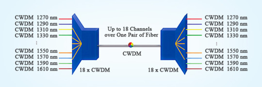
CWDM was standardized by the ITU-T G.694.2 based on a grid or wavelength separation of 20 nm in the range of 1270-1610 nm. It can carry up to 18 CWDM wavelengths over one pair of fibers. Each signal is assigned to a different wavelength of light. Each wavelength does not affect another wavelength, so the signals do not interfere. Each channel is usually transparent to the speed and data, so the voice, video, and other services can be transported simultaneously over a single fiber or fiber pair.
CWDM Network Component
A multiplexer (Mux) combines multiple wavelength channels on a single fiber, and a demultiplexer (Demux) separates them again at the other end. A Mux/Demux set-up is used to increase the end-to-end capacity of a deployed fiber. The Mux is located in the central office, and the Demux is located in the cabinet or splice closure from which the fibers go to their destination in a star-shaped topology.

Features and Benefits
CWDM provides low insertion loss, low polarization-dependent loss, low cost, low-temperature sensitivity, low power consumption, high channel isolation, high data rate, high stability, high reliability, small size, and ease of installation and deployment.
Applications
CWDM is used in metropolitan area networks (MAN), local area networks (LAN), storage area networks (SAN),10-gigabit ethernet, passive optical networks (PON), WDM transmission systems, FTTx networks, 5G front-haul, data centers, online monitoring, fiber optic amplifier, etc.

Conclusion
CWDM has become the preferred solution for increasing the bandwidth of metro/regional and optical access networks. And it has proven to be sufficiently robust, low-cost, and reliable for upgrading the optical network to accommodate future growth. Sun Telecom specializes in providing one-stop total fiber optic solutions for all fiber optic application industries worldwide. Contact us if any needs.
1 note
·
View note
Text
Uses for an optical isolator

Rotators Difference between an Optical Circulator & Isolator & RotatorĪn optical circulator is used to route the incoming light signals from port 1 to port 2 in a way that if some of the emitted light is reflected back to the circulator, it doesn’t exit from port 1 but from port 3. This rotator is used for amplitude modulation of light and is an integral part of optical isolators and optical circulators. What is an optical rotator?Īn optical rotator is typically an in-line Faraday rotator that is designed to rotate the polarization of the input light by 45 degrees. This is what makes it possible to achieve higher isolation. Hence, it adds to the total of 90 degrees when light travels in the forward direction and then the same in the backward direction. It happens because of the change in the relative magnetic field direction, positive one way, and negative the other way. It means that the rotation is positive 45 degrees in the forward direction and negative 45 degrees in the reverse direction. The polarization rotation caused by the Faraday rotator always remains in the same relative direction. Its main component is the Faraday rotator which ensures non-reciprocal rotation while maintaining linear polarization. What is an optical isolator?Īlso known as an optical diode, an optical isolator is an optical passive component that allows the light to travel in only one direction. While some circulators are three-port devices, there are also four-port circulators. In short, it is designed such that the light coming from one port exits from the next port. What is an optical circulator?Īn optical circulator is a high-performance light-wave component that is designed to route the incoming light signals from Port 1 to Port 2 and the incoming light signals from Port 2 to Port 3. Circulator & Isolator & RotatorĪs we are discussing specifically optical passive components, you will learn here about optical circulators, optical isolators, and optical rotators rather than their electronic counterparts. So, if you are curious to know about these little yet important optical passive components, read the blog till the end. We will first talk about what these components exactly are and then share what makes them different from each other. Today, we will discuss three different optical passive components, namely circulator & isolator & rotator. What is a polarization maintaining filter coupler?.A Concise Selection Guide for In-Line Polarizers.What is the importance of 80um PM fiber components?.The Growing Demand for PM Fiber Components in 2023 and Beyond.Why Should Polarization Maintaining Filter Coupler Feature High Extinction Ratio?.Polarizing Beam combiners/splitters (2).High Power Faraday Rotator and Isolator (1).(6+1)X1 Pump and Signal Combiner 2+1X1 Pump Combiner 8CH CWDM Module 16CH CWDM Module 19" rack mount chassis CWDM 1060nm Cladding Power Stripper 1064nm Band-pass Filter 1064nm Components 1064nm Fiber Collimator 1064nm High Power Isolator ABS plastic box Cladding Power Stripper Collimator Compact CWDM Module CWDM CWDM Multiplexer CWDM Mux/Demux CWDM MUX/DEMUX Module DWDM DWDM Multiplexer fiber optica connector fiber optic coupler FTTX Fused Coupler fused wdm FWDM High Power Fused Coupler High power isolator Isolator LGX CWDM Module Mini Size CWDM Mini Size Fused WDM Multimode High Power Isolator OADM optical circulator optical coupler Optical fiber communication optical isolator PLC Splitter pm circulator PM Components pm isolator pump combiner Pump Laser Protector WDM DK Categories
0 notes
Text
Huawei Certification H19-315-ENU Real Questions
To help you pass your H19-315-ENU HCSA-Presales-Transmission & Access exam, you can study PassQuestion HCSA-Presales-Transmission & Access H19-315-ENU Real Questions with less effort. You would have a basic and advanced understanding of all the concepts of HCSA-Presales-Transmission & Access certification. These H19-315-ENU questions and answers are ready by the Huawei experts so it will allow you to prepare and pass the exam with brilliant results. With the help of PassQuestion HCSA-Presales-Transmission & Access H19-315-ENU Real Questions, you would be able to pass this exam in the first attempt with maximum grades.
HCSA-Presales-Transmission & Access Certification (H19-315)
With HCSA-Presales-Transmission & Access certification (Exam Code: H19-315) , you will obtain basic principle of WDM/Access and an in-depth understanding of Huawei DCI & Campus Optix product and Solutions, will be able to provide customization, and possess pre-sales design capabilities on marketing DCI & Campus Optix products and solutions.This HCSA-Presales-Transmission & Access certification is for sales professionals of partners who sell the Huawei DCI& Campus Optix product, and those who want to obtain the HCSA-Presales-Transmission & Access certification.
Exam Details
Exam Code: H19-315 Exam Type: Written examination Exam Format: Single-answer Question, Multiple-answer Question, True or false Time: 90 min Passing Score/Total Score: 600/1000 Exam Cost: 100USD Language: English,Japanese
HCSA-Presales-Transmission & Access Exam Knowledge Points
1.WDM OTN principle 5% 2.OptiXtrans DC908 Solutions and Technologies Introduction 20% 3.OptiXtrans DC908 Specification & Hardware Introduction 15% 4.OptiXtrans DC908 Network Design & Configuration & Quotation 10% 5.PON Principle Introduction 5% 6.Huawei Campus OptiX Solution Introduction 20% 7.Huawei Campus OptiX Solution Hot-sale Product 15% 8.Huawei Campus OptiX Solution Network Design and Quotation 10%
View Online HCSA-Presales-Transmission & Access H19-315-ENU Free Questions
In the WDM model, which functional unit completes the O-E-O conversion? A. OLA B. MUX C. DEMUX D. OTU Answer: D
Where are the main application scenarios of DC908? A. Metro complex network B. Backbone C. DC point-to-point interconnection Answer: C
What is the smallest device currently provided by Huawei's transmission products? A. OptiXstar A810 B. OptiXtrans E6604 C. OptiXtrans E6608 D. OptiXtrans E9605 Answer: A
What are the highlights of the enhanced MSTP? (Multiple choice) A. Smart Hard Pipe B. Large bandwidth, high integration, flexible configuration C. Physical isolation, high security D. Operation and maintenance are consistent with traditional SDH Answer: ABCD
What are the components of 100G key technologies? (Multiple choice) A. WDM side interface technology B. OTN Processing Technology C. Client-Side Interface Technology D. Dispersion compensation technology Answer: ABC
What are the advantages of Huawei's financial data center transmission solution? (Multiple choice) A. Low latency B. Large bandwidth C. Multi-service interface and compatibility D. High reliability and easy operation and maintenance Answer: ABCD
What are the software and hardware protections supported by Huawei's distribution network PON solution? (Multiple choice) A. Hand in hand protection B. 6kV lightning protection for power and communication ports C. AES encryption D. Two-fiber bidirectional multiplex section protection Answer: ABC
The advantages of PON access are low cost and high reliability A. True B. False Answer: A
0 notes
Video
youtube
2CH CWDM Mux Module #cwdm #dwdm #wdm
#youtube#The 2-Channel CWDM MUX Module efficiently merges two data channels into one fiber for cost-effective network expansion.
0 notes
Text
arkoptics.com
A passive multiplexer in most networks consists of a mux and demux optical component. The mux combines, or multiplexes, wavelengths onto a fiber. The demux on the other end of the connection splits, or de-multiplexes, the connections.
In DWDM system, DWDM mux demux is two indispensable modules. Mux (Multiplexer) is a module at the transmitter end that brings several data signals together for transporting over a single fiber, while Demux (Demultiplexer) is a module at the receiver end that separates the signals that come together and passes each channel to an optical receiver.
CWDM mux demux (Coarse Wavelength Division Multiplexer/Demultiplexer) is a flexible, low-cost solution that enables the expansion of existing fiber capacity. CWDM multiplexer is for combining signals together, while demultiplexer is for splitting signals apart.
A polarization-maintaining (PM) WDM filter is a small device used to multiplex PM signals while maintaining the output polarization. When you are using highly efficient systems, PM fibers and PM signals play a very critical role in ensuring the desired efficiency.
Fiber Patch Cord & Cable Assembly, often called fiber patch cable, fiber jumper, or fiber patch lead, is a length of fiber cable that terminated with fiber optic connectors (LC, SC, MTRJ, ST and etc.) at each end. The connectors allow fiber optic patch cord to be rapidly connected to an optical switch or other telecommunications/computer device.
Fiber loopback is widely used for various applications. In terms of telecommunication, loopback is a hardware or software method to feed a received signal or data back to the sender. It is very useful for solving physical connection problems.
Fiber terminators(Plug-in type or Build-out type) are used to terminate unused fiber connector ports in fiber optic systems so optical terminators unwanted reflections are not introduced back into the system. It is used in the fiber-optic networks to install on possibly unused ports.
Fiber optic isolator is a passive component used for fiber optic communications. As a magneto-optic device, the purpose of optical isolator is to allow light to be transmitted in only one direction. An optical isolator is a device that is designed to allow the optical signal travel in the forward direction while block reflections that would travel in the backward direction. Optical isolators are critically important in many applications in optical systems.
FBT splitter(fused biconical taper) is the traditional technology in which two fibers are placed closely together, typically twisted around each other and fused together by applying heat while the assembly is being elongated and tapered. A signal source controls the desired coupling ratio. The fused fibers are protected by a glass substrate and then protected by a stainless steel tube, typically 3 mm diameter by 54 mm long. FBT splitters are widely accepted and used in passive optical networks.
The PLC splitters are used to separate or combine optical signals. A PLC (planar lightwave circuit) is a micro-optical component based on planar lightwave circuit technology and provides a low-cost light distribution solution with small form factor and high reliability. PLCs are manufactured using silica glass waveguide circuits that are aligned with a v-groove fiber array chip that uses ribbon fiber. Once everything is aligned and bonded, it is then packaged inside a miniature housing. PLC splitters have high quality performance, such as low insertion loss, low PDL, high return loss, etc.
1 note
·
View note
Text
Einführung von 18-Kanal-CWDM-Mux/Demux für 10G-Netzwerke
Einführung von 18-Kanal-CWDM-Mux/Demux für 10G-Netzwerke
Stellen Sie sich vor, Sie verwandeln ein Häuschen in einen majestätischen Wolkenkratzer ohne jegliche Innovation oder Konstruktion. Dies ermöglicht Wavelength-Division Multiplexing (WDM) mit Ihrem bestehenden Glasfasernetz. Ohne den Einsatz zusätzlicher Glasfasern multiplext der WDM-Netzwerk-Mux mehrere optische Signale auf einer einzigen Glasfaser, indem verschiedene Wellenlängen verwendet…
View On WordPress
0 notes
Text
Silicon Photonics Market Research Report, Size, Share, Industry Outlook 2024
Overview
The Global Silicon Photonics Market is expected to reach USD 2,518.59 Million by 2024 at a CAGR of 22.93% during the forecast period. Market Research Future (MRFR), in its report, envelops segmentations and drivers to provide a better glimpse of the market in the coming years.
Silicon photonics uses various components in conjunction to increase the processing speed and power of computers. The data is transferred using light pulses (laser) and is multiplex at the transmitter end using a multiplexer. The data traverses through a fiber optic channel and is demultiplexed at the receiver end. A photodetector then converts the light pulses into data. Silicon photonics has observed major applications in optical communication, optical routers, and signal processors, long-range telecommunications, and light-field displays. Silicon photonics is thus widely used in data centers and 5G communications. However, it has started developing its usage in commercial security, consumer electronics, and military sectors.
Competitive Analysis
The Key Players of the Global Silicon Photonics Market are Infinera Corporation (US), Cisco Systems Inc. (US), Intel Corporation (US), IBM Corporation(US), Mellanox Technologies Ltd (Israel), Hamamatsu Photonics KK (Japan), STMicroelectronics NV (Switzerland), Finisar Corporation (US), FLIR Systems (US), IPG Photonics Corporation (US), NKT Photonics (Denmark), SICOYA (Germany), AIO Core Co. Ltd (Japan) and DAS Photonics (Spain).
In June 2019, NKT photonics partnered with Oxide Corporation to develop and manufacture deep ultraviolet and violet ultrafast lasers. This partnership is focused on growing micromachining in the semiconductor and healthcare industries.
In November 2018, IPG Photonics launched a new generation of high-power fiber lasers for industrial applications. These new generation lasers consist of three innovations: adjustable mode beam capability, integrated weld monitoring technology, and QCW 2x Peak Power mode on CW lasers.
Get Free Sample Report @ https://www.marketresearchfuture.com/sample_request/2809
Segmental Analysis
The Global Silicon Photonics Market has been segmented based on Product, Component, End User, and Region.
Based on the product, the market has been classified as transceivers, active optical cable, optical multiplexers, variable optical attenuators, optical engines, and others. The transceivers segment accounted for the largest market share in 2018, while the optical multiplexers segment is expected to register the highest CAGR during the forecast period. A transceiver is a combination of transmitter and receiver included in the same package. The transmitter portion of the silicon photonics takes many high-speed electrical channels and converts them into a suitable high-speed optical signal. An active optical cable converts the electrical signal into the optical signal over short and long distances. AOC’s are mainly deployed in data centers and high-performance computing applications where the combination of value and distance is required. Optical multiplexers consist of combiners, filters, tap couplers, splitters, and optical fibers. There are mainly three different techniques in multiplexing light signals onto a single optical fiber link, namely code division multiplexing (CDM), wavelength division multiplexing (WDM), and optical time-division multiplexing (OTDM). A variable optical attenuator is a type of passive component that reduces the amplitude of the light signal without changing the waveform. An optical engine is a setup that contains electronics and controls. Optical engines do not include heat removal interface and pumping sources of a fiber laser.
Based on component, the market has been classified as laser, photodetector, modulator, micro-optics (microlens, micromirror, light diffuser, beam shapers, and others) and passive optic components (silicon lens, optical receptacles, AWG terminals, optical isolators, mux/demux modules, micro-optical filters). The laser segment accounted for the largest market share in 2018, photodetector segment is expected to register the highest CAGR during the forecast period. In optical fiber communication, a laser (source of light) is used to emit electromagnetic radiation in order to detect faults, microbeads and breaks, and characterizing link-loss. Lasers add a mechanism for optical feedback such as mirrors, to stimulate further emission and create a high-intensity beam of radiation. A photodetector is a device that absorbs the light and converts the optical energy into measurable electric current. The two main types of photodetectors are thermal and photon. An optical modulator is a device that is used for deploying a property of light. Acousto-optic modulators, electro-optic modulators, electroabsorption modulators, interferometric modulators, fiber-optic modulators, liquid crystal modulators, and micromechanical modulators are a few types of optical modulators. Microlens is also referred to as a micro lenticular array which is used to increase the optical fill factor in charged coupled devices (CCD) such as interline-transfer devices that suffer from reduced aperture due to metal shielding. Micromirrors are microscopic size mirrors that are structured in matrix combinations to form a digital micromirror device (DMD). Diffusers are optical components used to allocate light from a source while removing bright spots equally. Beam shaper is a type of optical device that reshapes a light beam. Silicon lenses are mainly used for infrared LED applications; they also prove beneficial in the silicon photonics transceiver. Receptacles are used to connect optical connectors with optical modules and align the optical module axis. American Wire Gauge (AWG) is the US standard set for non-ferrous wire conductor sizes. Optical isolators are devices used for transmission of the optical signal. It supports unidirectional mode of transmission hence it is useful in conjunction with lasers and majorly used to avoid unwanted optical reflections in optical systems. Mux/Demux module is a passive device, available in a variety of wavelength combinations generally from 1270nm to 1610nm. An optical filter is a key component in optical networks. Optical fibers are essential to split and combine wavelength channels.
Based on end-user, the market has been classified as consumer electronics, IT & telecommunication, commercial, military & defense, healthcare, and others. The IT & telecommunication segment accounted for the largest market share in 201; it is expected to register the highest CAGR during the forecast period. Silicon photonics primarily enables high-speed data transfer. Data transfer is applicable for various devices such as smartphones, wearable devices, and tablets and laptops. Silicon photonics is used to create transmitters and receivers for fiber-optic telecommunications. Many companies are switching to silicon photonics from traditional copper cables. With the help of silicon photonics, companies can develop compact, more efficient, and more affordable products in which optical signals are used for precise measuring, laser imaging, and rapid data transfer. The military uses imaging and other information for activity-based intelligence by lightweight, low-power, and low-cost silicon photonics. Silicon photonics is used in DNA sequencing machines, miniaturized diagnostic tests using disposable photonic chips, accurate body monitoring sensors, brain stimulation machines.
Table of Content:
5 MARKET FACTOR ANALYSIS
5.1 VALUE CHAIN ANALYSIS
5.2 OPTICAL COMPONENT PROVIDERS
5.2.1 LIST OF COMPONENT PROVIDERS
5.2.2 COMPETITIVE LANDSCAPE
5.3 ELECTRONIC COMPONENT PROVIDERS
5.3.1.1 LIST OF COMPONENT PROVIDERS
5.3.2 COMPETITIVE LANDSCAPE
5.4 COMPONENT PROVIDERS: PORTERS FIVE FORCES
5.4.1 THREAT OF NEW ENTRANTS
5.4.2 BARGAINING POWER OF SUPPLIERS
5.4.3 THREAT OF SUBSTITUTE
5.4.4 BARGAINING POWER OF BUYERS
5.4.5 RIVALRY
5.5 SOLUTION PROVIDERS: PORTERS FIVE FORCES
5.5.1 THREAT OF NEW ENTRANTS
5.5.2 BARGAINING POWER OF SUPPLIERS
5.5.3 THREAT OF SUBSTITUTE
5.5.4 BARGAINING POWER OF BUYERS
5.5.5 RIVALRY
6 GLOBAL SILICON PHOTONICS MARKET, BY PRODUCT
6.1 OVERVIEW
6.1.1 TRANSCEIVERS
6.1.2 ACTIVE OPTICAL CABLE (AOC)
6.1.3 OPTICAL MULTIPLEXERS
6.1.4 VARIABLE OPTICAL ATTENUATORS
6.1.5 OPTICAL ENGINES
7 GLOBAL SILICON PHOTONICS MARKET, BY COMPONENT
7.1 OVERVIEW
7.1.1 LASER
7.1.2 PHOTODETECTORS
7.1.3 MODULATORS
7.1.4 MICRO OPTICS
7.1.4.1 MICROLENS
7.1.4.2 MICROMIRROR
7.1.4.3 LIGHT DIFFUSER
7.1.4.4 BEAM SHAPERS
7.1.5 PASSIVE OPTIC COMPONENTS
7.1.5.1 SILICON LENS
7.1.5.2 OPTICAL RECEPTACLES
7.1.5.3 AWG TERMINALS
7.1.5.4 OPTICAL ISOLATORS
7.1.5.5 MUX/DEMUX MODULES
7.1.5.6 MICRO OPTICAL FILTERS
8 GLOBAL SILICON PHOTONICS MARKET, BY END USER
8.1 OVERVIEW
8.1.1 CONSUMER ELECTRONICS
8.1.2 IT & TELECOMMUNICATION
8.1.3 COMMERCIAL
8.1.4 MILITARY & DEFENSE
8.1.5 HEALTHCARE
9 GLOBAL SILICON PHOTONICS MARKET, BY REGION
9.1 OVERVIEW
9.2 NORTH AMERICA
9.2.1 MARKET ESTIMATE & FORECAST, BY COUNTRY
9.2.2 MARKET ESTIMATE & FORECAST, BY COMPONENT
9.2.3 MARKET ESTIMATE & FORECAST, BY PRODUCT
9.2.4 MARKET ESTIMATE & FORECAST, BY END USER
9.2.5 US
9.2.5.1 MARKET ESTIMATE & FORECAST, BY COMPONENT
9.2.5.2 MARKET ESTIMATE & FORECAST, BY PRODUCT
9.2.5.3 MARKET ESTIMATE & FORECAST, BY END USER
9.2.6 CANADA
9.2.6.1 MARKET ESTIMATE & FORECAST, BY COMPONENT
9.2.6.2 MARKET ESTIMATE & FORECAST, BY PRODUCT
9.2.6.3 MARKET ESTIMATE & FORECAST, BY END USER
9.2.7 MEXICO
9.2.7.1 MARKET ESTIMATE & FORECAST, BY COMPONENT
9.2.7.2 MARKET ESTIMATE & FORECAST, BY PRODUCT
9.2.7.3 MARKET ESTIMATE & FORECAST, BY END USER
9.3 EUROPE
9.3.1 MARKET ESTIMATE & FORECAST, BY COUNTRY
9.3.2 MARKET ESTIMATE & FORECAST, BY COMPONENT
9.3.3 MARKET ESTIMATE & FORECAST, BY PRODUCT
9.3.4 MARKET ESTIMATE & FORECAST, BY END USER
9.3.5 GERMNAY
9.3.5.1 MARKET ESTIMATE & FORECAST, BY COMPONENT
9.3.5.2 MARKET ESTIMATE & FORECAST, BY PRODUCT
9.3.5.3 MARKET ESTIMATE & FORECAST, BY END USER
9.3.6 UK
9.3.6.1 MARKET ESTIMATE & FORECAST, BY COMPONENT
9.3.6.2 MARKET ESTIMATE & FORECAST, BY PRODUCT
9.3.6.3 MARKET ESTIMATE & FORECAST, BY END USER
9.3.7 FRANCE
9.3.7.1 MARKET ESTIMATE & FORECAST, BY COMPONENT
9.3.7.2 MARKET ESTIMATE & FORECAST, BY PRODUCT
9.3.7.3 MARKET ESTIMATE & FORECAST, BY END USER
9.3.8 ITALY
9.3.8.1 MARKET ESTIMATE & FORECAST, BY COMPONENT
9.3.8.2 MARKET ESTIMATE & FORECAST, BY PRODUCT
9.3.8.3 MARKET ESTIMATE & FORECAST, BY END USER
9.3.9 SPAIN
9.3.9.1 MARKET ESTIMATE & FORECAST, BY COMPONENT
9.3.9.2 MARKET ESTIMATE & FORECAST, BY PRODUCT
9.3.9.3 MARKET ESTIMATE & FORECAST, BY END USER
9.3.10 REST OF EUROPE
9.3.10.1 MARKET ESTIMATE & FORECAST, BY COMPONENT
9.3.10.2 MARKET ESTIMATE & FORECAST, BY PRODUCT
9.3.10.3 MARKET ESTIMATE & FORECAST, BY END USER
9.4 ASIA-PACIFIC
9.4.1 MARKET ESTIMATE & FORECAST, BY COUNTRY
9.4.2 MARKET ESTIMATE & FORECAST, BY COMPONENT
9.4.3 MARKET ESTIMATE & FORECAST, BY PRODUCT
9.4.4 MARKET ESTIMATE & FORECAST, BY END USER
9.4.5 CHINA
9.4.5.1 MARKET ESTIMATE & FORECAST, BY COMPONENT
9.4.5.2 MARKET ESTIMATE & FORECAST, BY PRODUCT
9.4.5.3 MARKET ESTIMATE & FORECAST, BY END USER
9.4.6 JAPAN
9.4.6.1 MARKET ESTIMATE & FORECAST, BY COMPONENT
9.4.6.2 MARKET ESTIMATE & FORECAST, BY PRODUCT
9.4.6.3 MARKET ESTIMATE & FORECAST, BY END USER
9.4.7 INDIA
9.4.7.1 MARKET ESTIMATE & FORECAST, BY COMPONENT
9.4.7.2 MARKET ESTIMATE & FORECAST, BY PRODUCT
9.4.7.3 MARKET ESTIMATE & FORECAST, BY END USER
9.4.8 SOUTH KOREA
9.4.8.1 MARKET ESTIMATE & FORECAST, BY COMPONENT
9.4.8.2 MARKET ESTIMATE & FORECAST, BY PRODUCT
9.4.8.3 MARKET ESTIMATE & FORECAST, BY END USER
9.4.9 SINGAPORE
9.4.9.1 MARKET ESTIMATE & FORECAST, BY COMPONENT
9.4.9.2 MARKET ESTIMATE & FORECAST, BY PRODUCT
9.4.9.3 MARKET ESTIMATE & FORECAST, BY END USER
9.4.10 REST OF ASIA-PACIFIC
9.4.10.1 MARKET ESTIMATE & FORECAST, BY COMPONENT
9.4.10.2 MARKET ESTIMATE & FORECAST, BY PRODUCT
9.4.10.3 MARKET ESTIMATE & FORECAST, BY END USER
9.5 MIDDLE EAST & AFRICA
9.5.1 MARKET ESTIMATE & FORECAST, BY COUNTRY
9.5.2 MARKET ESTIMATE & FORECAST, BY COMPONENT
9.5.3 MARKET ESTIMATE & FORECAST, BY PRODUCT
9.5.4 MARKET ESTIMATE & FORECAST, BY END USER
9.5.5 UAE
9.5.5.1 MARKET ESTIMATE & FORECAST, BY COMPONENT
9.5.5.2 MARKET ESTIMATE & FORECAST, BY PRODUCT
9.5.5.3 MARKET ESTIMATE & FORECAST, BY END USER
9.5.6 SAUDI ARABIA
9.5.6.1 MARKET ESTIMATE & FORECAST, BY COMPONENT
9.5.6.2 MARKET ESTIMATE & FORECAST, BY PRODUCT
9.5.6.3 MARKET ESTIMATE & FORECAST, BY END USER
9.5.7 REST OF MIDDLE EAST & AFRICA
9.5.7.1 MARKET ESTIMATE & FORECAST, BY COMPONENT
9.5.7.2 MARKET ESTIMATE & FORECAST, BY PRODUCT
9.5.7.3 MARKET ESTIMATE & FORECAST, BY END USER
9.6 SOUTH AMERICA
9.6.1 MARKET ESTIMATE & FORECAST, BY COUNTRY
9.6.2 MARKET ESTIMATE & FORECAST, BY COMPONENT
9.6.3 MARKET ESTIMATE & FORECAST, BY PRODUCT
9.6.4 MARKET ESTIMATE & FORECAST, BY END USER
9.6.5 BRAZIL
9.6.5.1 MARKET ESTIMATE & FORECAST, BY COMPONENT
9.6.5.2 MARKET ESTIMATE & FORECAST, BY PRODUCT
9.6.5.3 MARKET ESTIMATE & FORECAST, BY END USER
9.6.6 ARGENTINA
9.6.6.1 MARKET ESTIMATE & FORECAST, BY COMPONENT
9.6.6.2 MARKET ESTIMATE & FORECAST, BY PRODUCT
9.6.6.3 MARKET ESTIMATE & FORECAST, BY END USER
9.6.7 REST OF SOUTH AMERICA
9.6.7.1 MARKET ESTIMATE & FORECAST, BY COMPONENT
9.6.7.2 MARKET ESTIMATE & FORECAST, BY PRODUCT
9.6.7.3 MARKET ESTIMATE & FORECAST, BY END USER
10 COMPETITIVE LANDSCAPE
10.1 OVERVIEW
10.2 MARKET SHARE ANALYSIS
10.3 COMPETITIVE BENCHMARKING
10.4 DASHBOARD: THE LEADING PLAYER IN TERMS OF NUMBER OF DEVELOPMENTS IN SILICON PHOTONICS MARKET
11 COMPANY PROFILES
11.1 STMICROELECTRONICS N.V.
11.1.1 COMPANY OVERVIEW
11.1.2 FINANCIAL OVERVIEW
11.1.3 PRODUCTS OFFERINGS
11.1.4 KEY DEVELOPMENTS
11.1.5 SWOT ANALYSIS
11.1.6 KEY STRATEGIES
11.2 IBM CORPORATION
11.2.1 COMPANY OVERVIEW
11.2.2 FINANCIAL OVERVIEW
11.2.3 PRODUCTS OFFERINGS
11.2.4 KEY DEVELOPMENTS
11.2.5 SWOT ANALYSIS
11.2.6 KEY STRATEGIES
11.3 CISCO SYSTEMS INC.
11.3.1 COMPANY OVERVIEW
11.3.2 FINANCIAL OVERVIEW
11.3.3 PRODUCTS OFFERINGS
11.3.4 KEY DEVELOPMENTS
11.3.5 SWOT ANALYSIS
11.3.6 KEY STRATEGIES
11.4 INTEL CORPORATION
11.4.1 COMPANY OVERVIEW
11.4.2 FINANCIAL OVERVIEW
11.4.3 PRODUCTS OFFERINGS
11.4.4 KEY DEVELOPMENTS
11.4.5 SWOT ANALYSIS
11.4.6 KEY STRATEGIES
11.5 AIO CORE CO. LTD.
11.5.1 COMPANY OVERVIEW
11.5.2 FINANCIAL OVERVIEW
11.5.3 PRODUCTS OFFERINGS
11.5.4 KEY DEVELOPMENTS
11.6 SICOYA
11.6.1 COMPANY OVERVIEW
11.6.2 FINANCIAL OVERVIEW
11.6.3 PRODUCTS OFFERINGS
11.6.4 KEY DEVELOPMENTS
11.7 NKT PHOTONICS A/S
11.7.1 COMPANY OVERVIEW
11.7.2 FINANCIAL OVERVIEW
11.7.3 PRODUCTS OFFERINGS
11.7.4 KEY DEVELOPMENTS
11.7.5 SWOT ANALYSIS
11.7.6 KEY STRATEGIES
11.8 IPG PHOTONICS CORPORATION
11.8.1 COMPANY OVERVIEW
11.8.2 FINANCIAL OVERVIEW
11.8.3 PRODUCTS OFFERINGS
11.8.4 KEY DEVELOPMENTS
11.8.5 SWOT ANALYSIS
11.9 FLIR SYSTEMS
11.9.1 COMPANY OVERVIEW
11.9.2 FINANCIAL OVERVIEW
11.9.3 PRODUCTS OFFERINGS
11.9.4 KEY DEVELOPMENTS
11.9.5 SWOT ANALYSIS
11.9.6 KEY STRATEGIES
11.10 DAS PHOTONICS
11.10.1 COMPANY OVERVIEW
11.10.2 FINANCIAL OVERVIEW
11.10.3 PRODUCTS OFFERINGS
11.10.4 KEY DEVELOPMENTS
11.10.5 SWOT ANALYSIS
11.11 FINISAR CORPORATION
11.11.1 COMPANY OVERVIEW
11.11.2 FINANCIAL OVERVIEW
11.11.3 PRODUCTS OFFERINGS
11.11.4 KEY DEVELOPMENTS
11.11.5 SWOT ANALYSIS
11.11.6 KEY STRATEGIES
11.12 INFINERA CORPORATION
11.12.1 COMPANY OVERVIEW
11.12.2 FINANCIAL OVERVIEW
11.12.3 PRODUCTS OFFERINGS
11.12.4 KEY DEVELOPMENTS
11.12.5 SWOT ANALYSIS
11.13 MELLANOX TECHNOLOGIES LTD
11.13.1 COMPANY OVERVIEW
11.13.2 FINANCIAL OVERVIEW
11.13.3 PRODUCTS OFFERINGS
11.13.4 KEY DEVELOPMENTS
11.13.5 SWOT ANALYSIS
11.13.6 KEY STRATEGIES
11.14 HAMAMATSU PHOTONICS KK
11.14.1 COMPANY OVERVIEW
11.14.2 FINANCIAL OVERVIEW
11.14.3 PRODUCTS OFFERINGS
11.14.4 KEY DEVELOPMENTS
11.14.5 SWOT ANALYSIS
11.14.6 KEY STRATEGIES
12 LIST OF TABLES
TABLE 1 LIST OF ASSUMPTIONS
TABLE 2 LIST OF COMPONENT PROVIDERS
TABLE 3 LIST OF COMPONENT PROVIDERS
TABLE 4 GLOBAL SILICON PHOTONICS MARKET, BY PRODUCT, 2020-2027 (USD MILLION)
TABLE 5 GLOBAL SILICON PHOTONICS MARKET, BY PRODUCT, AVERAGE SELLING PRICE (ASP), 2020-2027 (USD)
TABLE 6 GLOBAL SILICON PHOTONICS MARKET, BY COMPONENT, 2020-2027 (USD MILLION)
TABLE 7 GLOBAL SILICON PHOTONICS MARKET, BY MICRO OPTICS, 2020-2027 (USD MILLION)
TABLE 8 GLOBAL SILICON PHOTONICS MARKET, BY PASSIVE OPTIC COMPONENT, 2020-2027 (USD MILLION)
TABLE 9 GLOBAL SILICON PHOTONICS MARKET, BY SILICON LENS, 2020-2027 (USD MILLION)
TABLE 10 GLOBAL SILICON PHOTONICS MARKET, BY END USER, 2020-2027 (USD MILLION)
TABLE 11 GLOBAL SILICON PHOTONICS MARKET, BY REGION, 2020-2027 (USD MILLION)
TABLE 12 NORTH AMERICA: SILICON PHOTONICS MARKET, BY COUNTRY, 2020-2027 (USD MILLION)
TABLE 13 NORTH AMERICA: SILICON PHOTONICS MARKET, BY COMPONENT, 2020-2027 (USD MILLION)
TABLE 14 NORTH AMERICA: SILICON PHOTONICS MARKET, BY MICRO OPTICS, 2020-2027 (USD MILLION)
TABLE 15 NORTH AMERICA: SILICON PHOTONICS MARKET, BY PASSIVE OPTIC COMPONENT, 2020-2027 (USD MILLION)
TABLE 16 NORTH AMERICA: SILICON PHOTONICS MARKET, BY SILICON LENS, 2020-2027 (USD MILLION)
TABLE 17 NORTH AMERICA: SILICON PHOTONICS MARKET, BY PRODUCT, 2020-2027 (USD MILLION)
TABLE 18 NORTH AMERICA: SILICON PHOTONICS MARKET, BY END USER, 2020-2027 (USD MILLION)
TABLE 19 US: SILICON PHOTONICS MARKET, BY COMPONENT, 2020-2027 (USD MILLION)
TABLE 20 US: SILICON PHOTONICS MARKET, BY MICRO OPTICS, 2020-2027 (USD MILLION)
TABLE 21 US: SILICON PHOTONICS MARKET, BY PASSIVE OPTIC COMPONENT, 2020-2027 (USD MILLION)
TABLE 22 US: SILICON PHOTONICS MARKET, BY SILICON LENS, 2020-2027 (USD MILLION)
TABLE 23 US: SILICON PHOTONICS MARKET, BY PRODUCT, 2020-2027 (USD MILLION)
TABLE 24 US: SILICON PHOTONICS MARKET, BY END USER, 2020-2027 (USD MILLION)
TABLE 25 CANADA: SILICON PHOTONICS MARKET, BY COMPONENT, 2020-2027 (USD MILLION)
TABLE 26 CANADA: SILICON PHOTONICS MARKET, BY MICRO OPTICS, 2020-2027 (USD MILLION)
TABLE 27 CANADA: SILICON PHOTONICS MARKET, BY PASSIVE OPTIC COMPONENT, 2020-2027 (USD MILLION)
TABLE 28 CANADA: SILICON PHOTONICS MARKET, BY SILICON LENS, 2020-2027 (USD MILLION)
TABLE 29 CANADA: SILICON PHOTONICS MARKET, BY PRODUCT, 2020-2027 (USD MILLION)
TABLE 30 CANADA: SILICON PHOTONICS MARKET, BY END USER, 2020-2027 (USD MILLION)
TABLE 31 MEXICO: SILICON PHOTONICS MARKET, BY COMPONENT, 2020-2027 (USD MILLION)
TABLE 32 MEXICO: SILICON PHOTONICS MARKET, BY MICRO OPTICS, 2020-2027 (USD MILLION)
TABLE 33 MEXICO: SILICON PHOTONICS MARKET, BY PASSIVE OPTIC COMPONENT, 2020-2027 (USD MILLION)
TABLE 34 MEXICO: SILICON PHOTONICS MARKET, BY SILICON LENS, 2020-2027 (USD MILLION)
TABLE 35 MEXICO: SILICON PHOTONICS MARKET, BY PRODUCT, 2020-2027 (USD MILLION)
TABLE 36 MEXICO: SILICON PHOTONICS MARKET, BY END USER, 2020-2027 (USD MILLION)
TABLE 37 EUROPE: SILICON PHOTONICS MARKET, BY COUNTRY, 2020-2027 (USD MILLION)
TABLE 38 EUROPE: SILICON PHOTONICS MARKET, BY COMPONENT, 2020-2027 (USD MILLION)
TABLE 39 EUROPE: SILICON PHOTONICS MARKET, BY MICRO OPTICS, 2020-2027 (USD MILLION)
TABLE 40 EUROPE: SILICON PHOTONICS MARKET, BY PASSIVE OPTIC COMPONENT, 2020-2027 (USD MILLION)
Get Complete Report @ https://www.marketresearchfuture.com/reports/silicon-photonics-market-2809
About Us
Market Research Future (MRFR) is an esteemed company with a reputation of serving clients across domains of information technology (IT), healthcare, and chemicals. Our analysts undertake painstaking primary and secondary research to provide a seamless report with a 360 degree perspective. Data is compared against reputed organizations, trustworthy databases, and international surveys for producing impeccable reports backed with graphical and statistical information.
We at MRFR provide syndicated and customized reports to clients as per their liking. Our consulting services are aimed at eliminating business risks and driving the bottomline margins of our clients. The hands-on experience of analysts and capability of performing astute research through interviews, surveys, and polls are a statement of our prowess. We constantly monitor the market for any fluctuations and update our reports on a regular basis.
Media Contact:
Market Research Future (Part of Wantstats Research and Media Private Limited)
99 Hudson Street, 5Th Floor
New York, NY 10013
United States of America
+1 628 258 0071 (US)
+44 2035 002 764 (UK)
Email: [email protected]
Website: https://www.marketresearchfuture.com
0 notes
Text
Introduction to 40GBASE QSFP+ Optical Modules
40GBASE Optical modules are different from optical handsets with a 40Gbps transmission rate, in which the QSFP is the primary structure factor. Also, the 40G QSFP+ Modules are the most extensively applied optical handsets. In this article, 10Gtek will present distinctive organization arrangements of the most overall 40G QSFP+ handsets to assist you with having a simpler understanding and better determination of the modules.
Highlights and Benefits of 40G QSFP+ Transceiver
Hot-pluggable to 40G Ethernet QSFP+ port
QSFP+ MSA consistent and interoperable with other IEEE-agreeable 40G interfaces
RoHS affirmed and checked unrivaled execution, solidness, and dependability
Rapid electrical interface dependent on IEEE 802.3ba agreeable
4 Parallel paths plan of SR4, ESR4, PSM LR4, and PSM IR4
4 CWDM paths MUX plan of LR4, IR4, and ER4
Low force utilization under 3.5W
40G QSFP+ SR4 and 40G QSFP+ ESR4 Transceivers
The signs' conveyance of 40G QSFP+ SR4 handset is sent through four autonomous full-duplex channels. MPO/MTP Connector is a basis applied to the Transceiver in 40G information transmission, and MMF(Multi-Mode Fiber) is needed to work over inside the handset. At the point when it's running over the OM3 optical fiber jumper the transmission separation is 100m, while the scope can be 150m when it's running over the OM4 optical fiber jumper.

40G QSFP+ ESR4 is a similar working rule as 40G QSFP+ SR4 however with an advanced separation of transmission up to 300m over OM4 optical fiber jumper. It tends to be considered as an updated form of 40G QSFP+ SR4 handset.
40G QSFP+ BIDI Transceiver
The QSFP+ BIDI handset is created to address the difficulties of fiber foundation by giving the capacity to send full-duplex 40G traffic more than one duplex MMF link with LC connectors(Figure 2). At the end of the day, this handset upholds 40G association more than one sets of MMF links while permitting 40G to be sent utilizing a similar foundation as 10G (10GBASE-SR) without the need to include any strands.
Examination of 40G QSFP+ BIDI and 40G QSFP+ SR4
40GBASE-SR BIDI handset eliminates 40G cabling cost hindrances in server farm organizations. It gives colossal investment funds and effortlessness contrasted with other 40G QSFP+(MMF) transceiver(QSFP+ SR4). Additionally, it permits associations to move the current 10G cabling framework to 40G at no expense and to grow the foundation with low capital speculation.

40G QSFP+ PSM IR4 and 40G QSFP+ PSM LR4 Transceivers
QSFP+ PSM IR4/LR4 is an exceptionally coordinated four-channel optical handset with the benefits of the high thickness of port and lower cost. The optical port embraces a PSM(Parallel Single Mode) innovation and a four-way equal plan MPO/MTP interface which empowers the transmission separation up to 1.4km of IR4 and 10km of LR4. It has been planned with structure factor, optical/electrical association, and computerized analytic interface consistent with MSA(Multi-Source Agreement), these highlights are very attainable to meet the harshest outer working conditions including temperature, moistness, and EMI interface.
The handset can run through the I2C two-wire sequential interface which is accessible to send and get more intricate control signals and to get computerized symptomatic data. By correlation with 40G QSFP+ SR4, they are both similarly of working yet QSFP+ PSM IR4/LR4 is working over SMF(Single Mode Fiber) that is the equal optical signs are conveyed through eight single-mode strands.
40G QSFP+ CWDM LX4/LR4 Lite/LR4/ER4 Transceiver
Recognized from DWDM for example Thick Wavelength Division Multiplex, CWDM known as Coarse Wavelength Division Multiplex is an inventive innovation for moving a lot of information between locales. It builds transfer speed by permitting distinctive information streams to be sent all the while over a solitary optical fiber organization. Thusly, WDM amplifies the use of fiber and assists with streamlining network speculations.
QSFP+ LX4 is an optical module planned particularly for working over both SMF and MMF with transmission separation of up to 150m on OM4 MMF and 2km on SMF. The focal frequencies of the 4 CWDM channels are 1271nm, 1291nm, 1311nm, and 1331nm as individuals from the CWDM frequency framework characterized in ITU-T G.694.2. There is a duplex LC connector for the optical interface and a 148-pin connector for the electrical interface. For applications over SMF, the handset is utilized as a QSFP+ LR4 Lite module and SMF links are legitimately associated with the LC connectors of the module.

QSFP+ LR4 Lite/LR4/ER4 Module bolsters the connection length of up to 2km, 10km, and 30km individually by working over a standard pair of G.652 SMF with duplex LC connector. Inside the gadget, the 40G Ethernet signals are sent more than four frequencies which are figured out how to multiplex and demultiplex. There are 4 information channels to send flags simultaneously. At the sending side, the 4 channels of optical signs are consolidated together by multiplexer while at getting end there is a breakdown handled into 4 channels of optical signals by the demultiplexer. The module includes high thickness, minimal effort, rapid, huge limit, and low force utilization.
CWDM versus PSM, What's The Difference?
From an optical handset module structure perspective, PSM appears to be more financially savvy since it utilizes a solitary uncooled CW (ceaseless wave) laser which parts its yield power into four incorporated silicon modulators. Additionally, its exhibit fiber coupling to an MTP connector is generally less complex. Nonetheless, from a framework perspective, PSM would be more costly when the connection separation is long, basically because of the way that PSM utilizes 8 optical single-mode filaments while CWDM utilizes just 2 optical single-mode strands.
Tantamount with Third-Party QSFP+
All 10Gtek's 40G QSFP+ Transceiver is benevolently viable with outsider QSFP+ gadget, for example, Cisco, Extreme, Brocade, Juniper, HP, Dell, Arista, Huawei, and other known brands. Our 40G QSFP+ handset will give you a phenomenal answer for set up network association without costly expense.
2 notes
·
View notes
Text
WDMs
https://www.china-tscom.com/products/wdm/

T&S has a profound optical process foundation on passive WDM devices; it has unique process technology in optical coating, optical element polishing, optical coupling and optical parameter testing, and is equipped with advanced automatic optical coupling and testing platforms. Provide highly reliable WDM series of products.
TFF Type WDM
T&S TFF WDM is based on Thin Film Filter (TFF) technology. Our Filter-Based WDM product family covers following wavelength windows commonly used in optical fiber systems: 1310/1490/1550nm (for FWDM Device), 1271~1611nm (for CWDM Device or Module), 1525~1565nm (C_band for 100G/200G DWDM Device or Module) and 1269.23~1318.35nm (for 800G LWDM Device or Module), 1271±3.5~1371±3.5nm (for MWDM Device or Module) and 1270/1310/1490/1534/1577/1610/1650nm (for Cex-wdm Modules, including GPON, XG-PON, NG-PON2 and OTDR )
PLC Type WDM
Instead of taking a thin film filter to mux or demux wavelengths, PLC type achieves the same goal by using chip PLC, which uniformly divides and guides light with different wavelengths. At T&S, we currently provide multi-channel AWG DWDM Modules and 4ch CWDM/LWDM Devices.
1525~1565nm (C_band for 100G multi-channel AWG Module) and 1271~1331nm&1295.56~1309.14nm(for PLC CWDM4&LWDM4 Devices, it used for 4x10 Gbps CWDM TOSA&ROSA for QSFP+ or 4X25 Gbps LAN-WDM TOSA&ROSA for QSFP+
0 notes