#3-axis force sensor
Explore tagged Tumblr posts
Visit Tumblr Blog
Explore Tumblr blogs with no restrictions, modern design and the best experience.
Last Seen Tumblr Blogs


Fun Fact
28.6 is the average number of monthly visits per US mobile user.
Text
Forsentek Co., Limited supplys multi axis load cells for force measurement and control in industrial field. 3 axis load cell
#3 axis load cell#multi axis force sensor#multi-axis load cell#3-axis force sensor#triaxial load cell
1 note
·
View note
Text
When someone tells you that they put their ducks in a row, don't listen to them. Waterfowl, and ducks in particular, are nearly impossible to align. Even if you only have two ducks – which is hardly anything to brag about – the axis formed by placing them side by side will last about five minutes before they're running off to eat snails in your yard.
Hello, I'm Seat Safety Switch, and this is Cosmos. We found the rights to the show at a garage sale. Even though the owner tried to chase us down on foot to get them back when he realized what happened, it turns out that Medium-Sized Mike's wheezing 3-speed-auto first-gen Dodge Neon was still much faster than a middle-aged dude wearing Vibrams who didn't pay enough attention to ominous folders marked "PBS Legal" before selling them for fifty cents.
In this, our spaceship of the imagination, we will soon visit: ducks. Humanity has long lived aside these quacking nightmares, but we don't know what makes them tick. Even accomplished biologists and veterinarians have looked inside them and written what I am assured is the equivalent to a Haynes manual, but we still don't know why ducks do what they do. The only thing we do know? Motherfuckers hate being in rows.
Some think that it's because of the magnetic sensors in their bills, which also force them into sleep mode when you accidentally bump them against the phone in your pocket when you're trying to steal their bread from the pond. Others believe that the ducks are merely more understanding than most animals of their true lack of purpose in the disordered chaos of the universe. Perhaps we'll never know. The one thing we do know is that anyone who tells you that they cleaned their garage up is a total liar. I guarantee you that if you go over there right now, and open up any of their cupboards, a ton of hoarded tools and paint will fall out. Ducks. Don't trust 'em.
213 notes
·
View notes
Text
I'm extracting out (and updating) my current hypothesis about what happened with the Titan submersible from my extremely large commentary post (link to its current iteration: https://www.tumblr.com/jackalgirl/762730158416379904/only-one-1-day-behind-now-just-got-done-with?source=share -- I'm very much behind on watching and probably won't catch up until the weekend.


I've attached images, above, which I've taken from Dr. Kramer's presentation on behalf of the NTSB (link to original presentation here: https://media.defense.gov/2024/Sep/25/2003553505/-1/-1/0/CG-107%20NTSB%20TITAN%20MATERIAL%20ANALYSIS.PDF_REDACTED.PDF). Please note that the red circle and "Group 4" annotation on the slide labelled "Strain Gage Response" are from me (they're not in the original presentation).
If I'm reading this correctly (and I might not be), it looks like that at the time of the loud bang, there was a marked increase in strain at the sensor point in the axial (longitudinal, or along the forward/aft axis of the vehicle) direction, and a slightly smaller (but still marked) decrease in strain in the radial (around the right/left, or "starboard/port" as we would say in sailing, circumference of the vehicle).
The other two slides are Dr. Kramer's own visualizations: instead of plotting depth/strain over time as OceanGate had done, he simply focused on depth vs. strain. You can see the difference pre-"loud bang" (which happened on Dive 80) and post-. Instead of being a straight linear increase and decrease, now the gauge is slow to pick up the increase in strain during descent and quick to let it off on ascent.
So I suspect that in Dive 80, the "loud bang" was the sound of the hull delaminating into the three shells Dr. Kramer mentioned in his presentation (layer 1 into shell 1, layers 2/3 into shell 2, layers 4/5 into shell 3), with the most distinct and complete delamination between shell 1 and 2. at least two shells (layer 1 and layers 2-5), or possibly the three layers found in the debris (layer 1 as shell 1, layers 2/3 as shell 2, layers 3/4 as shell 3). I'm thinking that it could have been two shells at the point of the "loud bang" (layer 1 as shell 1, layers 2-5 as shell 2), and that the implosion itself caused layers 2-5 to separate into two distinct shells. But I believe that layer 1 definitely delaminated from the rest and the sound of this happening was the "loud bang".
This seems to make sense with respect to the strain gauge response: suddenly layer 1 is not being compressed by the other layers in the radial direction (less strain), and it's not being supported by the other layers in the axial direction as much, a direction in which the hull is acting like a bridge (it was only supported by the titanium rings at the end, so there would have been considerable stress in the middle since it was a straight line and not an arch, so more strain). I hypothesize that this delamination was most pronounced on the forward end of the hull.
What this tells me is that the strain gauges on layer 1, now separated from the rest of the hull's layers (at least in the forward area of the hull), would not have shown the same strain until the increased pressure (due to depth) had compressed the outer shell(s) enough to start affecting layer 1/shell 1.
I believe that the rubbing noted on shell 1 occurred because the outer two shells (possibly still laminated, so really just two shells at this point maybe) had more freedom to move and were, in fact, moving. This also weakened the epoxy bond between the shells and the forward ring.
On the final dive, the epoxy gave way. This allowed explosive saltwater intrusion into the interstices between the shells, popping them apart, Because the delamination was most pronounced in the forward part of the shell, the carbon fiber there for the most part simply shattered. Larger pieces remained intact in the aft direction. Parts of shell 3 did not delaminate at the adhesive part, but were simply cracked off by the forces being applied from the forward direction.
I'll come back and reassess this hypothesis when the hearings are over (or have reached a point where they have settled on a determination of what happened), and see how closely this allies with the conclusion they reach.
I would be curious to see if there would be any attempt to make a new hull (or at least a section, or "coupon") in the same way as Titan's hull, then put it under pressure and seeing if the layers would pop apart and if they do, what sounds it makes.
12 notes
·
View notes
Text

Ocean Heat for Hurricane Helene
When tropical weather watchers in the U.S. began tracking a disturbance brewing near the Yucatan Peninsula in mid-September, there were already worrisome signs in ocean temperature data for the Gulf of Mexico and the Caribbean Sea.
Sea surface temperature and ocean heat content data—both derived from satellite observations—showed a tongue of unusually warm water extending north from the Caribbean Sea into the Gulf of Mexico toward the Florida Panhandle. It was a sign that the Loop Current—a variable current that shunts water from the Caribbean Sea into the Gulf of Mexico, around Florida, and up the eastern coast of the U.S.—had shed an eddy of warm water that was lingering uncomfortably close to U.S. shores.
Such features can make storms more dangerous because they provide a store of energy for passing hurricanes to draw from as they approach land, explained Scott Braun, a research meteorologist at NASA’s Goddard Space Flight Center. “These warm core eddies are a fairly persistent feature in the gulf and represent a deep layer of warm water that is much less likely to be disrupted by strong surface forcing by the hurricane winds,” he said.
The map above shows sea surface temperatures on September 23, based on data from the Multiscale Ultrahigh Resolution Sea Surface Temperature (MUR SST) project, a NASA Jet Propulsion Laboratory effort that blends measurements of sea surface temperatures from multiple NASA, NOAA, and international satellites, as well as ship and buoy observations. Surface waters above 27.8 degrees Celsius (82 degrees Fahrenheit)—the temperature generally required to sustain and intensify hurricanes—are represented in red on the map. The tongue of warm water is also visible in maps of sea surface temperature anomalies on NASA’s State of the Ocean data viewer.
“A warm ocean isn’t everything when it comes to hurricanes, but it’s a lot,” noted University of Miami hurricane researcher Brian McNoldy as the storm intensified near the Yucatan Peninsula. Not only were much of the seas along the storm’s path up to a “toasty” 31°C, but the warm water ran deep, fueling the storm with what McNoldy described as “a source of high-octane fuel.”

But ocean heat is just one among several factors that together control whether a hurricane intensifies rapidly or fizzles. In Helene’s case, the presence of high vertical wind shear, a patch of dry air on one side of the storm, and that only part of the storm hit the warmest part of the eddy likely helped constrain Helene’s intensity somewhat as it approached Florida. “If the track had gone right along the axis of the eddy, intensification would likely have been even greater,” Braun added. The image above, acquired by the VIIRS (Visible Infrared Imaging Radiometer Suite) sensor on the NOAA-20 satellite, shows Helene in the afternoon of September 25 as wind shear prevented the storm from developing a clear eye and becoming symmetrical.
Nevertheless, Helene underwent bouts of strengthening that met the official threshold for rapid intensification—an increase in the maximum sustained winds of a tropical cyclone of at least 30 knots (35 miles per hour) over a 24-hour period—as it neared Florida on September 25 and 26, fueling a major hurricane.
As Helene neared land on September 26, National Hurricane Center forecasters expected the storm to strike Florida’s Big Bend region as an unusually expansive, Category 3 or 4 storm that could deliver “catastrophic” storm surge and “life-threatening” flash and urban flooding. They warned that storm surges of 10 to 20 feet could swamp some areas, that hurricane-force winds could extend outward for up to 60 miles, and that total rainfall accumulations between 6 and 18 inches were possible. Since the storm was moving rapidly (more than 15 miles per hour), they cautioned that gusts could cause significant damage far inland, including portions of northern Florida, Georgia, and the Carolinas, after it made landfall.
On September 25 and 26, bands of rain influenced by the storm had started to hit the Southeast, well before the center of the storm got near the coast. “This rain is likely due to moisture moving over a frontal zone to the north of the storm,” Braun said. “This means that significant flooding may occur. All of this precursor rain is saturating the ground, so when the storm does make landfall, there will be little absorption of rain into the ground.”
NASA’s Disasters program has activated to support the Federal Emergency Management Agency (FEMA) and other agencies responding to the storm. The team will be posting maps and data products on its open-access mapping portal as new information becomes available about flooding, power outages, precipitation totals, and other topics.
People tracking sea surface temperatures or other aspects of the storm can do so using NASA’s State of the Ocean data browser, the near real-time data viewer from the Short-term Prediction Research and Transition (SPoRT) project at NASA Marshall Space Flight Center, and the U.S. Naval Research Laboratory’s Tropical Cyclone Web. Daily sea surface temperature data from the SPoRT team is also used in NOAA’s nowCoast mapping platform, a tool designed for coastal communities and maritime users. It also powers part of McNoldy’s Tropical Atlantic Headquarters website, a data hub for meteorologists.
NASA Earth Observatory images by Wanmei Liang, using data from the Multiscale Ultrahigh Resolution (MUR) project, VIIRS data from NASA EOSDIS LANCE, GIBS/Worldview, and the Joint Polar Satellite System (JPSS), and storm track data from NOAA's National Hurricane Center. Story by Adam Voiland.
3 notes
·
View notes
Text
Week 3 - Introduction to Camera
What is a Camera?

A camera is an instrument used to capture and store images and videos, either digitally via an electronic image sensor, or chemically via a light-sensitive material such as photographic film.

Parts of Camera
Viewfinder - The viewfinder is one of the most important parts of a camera. It is a rectangular-shaped part at the back of your camera that lets you see and frame your subject.
Pentaprism - The pentaprism is a mirror placed at a 45-degree angle behind the camera lens. The mirror projects the light captured from the lens to the viewfinder.
Built-in Flash - A built-in flash is the part of the camera’s anatomy that produces a burst of light when triggered. It has a fixed position on the front or top of the camera to allow it to illuminate the subject. The built-in flash fires only when the camera takes a picture.
Flash Button - The flash button is present on cameras with a built-in pop-up flash. Its main functionality is to force the flash to open before triggered.
Lens Mount - A lens mount is the mechanical fitting that allows the lens to attach to the camera.
Lens Release Button - The lens release button unlocks the lens mount and allows you to detach the lens.
Mode Dial - A mode dial is one of the most used parts of the camera. It is a small cogwheel situated on the top-right of the camera that switches between the camera’s modes.
Focusing Screen - A camera’s focusing screen is the glass surface on which the camera’s mirror projects the image. The focusing screen helps in achieving various focus effects such as sharp and high-contrast shots.
Condenser Lens - A condenser lens has two matching convex lenses. This part uses a simple method for correcting color fringing or aberration that is a common problem encountered when using traditional camera lenses.
Digital Sensor - The digital sensor of a camera is one of its most delicate parts. This sensor captures the light coming from the lens to create an image.
Grip - The grip is the right side of a camera, which has a special curved design to allow you to comfortably handhold the camera. It usually provides space to place your fingers and securely hold the camera. The grip usually has a different texture than the rest of the camera.
Shutter - The shutter is an opaque piece of metal or plastic that controls the amount of light that reaches the camera sensor.
Display - The camera display shows the user helpful information about the photos and the camera. Here you will see the different camera settings you can tweak to alter your exposure, ISO, shutter speed, and more.
Shutter Button - The shutter button is one of the most iconic parts of a camera. The button tells the camera to release the shutter and take a picture.
Aperture - Aperture is one of the three pillars of determining the exposure of your photographs. Additionally, aperture is the opening in your lens through which light passes through. This part has small, thin blades that shrink or expand depending on how much light you want in your exposure.
ISO - ISO refers to the camera sensor’s sensitivity to light.
Memory Card Slot - The memory card slot is where the camera’s memory card is inserted. The memory card stores all the photographs taken by the camera.

Camera Angles
High-Angle - A high-angle shot is a cinematography technique where the camera points down on the subject from above. This type of shot is used to make the subject or object below seem vulnerable, powerless, or weak.
Low-Angle - A low-angle shot is when the camera is positioned low on the vertical axis, below the level of the eyeline, and looks up at an object or subject above. This camera angle evokes a psychological effect by making the subject above, which the camera is angled at, look strong and powerful.
Over the Shoulder - The over the shoulder shot, is most commonly used in film when two or more characters are talking to each other in conversation. This type of shot is used to establish eyeline of where each character in the scene is looking, and is most commonly framed through a medium or close-up shot.
Bird’s Eye - The bird’s eye view shot, or an aerial view shot, is when the camera is located up above, overhead, capturing the action going on below. In today’s day and age, these types of shots are most commonly captured with a drone in order to be able to get the full view of what is happening down below.
Dutch Angle/Tilt - The Dutch angle/tilt is more of a stylistic approach to cinematography. In order to execute this, you must tilt your camera to one side, which results in a frame that is not level. This type of camera angle is used mostly to create a dramatic effect within a film and can evoke a series of different emotions. The Dutch angle can heighten psychological distress and tension, which in turn, creates a cinematic environment that creates suspense and a sense of thrill.
1 note
·
View note
Text
Gyro Sensor: Everything You Need to Know About This Advanced Motion-Sensing Technology
Gyro sensors, also known as gyroscopic sensors or angular rate sensors, play a critical role in a wide range of modern technologies—from smartphones and gaming consoles to autonomous vehicles and industrial machinery. These sensors measure angular velocity, which allows systems to detect orientation, maintain balance, and track motion with remarkable precision. In this detailed guide, we delve deep into the workings, applications, and benefits of gyro sensors to provide you with a comprehensive understanding of their importance in today’s digital and mechanical world.
What Is a Gyro Sensor?
A gyro sensor is an electronic device that detects the rate of rotation around a particular axis. It helps systems determine orientation and rotational motion by using the principles of angular momentum. Unlike accelerometers that measure linear motion, gyro sensors are essential for sensing rotational dynamics.
There are several types of gyro sensors, including:
MEMS gyroscopes (Micro-Electro-Mechanical Systems)
Fiber optic gyroscopes
Ring laser gyroscopes
Vibrating structure gyroscopes
Each type has unique characteristics suitable for different applications, ranging from compact consumer electronics to high-precision aerospace systems.
How Do Gyro Sensors Work?
At the core of most modern gyro sensors, especially MEMS gyroscopes, is the principle of Coriolis Effect. When an object rotates, the Coriolis force is exerted on a vibrating structure inside the sensor. This force causes a change in the vibration direction, which the sensor interprets to calculate the angular velocity.
The steps involved in gyro sensor operation include:
A tiny mass inside the sensor vibrates at a consistent frequency.
When rotation occurs, the Coriolis force alters the path of the vibration.
This deviation is detected by capacitive or piezoelectric elements.
The sensor processes this data to determine angular speed.
Key Features of a Gyro Sensor
When choosing or designing a system with a gyro sensor, understanding its critical features is essential. The most notable features include:
High sensitivity to angular velocity changes
Low noise and drift for stable performance
Compact size and low power consumption, especially in MEMS versions
Wide operating temperature range
3-axis sensing capability for comprehensive motion tracking
These attributes make gyro sensors ideal for embedded systems and portable electronics, where both performance and space-saving designs are vital.
Applications of Gyro Sensors in Modern Technology
1. Smartphones and Tablets
Modern smartphones rely heavily on gyro sensors for functions such as:
Auto-rotation of the screen
Gesture-based control
Augmented reality (AR) and virtual reality (VR) features
Enhanced camera stabilization
Combined with accelerometers and magnetometers, gyroscopes form the foundation of Inertial Measurement Units (IMUs) used in mobile devices.
2. Automotive Industry
In vehicles, gyro sensors are pivotal for:
Electronic Stability Control (ESC)
Anti-lock Braking Systems (ABS)
Inertial navigation systems
Autonomous driving and Advanced Driver Assistance Systems (ADAS)
They ensure safety, enhance vehicle dynamics, and provide real-time feedback for intelligent driving systems.
3. Aerospace and Aviation
Precision and reliability are paramount in aerospace applications. Gyro sensors are used for:
Attitude and heading reference systems (AHRS)
Flight control and stabilization
Satellite orientation and navigation
Here, ring laser gyroscopes and fiber optic gyroscopes offer high precision with minimal drift over time.
4. Gaming and Virtual Reality
Gyro sensors have revolutionized the gaming industry by enabling:
Motion-sensing controllers
Head tracking in VR headsets
Realistic 3D movement simulations
This immersive experience is made possible through accurate real-time orientation detection.
5. Robotics and Drones
Autonomous robots and drones depend on gyroscopic feedback to:
Maintain balance
Navigate accurately in 3D space
Compensate for external disturbances like wind
Gyro sensors are integral to IMU-based navigation systems in UAVs and mobile robots.
Advantages of Using Gyro Sensors
Gyro sensors offer several advantages, making them indispensable across multiple sectors:
Real-time precision: Immediate detection of orientation changes
Compact and cost-effective: Especially true for MEMS gyroscopes
Reliable over time: High-end models maintain calibration and reduce drift
Integration-ready: Easily embedded in modern electronics
Their ability to work in conjunction with other sensors like accelerometers and magnetometers enhances the accuracy of orientation and positioning systems.
Challenges and Limitations of Gyro Sensors
While gyro sensors are versatile, they do come with limitations:
Sensor drift: Over time, small errors can accumulate, affecting long-term accuracy.
Temperature sensitivity: Extreme temperature changes can impact sensor performance.
Complex calibration: To maintain precision, especially in dynamic environments.
However, combining gyroscopes with other sensors in sensor fusion algorithms (e.g., Kalman filters) helps overcome these issues effectively.
Future Trends in Gyro Sensor Technology
The evolution of gyro sensors continues to push boundaries. Key trends include:
Miniaturization and integration: Smaller, more energy-efficient sensors are being developed for wearables and IoT devices.
Improved AI algorithms: Machine learning is enhancing sensor calibration and data interpretation.
Advanced fusion systems: Combining gyro data with GPS, cameras, and LiDAR for improved situational awareness in autonomous systems.
Quantum gyroscopes: A cutting-edge innovation that uses quantum mechanics to achieve ultra-high accuracy without external references.
These advancements ensure that gyro sensors will remain a cornerstone of technological progress in motion tracking and spatial awareness.
Choosing the Right Gyro Sensor for Your Application
Selecting the appropriate gyro sensor depends on your specific application needs. Consider the following criteria:
Precision required (e.g., consumer-grade vs. aerospace)
Cost constraints
Size and power requirements
Environmental conditions (e.g., shock, temperature, vibration)
Axis configuration (single-axis or tri-axis)
Understanding these factors ensures optimal performance and longevity of the motion detection system in your product.
Conclusion
Gyro sensor is a transformative components in today's motion-sensitive world. From enhancing user experience in smartphones to ensuring safety and precision in autonomous vehicles and aerospace, their role cannot be overstated. As innovation continues, the capabilities and applications of gyro sensors will expand, opening new doors in automation, robotics, and immersive digital experiences.
0 notes
Text
Automated Production and Testing Processes of Rocker Switches

1. Introduction
With the rapid development of industrial automation, the manufacturing process of rocker switches has undergone a transformation from traditional manual production to highly automated, precision-controlled production lines. This shift not only improves production efficiency and product consistency but also enhances the competitiveness of enterprises in the market. This article will provide a comprehensive overview of the automated production and testing processes of rocker switches, including automated terminal insertion, automated spot welding, automated LED placement, as well as contact resistance testing, travel and pressure testing, continuity time measurement, and industrial vision-based appearance inspection. These technologies represent a high degree of integration between mechanical systems, electronic control, and intelligent algorithms.
2. Automated Assembly Processes in Rocker Switch Production
2.1 Automated Terminal Insertion
Terminal insertion is one of the most critical steps in rocker switch production. Traditional manual insertion is prone to positional deviation and insertion force instability, which may cause defective contact or product rejection. Modern production lines adopt servo-controlled automated terminal insertion systems, which use multi-axis manipulators to position terminals precisely. High-precision optical sensors ensure insertion depth and orientation consistency.
For instance, the system automatically picks the copper terminal from the feeder, precisely aligns it with the switch base, and inserts it at a controlled speed and pressure. This ensures the mechanical integrity of the assembly and avoids micro-damage to the plastic shell, laying a solid foundation for subsequent spot welding.
2.2 Automated Spot Welding
Spot welding ensures the electrical connection between terminals and leads. The automated welding station uses resistance spot welding controlled by pulse current and time curves to precisely fuse metal interfaces.
Advanced systems are equipped with closed-loop current monitoring and displacement sensors, allowing real-time compensation for contact surface changes, thus ensuring stable and low-resistance welded joints. Additionally, the system is integrated with fume extraction and safety monitoring modules, improving the working environment and overall safety.
2.3 Automated LED Placement
Rocker switches with indicator lights require precise LED placement. Automated LED placement machines use high-speed pick-and-place heads and machine vision calibration to accurately position the LED within the switch cavity. The polarity and brightness are verified in real time during the process to ensure optical performance and visual consistency.
This process ensures that the LED does not shift during encapsulation or welding, maintaining long-term reliability and aesthetic appeal of the final product.
3. Automated Testing Systems for Rocker Switches
To ensure product reliability, each rocker switch must undergo comprehensive electrical and mechanical performance tests before leaving the factory.
3.1 Contact Resistance Test
The contact resistance test evaluates the resistance value across the conductive path under rated pressure. Modern automated testing equipment uses a 4-wire Kelvin method to eliminate lead resistance influence. The system can test multiple switches simultaneously, display resistance distribution curves in real-time, and automatically classify unqualified products.
Typical requirement: contact resistance < 50 mΩ (depending on the application scenario).
3.2 Travel and Pressure Test
Travel and pressure tests ensure the rocker switch provides the correct tactile feedback. High-precision linear actuators simulate human finger pressing motion, while pressure sensors and displacement encoders collect force-displacement data.
This allows evaluation of stroke range (e.g., 1.8–2.5 mm), actuation force (e.g., 300–600 gf), and pressing smoothness. Abnormalities such as mechanical jamming, misalignment, or inconsistent feedback can be identified and rejected automatically.
3.3 Continuity Time Measurement
Continuity time refers to the response speed of the switch after actuation. The test system uses high-speed data acquisition cards to detect signal transition points and calculate the time difference between actuation and circuit conduction.
This indicator is especially important for automotive and industrial control applications, where millisecond-level response times are required.
4. Visual Inspection and Intelligent Defect Detection
4.1 Industrial Vision System Introduction
Visual inspection replaces traditional manual quality checks, using high-resolution cameras, lighting modules, and image recognition algorithms to inspect every rocker switch.
It can detect:
Missing parts
Scratches or deformation on the housing
Logo misalignment or blurring
Incorrect assembly (e.g., misaligned rockers, LED offset)
4.2 High Efficiency and Accuracy
For example, a dual-camera system combined with a rotary conveyor can inspect 120 pieces per minute. The system achieves a detection accuracy of 0.05 mm, capable of identifying minute cracks or flash edges on plastic parts.
Deep learning algorithms further enhance recognition ability by learning from real production defects, continuously optimizing detection logic.
5. Traceability and Data Integration
All testing data and inspection results are integrated into the MES (Manufacturing Execution System), enabling full traceability. This helps:
Identify root causes of quality issues quickly
Analyze yield trends
Refine production parameters in real time
By applying barcode/QR code identification to each unit, data from insertion, welding, testing, and inspection can be correlated with the specific product batch, greatly enhancing quality control and accountability.
6. Conclusion
The automated production and testing processes of rocker switches represent the future trend of smart manufacturing in the electromechanical components industry. From terminal insertion to visual inspection, each step is carefully controlled and monitored, improving production efficiency, product quality, and cost-effectiveness. With continued development in industrial AI and robotics, the production of rocker switches will become even more intelligent, flexible, and scalable, helping enterprises meet the diverse and demanding needs of global markets.
en.dghongju.com
0 notes
Text
10 Essential Navy Current Affairs for 2025
In an age where sea power plays an increasingly central role in global diplomacy, logistics, and national security, keeping track of the latest developments in naval affairs is not just for defense analysts—it’s crucial for anyone watching international trends. The year 2025 has brought a fresh wave of innovation, strategy shifts, and geopolitical ripples in the maritime domain. These 10 Essential Navy Current Affairs for 2025 outline how oceans are becoming battlegrounds for influence, technology, and cooperation.

1. Quantum Navigation Rolls Out Across Major Fleets
The limitations of GPS vulnerability are being addressed head-on. In 2025, quantum navigation systems—resistant to jamming and spoofing—are now being installed in frontline naval vessels in the U.S., U.K., and China. Unlike traditional methods, these systems use quantum sensors to determine location with unerring precision. A silent revolution in maritime warfare is underway.
2. The Indo-Pacific Pact: New Naval Axis Forms
This year saw the birth of the Indo-Pacific Maritime Alliance (IPMA)—a pact among India, Australia, Japan, and Indonesia to boost maritime cooperation. Joint drills, intelligence sharing, and coordinated patrols have begun to redefine the naval landscape from the South China Sea to the Bay of Bengal. It’s a strategic pushback against unilateral actions in contested waters.
3. First All-Electric Destroyer Commissioned
The U.S. Navy’s USS Liberty became the first fully electric destroyer to enter service in 2025. Running entirely on advanced battery and fuel cell tech, it represents a leap toward sustainable warfare. Not only does it drastically reduce emissions, but it also enables quieter, stealthier missions in sensitive zones.
4. China’s Carrier Fleet Expansion Hits Milestone
China launched its fourth aircraft carrier, the Fujian-II, equipped with electromagnetic launch systems and AI-assisted operations. This addition accelerates Beijing's ambition to become a blue-water navy capable of sustained operations across oceans. With the South China Sea increasingly militarized, this is one to watch.
5. Arctic Patrol Operations Intensify
As climate change opens previously inaccessible sea lanes, the Arctic is heating up—politically. NATO launched Operation Cold Sentinel in early 2025, deploying ice-class patrol ships to monitor and assert presence. Russia responded with a fleet update of its nuclear icebreakers, marking a frosty standoff.
6. Cyber Command Integration in Naval Strategy
Cyber warfare now commands a seat at the strategy table. In 2025, major navies integrated cyber command units aboard fleet headquarters. These teams aren’t just defending networks—they’re conducting live electronic warfare to jam or confuse enemy assets. Naval supremacy now requires digital dominance.
7. Unmanned Surface and Submersible Vehicles Deploy at Scale
Autonomous vessels are no longer prototypes—they’re active participants in missions. The Royal Navy and U.S. Navy both launched mixed manned-unmanned flotillas in the Persian Gulf. These fleets use AI to patrol, detect, and relay intel, minimizing human risk while maximizing persistence.
8. South China Sea Legal Tensions Resurface
A renewed tribunal hearing in The Hague has re-escalated tensions in the South China Sea. Despite prior rulings, China continues artificial island fortification while the Philippines and Vietnam have expanded diplomatic efforts to gather global support. Navies remain on high alert in the area.
9. Joint Humanitarian Naval Task Force Launched
In a rare display of cross-nation unity, 2025 witnessed the creation of a UN-led Humanitarian Naval Task Force aimed at disaster response. Participating fleets from Brazil, India, and Norway conducted joint operations after a massive Pacific typhoon, delivering aid faster than air routes allowed.
10. AI Command Assistants Go Live in Fleet Ops
Think of them as Jarvis for the Navy—AI assistants are now deployed in control centers and bridge rooms, helping process thousands of real-time data points. The U.K. Navy’s “Neptune AI” system is credited with increasing reaction time to hostile activity by 40%. Welcome to the era of machine-augmented decision-making.
Closing Thoughts: The Sea is No Longer Silent
As the above 10 Essential Navy Current Affairs for 2025 show, the oceans are now a digital, diplomatic, and strategic frontier. From AI copilots to electric propulsion, today's naval forces are being transformed in real-time. These developments reflect more than just arms races—they reveal how nations perceive the future of influence and defense.
Whether it’s in the icy stretches of the Arctic or the tense corridors of the Indo-Pacific, navies are no longer just muscle—they’re becoming highly intelligent, flexible instruments of national intent. For defense enthusiasts, geopolitical watchers, and policy thinkers, 2025 is proving that what happens at sea will echo far beyond the shoreline.
0 notes
Text
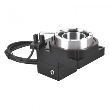
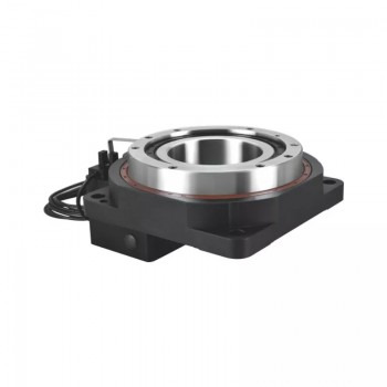
What are the installation precautions of hollow rotary actuators?
1.Introduction to the structure of hollow rotary actuators The main structure of hollow rotary actuators includes conveyor belts, motors, hydraulics and electronic controls. Its moving part is a ring conveyor belt, which can realize the combination of translation and rotation, thereby improving production efficiency. The motor and hydraulic drive parts of the equipment adopt advanced modular design, making the equipment structure more compact and reasonable, with higher reliability and stability.
2.Driving mode of hollow rotary actuators
1.Gear transmission: Power and rotational motion are transmitted through the meshing of gears. Gear transmission can achieve high-precision transmission ratios, which is suitable for heavy equipment and production lines. It has the characteristics of strong load-bearing capacity, mature technology and high reliability.
2.Direct drive technology: The motor is directly connected to the hollow rotary platform to achieve efficient and precise rotational motion. Direct drive technology reduces the intermediate transmission links and improves energy utilization. At the same time, it has high precision and stability and is easy to maintain. 3. Belt drive: The belt is used to drive the hollow rotary platform, which is suitable for small and medium-sized rotary platforms and has the advantages of simple structure and convenient maintenance. 4. Electric drive: The electric motor is used to directly drive the hollow rotary platform, which has the advantages of high transmission efficiency and low noise, and is suitable for small and medium-sized rotary platforms.
3.Technical advantages of hollow rotary actuators 1. High precision and high efficiency: The hollow rotary actuator adopts a precise control system and a high-precision servo motor to achieve high positioning repeatability and accuracy. For example, in the field of semiconductor wafer inspection, the hollow rotary platform can achieve a positioning accuracy of ±5 arc seconds, ensuring that the million-pixel inspection equipment can operate stably at nanometer resolution. 2. High load-bearing capacity and stability: The design of the hollow rotary actuator makes it have high load-bearing capacity. For example, some models of hollow rotary platforms can easily carry 150kg of precision inspection instruments to complete 360° scanning without dead angles. In addition, its rigidity performance is also excellent. The turntable is supported by a set of precision cross roller bearings, which can withstand various torques such as radial, axial, and overturning. The rigidity is more than 10 times that of traditional bearings. 3. Compact structure and flexibility: The hollow rotary actuator adopts a hollow structure design, which makes the equipment compact and occupies a small area, suitable for space-constrained application scenarios. At the same time, its modular design allows for quick replacement of the end effector, which is convenient for integrating force control sensors and visual systems to achieve rapid process switching. 4. Wide application scenarios: Hollow rotary actuators are widely used in many fields. For example, in CNC indexing devices, precise indexing control is provided to improve processing accuracy; at the joints of the manipulator, the hollow structure facilitates pipeline layout, making the manipulator move more smoothly and perform complex tasks; in the fourth processing axis of the machine tool, more dimensional processing operations are realized; in the field of military radar, it helps the radar to accurately adjust the angle and improve the detection performance; in the automated production line, it controls the rotation positioning of material transmission and processing links, etc.
4.Precautions for installation of hollow rotary actuators 1. Preparation: Before installation, it is necessary to confirm whether the motor and hollow rotary platform are intact, and check whether the dimensions of each component match, including the positioning boss of the motor, the input shaft and the reducer groove, and the size and matching tolerance. At the same time, clean the installation surface to ensure that there is no anti-rust oil or other impurities. 2. Installation location and environment: The hollow rotary platform should be installed indoors to avoid direct sunlight and heat radiation. The working environment temperature should be between 0-50 degrees, and the temperature below the origin sensor should not exceed 42 degrees. In addition, the working environment should be dry to avoid flammable and explosive gases and dust, oil, splashing water, etc. 3. Connection method: The motor and the rotary platform equipment should be naturally connected to ensure that the concentricity of the reducer output shaft and the motor input shaft is consistent, and the outer flange is parallel. It is forbidden to use tools such as hammers when connecting to prevent excessive axial force or radial force from damaging the bearing or gear. 4. Sealing: Pay special attention to the sealing of the equipment, especially the sealing of the shaft of the servo hollow rotary platform. During installation, the mounting bolts at the diagonal position should be tightened gradually to ensure the internal sealing of the equipment and prevent environmental pollution. 5. Electrical connection: The hollow rotating platform requires power support, so the electrical lines need to be connected during installation. The length and color of the wires should be easy to manage and maintain, and the signal wires should be connected to the controller to ensure the operation control of the equipment. 6. Debugging and inspection: After the installation is completed, perform detailed positioning and precision adjustments to ensure smooth and stable operation of the equipment. Debug and inspect the electrical system to ensure its safety and stability.
Source:https://community.networkofcare.org/blogs/amber_stepper_motor/archive/2025/04/11/what-are-the-installation-precautions-of-hollow-rotary-actuators.aspx
0 notes
Text
youtube
Forceteq® Pro – High-Precision Testing for Consumer Electronics https://www.youtube.com/watch?v=JwsLVII3Stw Today’s consumer electronics – from smartphones and watches to car interiors and remote controls – require precise and consistent tactile feedback. But how can these be tested reliably, automatically and in real time? 👉 The answer: Forceteq® Pro by Jenny Science This application video demonstrates a compact 3-axis system performing automated button testing on various consumer electronics devices, using: ✅ ELAX® Z-axis with integrated Forceteq® force sensor ✅ ROTAX® Rxhq 50 rotary axis for flexible test orientations ✅ LINAX® Lxs 200F60S for dynamic X-axis positioning 🚀 Technology Highlights: • Real-time force measurement from 0.001 N to 300 N – no external electronics required • Force-displacement analysis directly in the servo controller • Pass/fail evaluation in real time • Easy browser-based control via WebMotion • Seamless integration into lab, consumer electronics, and automotive test environments 💡 Typical Use Cases: • Smartphone buttons (e.g. power, volume) • Chronograph pushers (watches) • Steering wheel buttons in vehicles • Additional consumer electronics: game controllers, remotes, wearables • Or maybe… your next test system? 🧪 What would you like to test? Haptic components? Injection pens? We deliver the perfect motion. ============================== ✅ Chapters: 00:00 Introduction – Smart Inspection 00:07 The Future of Inspection 00:28 Force Measurement & Real-Time Analysis 00:39 Versatile Applications ============================== ✅ Useful Links: 🌐 Website: https://ift.tt/yWGxMCf 📧 Email: [email protected] 🔗 LinkedIn: https://www.youtube.com/@JennyScienceAG/?sub_confirmation=1 ============================== ✅ More exciting videos: 👉 Forceteq® in Auto Injector Assembly https://youtu.be/q1Yf5o5HJEc 👉 Introduction to LINAX® Lxs F60S https://youtu.be/SyFWXBQiTzA 👉 Pick & Place with ROTAX® https://youtu.be/pn0wuqfxGig 👉 WebMotion & Gantry Systems Explained https://youtu.be/jzppnUSqErY ============================== ✅ About Jenny Science AG: Jenny Science AG is a forward-thinking, family-owned Swiss company and a leading manufacturer of compact linear motor axes, hollow shaft motors and web-based motion controllers for industrial automation. We develop and produce our products at our headquarters in Rain (LU) with a team of around 65 dedicated professionals. ============================== 🔔 Subscribe now and never miss an innovation: https://www.youtube.com/@JennyScienceAG/?sub_confirmation=1 ============================== 🔖 Hashtags: #JennyScience #ForceteqPro #SmartInspection #Automation #ForceMeasurement #WebMotion #ConsumerElectronics #MedicalDevices #Haptics #Mechatronics #MachineBuilders © Jenny Science AG via Jenny Science AG https://www.youtube.com/channel/UCjWsIm0BVRObYMt9nmyn6ww April 02, 2025 at 03:58PM
#jennyscience#ethernetinstaller#xenaxcontrollers#webmotion#motorcontrol#servocontroller#industrialautomation#motorcontroltechnology#Youtube
0 notes
Text
Global Indoor Micro Dome Cameras Market Consumption Value Analysis 2025-2031
On 2025-3-12 Global Info Research released【Global Indoor Micro Dome Cameras Market 2025 by Manufacturers, Regions, Type and Application, Forecast to 2031】. This report includes an overview of the development of the Indoor Micro Dome Cameras industry chain, the market status of Consumer Electronics (Nickel-Zinc Ferrite Core, Mn-Zn Ferrite Core), Household Appliances (Nickel-Zinc Ferrite Core, Mn-Zn Ferrite Core), and key enterprises in developed and developing market, and analysed the cutting-edge technology, patent, hot applications and market trends of Indoor Micro Dome Cameras. According to our (Global Info Research) latest study, the global Indoor Micro Dome Cameras market size was valued at US$ 232 million in 2024 and is forecast to a readjusted size of USD 313 million by 2031 with a CAGR of 4.1% during review period. Indoor Micro Dome Cameras are a type of compact surveillance camera designed for use in security systems, offering high-quality video surveillance in a discreet and aesthetically pleasing form factor. These cameras are typically small, dome-shaped, and are often used in areas where space is limited or where the camera needs to blend into the environment while still providing effective surveillance. This report is a detailed and comprehensive analysis for global Indoor Micro Dome Cameras market. Both quantitative and qualitative analyses are presented by manufacturers, by region & country, by Type and by Application. As the market is constantly changing, this report explores the competition, supply and demand trends, as well as key factors that contribute to its changing demands across many markets. Company profiles and product examples of selected competitors, along with market share estimates of some of the selected leaders for the year 2025, are provided.
Market segment by Type: Single Sensor、Multi-Sensor Market segment by Application:Offices、Hospitals、Airports、Home、Others Major players covered: Honeywell、Bosch、Hanwha Vision、Axis Communications (Canon)、IDIS、Tyco Illustra (Johnson Controls)、Hikvision、AV Costar (Costar)、Rhombus Systems、Anviz、Vicon Industries、MOBOTIX (Konica Minolta)、Synectics、Avigilon (Motorola)、Stortech Electronics
Market segment by region, regional analysis covers: North America (United States, Canada and Mexico), Europe (Germany, France, United Kingdom, Russia, Italy, and Rest of Europe), Asia-Pacific (China, Japan, Korea, India, Southeast Asia, and Australia),South America (Brazil, Argentina, Colombia, and Rest of South America),Middle East & Africa (Saudi Arabia, UAE, Egypt, South Africa, and Rest of Middle East & Africa). The content of the study subjects, includes a total of 15 chapters: Chapter 1, to describe Indoor Micro Dome Cameras product scope, market overview, market estimation caveats and base year. Chapter 2, to profile the top manufacturers of Indoor Micro Dome Cameras, with price, sales, revenue and global market share of Indoor Micro Dome Cameras from 2020 to 2025. Chapter 3, the Indoor Micro Dome Cameras competitive situation, sales quantity, revenue and global market share of top manufacturers are analyzed emphatically by landscape contrast. Chapter 4, the Indoor Micro Dome Cameras breakdown data are shown at the regional level, to show the sales quantity, consumption value and growth by regions, from 2020 to 2031. Chapter 5 and 6, to segment the sales by Type and application, with sales market share and growth rate by type, application, from 2020 to 2031. Chapter 7, 8, 9, 10 and 11, to break the sales data at the country level, with sales quantity, consumption value and market share for key countries in the world, from 2020 to 2024.and Indoor Micro Dome Cameras market forecast, by regions, type and application, with sales and revenue, from 2025 to 2031. Chapter 12, market dynamics, drivers, restraints, trends and Porters Five Forces analysis. Chapter 13, the key raw materials and key suppliers, and industry chain of Indoor Micro Dome Cameras. Chapter 14 and 15, to describe Indoor Micro Dome Cameras sales channel, distributors, customers, research findings and conclusion.
Data Sources: Via authorized organizations:customs statistics, industrial associations, relevant international societies, and academic publications etc. Via trusted Internet sources.Such as industry news, publications on this industry, annual reports of public companies, Bloomberg Business, Wind Info, Hoovers, Factiva (Dow Jones & Company), Trading Economics, News Network, Statista, Federal Reserve Economic Data, BIS Statistics, ICIS, Companies House Documentsm, investor presentations, SEC filings of companies, etc. Via interviews. Our interviewees includes manufacturers, related companies, industry experts, distributors, business (sales) staff, directors, CEO, marketing executives, executives from related industries/organizations, customers and raw material suppliers to obtain the latest information on the primary market; Via data exchange. We have been consulting in this industry for 16 years and have collaborations with the players in this field. Thus, we get access to (part of) their unpublished data, by exchanging with them the data we have.
From our partners.We have information agencies as partners and they are located worldwide, thus we get (or purchase) the latest data from them. Via our long-term tracking and gathering of data from this industry.We have a database that contains history data regarding the market.
Global Info Research is a company that digs deep into global industry information to support enterprises with market strategies and in-depth market development analysis reports. We provides market information consulting services in the global region to support enterprise strategic planning and official information reporting, and focuses on customized research, management consulting, IPO consulting, industry chain research, database and top industry services. At the same time, Global Info Research is also a report publisher, a customer and an interest-based suppliers, and is trusted by more than 30,000 companies around the world. We will always carry out all aspects of our business with excellent expertise and experience.
0 notes
Text
ADXL335 Module
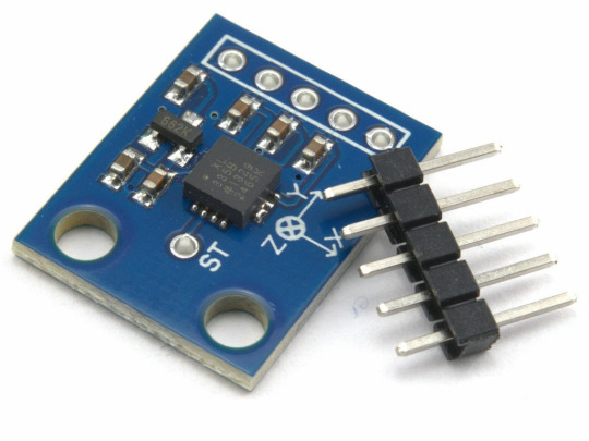
The ADXL335 Module is a compact and energy-efficient 3-axis accelerometer that provides signal conditioned voltage outputs. ADXL335 Module has a minimum full-scale range of ±3 g for accurately measuring acceleration.
This breakout board has the capability to measure both static gravity acceleration in tilt-sensing scenarios, as well as dynamic acceleration caused by movement, impact, or tremors. It is equipped with a built-in voltage regulator and operates seamlessly at 3.3V and 5V (3-5V).
An accelerometer is an electro-mechanical device capable of measuring both static and dynamic acceleration forces. This includes the constant force of gravity acting on your feet, as well as any movement or vibrations that may affect the device.
Systems such as FPV, RC, and Robots.
Navigation systems that utilize GPS technology
Acknowledging and recording the effects.
Devices used for gaming and virtual reality experiences
Features that are activated by movement.
Efficient energy conservation for portable devices.
Monitoring and compensating for vibrations
The detection of free-fall.
Detecting 6D orientation
The characteristics include:
One feature on the board is a Low Dropout (LDO) Voltage Regulator.
Can be connected to either a 3V3 or 5V Microcontroller.
With an ultra-low power consumption rate of only 40uA in measurement mode and an impressive 0.1uA in standby at 2.5V, this device ensures efficiency without compromising on performance.
This feature includes the ability to detect taps and double taps.
A feature for detecting free-fall is included.
The analog output has been successfully connected to the device and is now functioning properly.
Incorporate an ultra low noise linear LDO voltage regulator.
The device contains built-in onboard filters that effectively minimize noise from the motor and other high current electronics.
All sensors on the I2C bus
By using a soldered jumper, it is simple to choose two I2C addresses for the MPU6050.
The LED indicating power.
Incorporate a Logic level converter for I2C connectivity.
Optimized for 5V logic
1 note
·
View note
Text
Global defense Inertial Measurement Unit market reports
A device called an Inertial Measurement Unit (IMU) uses accelerometers and gyroscopes to measure and report force, respectively, and angular rate. Defense inertial measurement units monitor a number of important factors, two of which are the specific gravity and the angular rate of an object. It should be noted that a magnetometer, which measures the magnetic field surrounding the system, is an optional part of this arrangement. By combining a magnetometer into a Defence Inertial Unit, which filters algorithms to determine orientation information results in a device, an apparatus known as an Attitude and Heading Reference Systems (ARHS) is constructed.
One inertial sensor may be able to perceive just measurements along or around one axis, according to the general operation of an inertial measurement unit. To get a three-dimensional solution, three different inertial sensors have to be mounted in an orthogonal cluster, or triad. This trio of inertial sensors arranged in a triad is referred to as a 3-axis inertial sensor since each of the three axes may yield a single measurement from the sensors. This kind of inertial system, which provides two independent measures along each of the three axes for a total of six measurements, is called a 6-axis system. It consists of a 3-axis accelerometer and 3-axis gyroscope.
Main elements propelling the market's expansion:
The market for inertial measurement units is expected to rise as a result of the growing use of autonomous cars and advanced driver assistance systems (ADAS) in both the defense and commercial sectors. The demand for MEMS-based IMU technology is increased by the global defense Inertial Measurement Unit market reports ability to display the precise location of the automotive system in real-time.
Trends impacting the market's expansion:
One of the primary drivers of the growth of the defense inertial measurement units market is the growing use of gyroscopes in the defense industry. The instrument is used to both stabilize the angular velocity and measure the precise velocity. The demand for MEMS-based technology, which enables end users in the commercial automobile and defense sectors to get exact information about their surroundings, is driving the overall growth dynamics.
Dynamics of the Market:
The defense inertial measurement unit is expected to have higher research-based expenditure, which would propel market expansion. The expansion of defense inertial measurement units is also expected to be driven by the rising market penetration of unmanned systems. IMUs are currently widely used in Unmanned Aerial Vehicles (UAVs), AGVs, and other robots that need to know their altitude and position in space.
Advancements:
Another area of research using inertial measurement units that is becoming more and more prominent is collaborative robot research. The focus of the study is on the positioning of human workers who collaborate with collaborative robots. The deployment of human workers is required to achieve safe human-robot cooperation. Vision and ranging sensors will be used to determine the workers' positions. On the other hand, IMU can be used to determine both the operator's position and the altitude. Compared to the previous technology, which frequently only recorded the operator's approximate location and direction, the motion capture system based on IMUs can follow the movement of the operator's full body, making it more appropriate for human-robot collaboration.
0 notes
Text

You may have noticed that the Revopoint POP 3, among other things, is packing an inertial measurement unit, commonly shortened to IMU, inside it. So, IMUs aren’t exactly new technology, having been around since the 1940s and even used in the Apollo missions to help guide the rockets. But, like many technologies, they have shrunk to small chip sizes over time, which has helped them spread across a whole gamut of devices, from drones to your phone to even Nintendo Wii controllers. So let’s look at what’s an IMU and how it helps POP 3 scan better.
What Do IMUs Do?
In a nutshell, IMUs are used to track position, orientation, and velocity. And devices with an IMU typically use this data for navigation as it helps a device know where it is. Or if you’ve ever checked your step count on your phone, this data was likely obtained from the device’s IMU, which recorded the phone’s motion as you walked.
How Does It Work?
Inside the IMU are tiny gyroscopes, accelerometers, and sometimes magnetometers to measure angular attitude, acceleration, and magnetic field, respectively. In POP 3’s case, there are 9 sensors, one of each for each axis, to detect the pitch, roll, and yaw as you move POP 3. Then an algorithm analyzes this data to determine the scanners’ speed and direction.
Gyroscopes
Measures the angular attitude of POP 3. The tiny gyroscopes in an IMU work through small masses vibrating with an equal amount in opposite directions. Then the Coriolis forces acting on the masses determine the angular attitude.
Accelerometer
As the name suggests, this measures the acceleration of a device as you move it. It does it by using something called the Piezoelectric effect, which uses microscopic crystal structures to generate a voltage when they vibrate. And the level of voltage generated indicates the acceleration occurring to the device.
Magnetometer
Otherwise known as an electronic compass, it measures the strength and directions of the Earth’s magnetic field. And are in IMUs to provide a point of reference that the gyroscope and accelerometer use to compare their results against. This helps to prevent the IMU positioning from drifting too much. However, even with the help of a magnetometer, IMUs still sometimes need to be recalibrated to maintain accuracy.
How Does an IMU Help a 3D Scanner?
POP 3’s IMU helps you scan in a few ways. Firstly, it helps to smooth the frame stitching as you scan because now the scanner knows its precise position for each capture frame, making it easier to stitch the frames together accurately by checking their positional data.
Secondly, POP 3 is better at dealing with shaking and being moved too quickly when scanning by hand because it can use the IMU data to work out if it’s in an unexpected position caused by either of these and then delete the faulty frames caused by it.
1 note
·
View note
Text
Multi Axis Linear Systems Are Working in Italy Client's Stores
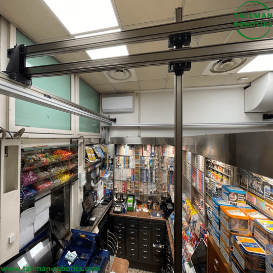
Multi-axis linear systems, also known as multi-axis linear stages or multi-axis positioning systems, are mechanical systems designed to provide precise and controlled movement in multiple linear directions. These systems are commonly used in various applications where precise positioning and motion control are required, such as industrial automation, manufacturing, semiconductor manufacturing, microscopy, and research.


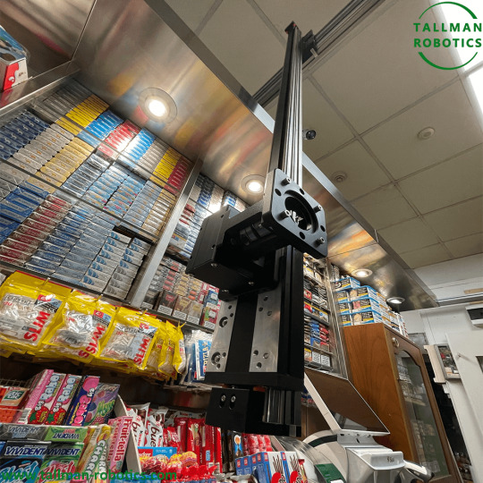

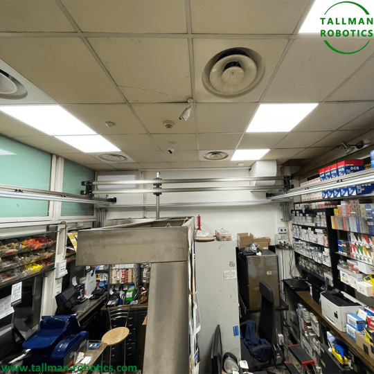


A multi-axis linear module typically consists of multiple linear stages or actuators that are combined and coordinated to enable movement in two or more linear axes. These axes can be orthogonal (perpendicular) to each other or arranged in any other desired configuration. The number of axes can vary depending on the specific application requirements. Each linear stage in a multi-axis system is equipped with a motor or actuator that generates the necessary force to move the stage along its linear path. The stages are usually guided by precision linear bearings or linear guides to ensure smooth and accurate motion. The stages may also incorporate position feedback sensors, such as encoders, to provide feedback on the position and enable closed-loop control. To achieve coordinated motion in multiple axes, a multi-axis linear modules relies on a control system. The control system coordinates the movement of each stage, ensuring synchronized motion and accurate positioning. It receives input commands or trajectories and translates them into appropriate control signals for each axis. The control system may include a motion controller, servo drives, and software algorithms for trajectory planning and motion synchronization. Multi-axis linear systems offer several advantages, including: 1. Precise positioning: These systems provide high-precision positioning capability, allowing for accurate alignment and motion control. 2. Flexibility: Multi-axis systems can be customized and configured to meet specific application requirements, such as the number of axes, travel range, load capacity, and motion profiles. 3. Compact design: The integration of multiple axes into a single system results in a compact and space-saving design, making them suitable for applications with limited space. 4. Increased throughput: By enabling simultaneous motion in multiple axes, multi-axis systems can improve overall productivity and throughput in automated processes. 5. Versatility: These systems can be used in various applications, including pick-and-place operations, assembly, inspection, testing, and scanning. It's important to note that the specific characteristics and capabilities of multi-axis linear modules can vary depending on the manufacturer, design, and intended application. Therefore, it's recommended to consult with system suppliers or experts to determine the most suitable system for a particular use case. You are welcome to https://www.youtube.com/@tallmanrobotics to watch our video centre for more projects or visit our website to check other series or load down e-catalogues for further technical data. Read the full article
#Cartesianmulti-axissystems#linearsystems#MiniatureMulti-AxisSystems#Multi-Axis(XY)LinearActuator#multi-axislinearstages#Multi-AxisPositioningSystems#Multi-AxisSystems#Multi-axissystemswithlinearmotors
0 notes