#AC and DC Motor Testing
Explore tagged Tumblr posts
Visit Tumblr Blog
Explore Tumblr blogs with no restrictions, modern design and the best experience.
Last Seen Tumblr Blogs


Fun Fact
The Tumblr office adopted Tommy, an 11-year-old Pomeranian.
Text
Motors are essential to almost every industry, right from manufacturing to utilities. Without them, many processes would come to a standstill. However, motors require constant supervision to ensure they operate smoothly without frequent breakdowns. That’s where motor testing becomes crucial, as it helps in diagnosing issues early, monitoring motor health, and ensuring performance and safety standards are met.
#Types of Motor Testing#Motor Insulation Testing#Vibration Analysis for Motors#Motor Condition Monitoring#AC and DC Motor Testing#Motor Testing Equipment#Crest Test Systems
0 notes
Text
Best Practices for Safe and Efficient LV Electrical Installations in 2025

Introduction
Low Voltage (LV) electrical installations are the backbone of safe and reliable power distribution in residential, commercial, and industrial settings. In 2025, as energy demands rise and smart technologies evolve, following best practices in LV installations is more important than ever to ensure safety, efficiency, and compliance.
This blog outlines the latest best practices for designing, installing, and maintaining LV electrical systems according to international standards and industry trends.
What Is an LV Electrical Installation?
LV (Low Voltage) refers to electrical systems that operate at voltages up to 1000V AC or 1500V DC. These installations include:
· Electrical panels and switchboards
· Distribution circuits
· Lighting systems
· Sockets and fixed appliances
· Motor control systems
Proper LV installation ensures that power is distributed safely and efficiently without risk of fire, equipment failure, or personnel injury.
Why Best Practices Matter in 2025
In the age of smart buildings, renewable integration, and digital energy management, the quality of your LV installation affects:
· Operational reliability
· Energy efficiency
· System lifespan
· User safety
· Regulatory compliance
Failing to adhere to best practices can result in costly downtime, legal penalties, and even life-threatening hazards.
Top Best Practices for Safe and Efficient LV Electrical Installations
1. Conduct Detailed Load Analysis
Before starting any LV installation, carry out a comprehensive load assessment to determine the power requirements, load types, and future expansion needs. This ensures:
· Proper cable sizing
· Correct protection device selection
· Optimized system capacity
Use load flow software tools and factor in diversity and demand coefficients for accuracy.
2. Follow International Standards (IEC, NEC)
Compliance with recognized standards ensures installations meet safety and performance benchmarks. Key references include:
· IEC 60364 for LV electrical installations
· NEC (NFPA 70) for code-compliant wiring in the U.S.
· ISO 50001 for energy management integration
Also, refer to local electrical regulations where applicable.
3. Use Certified, High-Quality Components
Always use LV components from certified manufacturers — this includes:
· Circuit breakers (MCCBs/MCBs)
· Residual current devices (RCDs)
· Surge protection devices (SPDs)
· Busbars, cables, and enclosures
Poor-quality components may not withstand fault conditions, leading to short circuits, fires, or system failure.
4. Ensure Proper Cable Management and Sizing
Correct cable selection and layout are critical:
· Size cables based on current capacity, voltage drop, and ambient temperature
· Use LSZH (Low Smoke Zero Halogen) cables for fire safety
· Label and route cables cleanly using trays, ducts, and tie-downs
Improper cable management is a leading cause of overheating and system inefficiency.
5. Install Proper Earthing and Grounding Systems
An effective earthing system protects against:
· Electric shock
· Equipment damage
· Lightning surges
Use TT, TN, or IT systems as per the application and ensure resistance values are within acceptable limits (e.g., <1 ohm for sensitive equipment).
6. Use Protection Coordination and Selectivity
Install protective devices in a coordinated hierarchy to ensure:
· Quick isolation of faults
· Minimal disruption to unaffected areas
· Avoidance of cascading tripping
Selectivity between breakers and fuses enhances safety and ensures continuity of service.
7. Integrate Smart Monitoring and Control
Modern LV installations benefit from IoT-enabled devices and energy monitoring software. This helps with:
· Real-time energy usage tracking
· Predictive maintenance alerts
· Power quality monitoring
· Remote switching and control
Smart LV systems are increasingly used in data centers, green buildings, and industrial automation setups.
8. Conduct Periodic Testing and Maintenance
Post-installation, regular inspection and testing ensure sustained safety and performance. Best practices include:
· Thermal imaging to detect overheating
· Insulation resistance testing
· RCD trip time checks
· Earth loop impedance measurement
Document all tests and create a preventive maintenance schedule based on manufacturer recommendations and operating conditions.
Common Mistakes to Avoid
· Overloading circuits without upgrading breakers
· Skipping grounding in temporary setups
· Using outdated wiring diagrams
· Mixing incompatible components
· Neglecting ventilation in panel enclosures
Conclusion
Safe and efficient LV electrical installations in 2025 require more than just technical knowledge — they demand a proactive approach that combines regulatory compliance, technology integration, and quality workmanship. By following these best practices, contractors and facility managers can minimize risks, optimize performance, and build future-ready electrical systems.
Whether you’re designing a commercial building, upgrading an industrial site, or installing a smart home system, investing in safe LV practices today is the smartest move for tomorrow.
Connect With Us
Whether you’re a project engineer, contractor, facility manager, or developer — Almond Enterprise is ready to support your next electrical challenge with confidence and capability.
🔗 Visit: www.almondenterprise.com 📞 Contact: [email protected] | +974 33858416
6 notes
·
View notes
Text
F1's DC/AC: Assault & Battery
Formula 1 teams source batteries for their power units, specifically the Energy Store (ES) component, from specialized manufacturers and in-house development, driven by the sport’s stringent performance and safety requirements. The disposal of used batteries follows strict regulations to ensure environmental responsibility, given their hazardous materials. Below is a detailed breakdown:
Sourcing of Batteries for Formula 1 Power Units
Specialized Battery Manufacturers:
Companies like Saft, a leader in high-performance batteries, have historically supplied F1 teams with lithium-ion batteries for the Energy Recovery System (ERS). Saft’s experience, including work on defense projects like the Lockheed Martin F-35, has been adapted for F1’s extreme conditions.
About:Energy, a battery testing and software specialist, collaborates with F1 teams to develop and optimize battery performance through simulation and testing, focusing on power density and degradation.
Other suppliers, such as Marelli, provide components like the Motor Generator Unit (MGU) and associated battery systems, tailoring designs to team specifications.
In-House Development by Power Unit Manufacturers:
Major power unit suppliers—Mercedes, Ferrari, Honda, Audi, and Red Bull Powertrains (with Ford)—often develop batteries in-house or in close partnership with specialists. For example:
Mercedes High Performance Powertrains (HPP) in Brixworth, UK, integrates battery development into its power unit program, leveraging expertise from the turbo-hybrid era.
Ferrari designs its own batteries in Maranello, aligning with its power unit strategy to supply its factory team and customers like Haas and Cadillac.
Honda has advanced lightweight battery designs, achieving significant weight reductions (up to 5kg) for performance gains.
These manufacturers work with advanced lithium-ion chemistries, optimizing for high power density (up to 350kW in 2026 regulations) and energy recovery (up to 9MJ per lap).
Collaborative Innovation:
Teams and suppliers push boundaries in battery chemistry and design, exploring formats like cylindrical, pouch, or prismatic cells to balance energy density, weight (20-25kg regulatory limit), and packaging within the chassis.
Emerging technologies, such as solid-state batteries, are under consideration for future F1 applications, offering potential improvements in lifetime and energy density.
Partnerships with academic institutions, like Imperial College London, aid in refining battery performance for motorsport.
Regulatory Compliance:
Batteries must meet FIA safety standards, including UN38.3 for lithium-ion transport and crash test requirements to prevent dangerous reactions. These regulations influence sourcing decisions, as only certified suppliers can meet such demands.
The FIA’s 2026 regulations, emphasizing a 50/50 power split between internal combustion and electric systems, have spurred investment in battery development, attracting new manufacturers like Audi and Ford.
Disposal of Used Batteries
Regulatory Limits on Battery Usage:
FIA rules limit teams to a set number of Energy Stores per season (currently four, reducing to two in future seasons) to control costs and environmental impact. Exceeding this incurs grid penalties, incentivizing durable designs.
Batteries are designed to withstand intense charge-discharge cycles (10-15 per lap, depending on the circuit), but degradation over a season necessitates replacement.
Recycling and Disposal Processes:
Hazardous Material Handling: Lithium-ion batteries contain chemicals that pose environmental risks if mishandled. F1 teams, operating under EU and international regulations, partner with certified recycling facilities to manage disposal. The EU Battery Directive (2006/66/EC) mandates recycling to recover materials like lithium, cobalt, and nickel.
Specialized Recycling Partners: Companies like Umicore and Redwood Materials (common in automotive sectors) recycle lithium-ion batteries, extracting valuable metals for reuse in new batteries or other applications. While F1-specific partnerships are not publicly detailed, teams likely use similar services given the high-value materials involved.
Closed-Loop Systems: Some manufacturers, like Saft, integrate recycling into their supply chains, repurposing materials from used batteries to reduce waste and costs. This aligns with F1’s push for sustainability, including 100% sustainable fuels by 2026.
Repurposing: Degraded F1 batteries, which no longer meet the sport’s performance demands, may be repurposed for less demanding applications, such as energy storage systems or testing rigs, before final recycling. This practice is common in motorsport and automotive industries.
Environmental Considerations:
The FIA and F1 emphasize sustainability, with initiatives like sustainable fuels and increased hybrid efficiency reducing the sport’s carbon footprint. Battery disposal is part of this, with teams required to adhere to strict environmental protocols.
The high energy density and specialized chemistry of F1 batteries (100-275Wh/kg) make recycling complex but critical to avoid landfill waste and comply with regulations.
Challenges and Innovations:
The 2026 regulations, increasing battery power to 350kW and energy recovery to 9MJ per lap, will intensify battery wear, raising disposal frequency. Teams are exploring chemistries that minimize degradation to extend battery life and reduce waste.
Research into fast-charging and durable batteries aims to lower the environmental impact by reducing the need for oversized batteries, which add weight and disposal burdens.
Critical Notes
Limited Public Data: Exact suppliers and disposal partners for each team are closely guarded due to F1’s competitive nature. Information is often proprietary, with teams like Ferrari and Mercedes only broadly acknowledging in-house or specialist involvement.
Sustainability Push: F1’s commitment to net-zero by 2030 drives innovation in battery recycling and sustainable sourcing, but the sport’s high-performance demands create unique challenges compared to road-car battery systems.
Speculative Future: Solid-state batteries or alternative chemistries could reduce disposal issues by offering longer lifespans, but these are not yet standard in F1.
In summary, F1 teams source batteries from elite suppliers like Saft and through in-house programs at manufacturers like Mercedes and Ferrari, focusing on cutting-edge lithium-ion technology. Used batteries are recycled through specialized facilities to recover materials, aligning with environmental regulations and F1’s sustainability goals. The lack of specific team-by-team disposal data reflects the sport’s secrecy, but industry-standard practices provide a reliable framework.

3 notes
·
View notes
Text
How to Do a Load Bank Test on a Generator?|EMAX Load Bank
Generators are critical assets for businesses and homes, providing essential backup power during outages. To ensure that a generator will perform as needed during an emergency, it is crucial to conduct regular maintenance and testing. One of the most effective ways to test a generator's performance is through a load bank test. This comprehensive guide will walk you through the steps of performing a load bank test on a generator, ensuring optimal performance and reliability.

What is a Load Bank Test?
A load bank test involves using a device known as a load bank to simulate electrical loads that the generator might encounter during operation. The test ensures the generator can handle its full rated capacity and helps identify any issues that could affect performance. Load bank tests are essential for maintaining the health of standby generators, ensuring they can provide reliable power when needed.

Why Perform a Load Bank Test?
Performing a load bank test has several benefits:
Verification of Performance: Ensures the generator can handle its maximum load without issues.
Identifying Potential Problems: Helps detect issues like wet stacking in diesel generators, which occurs when the engine doesn't reach optimal temperature.
Improved Reliability: Regular testing ensures the generator is reliable and ready for emergencies.
Compliance with Regulations: Some industries require regular load testing to comply with safety and operational regulations.

Types of Load Bank Tests
There are three primary types of load bank tests:
Resistive Load Bank Test: Simulates real-world loads such as lighting and heating. It is the most common type of test.
Reactive Load Bank Test: Simulates loads that include inductive (motors, transformers) and capacitive (capacitors) components.
Combined Load Bank Test: Uses both resistive and reactive loads to simulate the most realistic operating conditions.

Preparation for Load Bank Testing
Before performing a load bank test, follow these preparatory steps:
1. Review Manufacturer Guidelines
Consult the generator’s manual for specific instructions and safety precautions related to load bank testing. Adhering to manufacturer guidelines is crucial to avoid voiding warranties or causing damage.
2. Inspect the Generator
Conduct a thorough visual inspection of the generator. Look for any signs of wear, leaks, or damage. Ensure that the fuel, oil, and coolant levels are adequate and that all connections are secure.
3. Ensure Adequate Ventilation
Load testing generates a significant amount of heat. Ensure that the testing area is well-ventilated to dissipate heat and prevent overheating.
4. Gather Necessary Equipment
Ensure you have the following equipment ready:
Load bank unit
Load cables
Personal protective equipment (PPE)
Monitoring devices (e.g., multimeters, temperature sensors)

Step-by-Step Guide to Performing a Load Bank Test
Step 1: Connect the Load Bank to the Generator
Safety First: Wear appropriate PPE, including gloves and safety glasses.
Shut Down the Generator: Ensure the generator is turned off before making any connections.
Connect Cables: Attach the load bank cables to the generator’s output terminals. Ensure that the connections are secure to prevent arcing or loose connections.
Verify Connections: Double-check all connections to ensure they are tight and correctly aligned.
Step 2: Start the Generator
Start-Up: Follow the standard procedure to start the generator.
Warm-Up Period: Allow the generator to run for a few minutes to reach its normal operating temperature. This helps in accurate load testing.
Step 3: Gradually Apply Load
Incremental Load: Begin by applying a small load incrementally using the load bank. This gradual increase helps prevent sudden surges that could damage the generator.
Monitor Parameters: As you increase the load, continuously monitor the generator’s parameters, such as voltage, current, frequency, and temperature.
Stabilize Each Load Level: Allow the generator to stabilize at each load level for a few minutes. This helps in identifying any potential issues early.
Step 4: Apply Full Load
Full Load Application: Once the generator has stabilized at incremental loads, apply the full rated load. This step is crucial as it tests the generator’s ability to handle its maximum capacity.
Continuous Monitoring: Keep monitoring all critical parameters. Look for any signs of overheating, abnormal vibrations, or unusual noises.
Step 5: Maintain Full Load
Duration: Maintain the full load for a specified duration, typically around 30 minutes to an hour. This duration helps in identifying any long-term issues.
Document Readings: Record all readings and observations during the test. This documentation is valuable for future reference and maintenance planning.
Step 6: Gradually Reduce Load
Incremental Reduction: Gradually reduce the load in small increments until the generator is running without any load.
Cooldown Period: Allow the generator to run without load for a few minutes to cool down gradually.
Step 7: Shut Down and Disconnect
Shutdown Procedure: Follow the standard shutdown procedure for the generator.
Disconnect Cables: Safely disconnect the load bank cables from the generator. Ensure that all connections are secure and the generator is back to its standby mode.

Post-Test Analysis and Maintenance
Review Test Data
Analyze the data collected during the test. Look for any anomalies or deviations from normal operating parameters. Identifying trends or issues early can prevent major problems later.
Inspect Generator
Conduct a post-test inspection of the generator. Look for any signs of stress or damage caused by the load test. Check for leaks, unusual wear, or any other abnormalities.
Perform Necessary Maintenance
Based on the test results and inspection, perform any necessary maintenance. This may include changing filters, topping off fluids, tightening connections, or addressing any identified issues.
Update Maintenance Records
Keep detailed records of the load bank test, including all readings, observations, and maintenance actions taken. This information is crucial for tracking the generator’s performance over time and planning future maintenance.

Safety Considerations
Safety is paramount when performing a load bank test. Here are some key safety considerations:
Follow Manufacturer Guidelines: Always adhere to the generator and load bank manufacturer’s safety instructions.
Use PPE: Wear appropriate personal protective equipment, such as gloves, safety glasses, and hearing protection.
Secure Connections: Ensure all electrical connections are secure and correctly made to prevent electrical hazards.
Monitor Continuously: Never leave the generator unattended during the test. Continuous monitoring is essential to identify and address issues promptly.
Adequate Ventilation: Ensure the testing area is well-ventilated to dissipate heat generated during the test.
Conclusion
A load bank test is an essential part of generator maintenance, ensuring that your generator is capable of handling its full rated capacity and ready to provide reliable backup power during emergencies. By following the steps outlined in this guide, you can perform a load bank test safely and effectively. Regular testing, combined with routine maintenance, will help extend the life of your generator and ensure its reliability when you need it most.
Maintaining detailed records of each load bank test, addressing any identified issues promptly, and adhering to safety protocols will contribute to the long-term performance and reliability of your generator. By investing time and effort into regular load bank testing, you can have peace of mind knowing that your generator is ready to perform at its best when it matters most.
2 notes
·
View notes
Text
How Do Power, Motor & Robotics Development Tools Drive Innovation in Automation?

Introduction to Modern Development Ecosystems
As the era of intelligent machines, automation, and smart manufacturing continues to advance, Power, Motor & Robotics Development Tools have emerged as essential components in transforming ideas into functioning prototypes and commercial solutions. These tools serve as the backbone for developing precise and reliable control systems used in a wide variety of sectors—from industrial robotics to electric mobility.
With the increasing integration of microcontrollers, sensors, thermal management components, and electronic controllers, development tools offer a modular and practical approach to building sophisticated electronic and electromechanical systems.
What Are Power, Motor & Robotics Development Tools?
Power, Motor & Robotics Development Tools consist of hardware kits, interface boards, and control modules designed to help developers and engineers test, prototype, and deploy automated systems with precision and speed. These tools make it possible to manage current, voltage, mechanical motion, and real-time decision-making in a structured and scalable manner.
By combining essential components such as capacitors, fuses, grips, cables, connectors, and switches, these kits simplify complex engineering challenges, allowing smooth integration with controllers, microprocessors, and sensors.
Exploring the Primary Toolsets in the Field
Power Management Development Tools
Efficient energy management is crucial for ensuring stability and performance in any robotic or motor-driven system.
Development boards supporting AC/DC and DC/DC conversion
Voltage regulators and surge protection circuits for safe energy flow
Thermal sensors and oils to maintain system temperature
Battery management ICs to control charge-discharge cycles
High-efficiency transformers and current monitors
Motor Control Development Tools
Motor control kits are built to manage torque, direction, and speed across a range of motor types.
H-bridge motor drivers for bidirectional motor control
Stepper motor controllers with high-precision movement
Brushless DC motor driver modules with thermal protection
Feedback systems using encoders and optical sensors
PWM-based modules for real-time torque adjustment
Robotics Development Tools
Robotics kits merge both mechanical and electronic domains to simulate and deploy automation.
Preassembled robotic arm platforms with programmable joints
Sensor integration boards for object detection, motion sensing, and environmental monitoring
Wireless modules for IoT connectivity using BLE, Wi-Fi, or RF
Microcontroller development platforms for logic execution
Mounting hardware and cable grips for secure installations
Benefits of Using Professional Development Tools
Advanced development kits offer more than just experimentation—they serve as stepping stones to commercial production. These tools minimize development time and maximize productivity.
Enhance system performance with modular plug-and-play designs
Enable easy integration with laptops, diagnostic tools, and controllers
Reduce design errors through pre-tested circuitry and embedded protection
Facilitate rapid software and firmware updates with compatible microcontrollers
Support debugging with LED indicators, thermal pads, and status feedback
Key Applications Across Industries
The adaptability of Power, Motor & Robotics Development Tools makes them suitable for countless industries and applications where intelligent movement and power efficiency are essential.
Industrial robotics and pick-and-place systems for manufacturing automation
Smart agriculture solutions including automated irrigation and drone control
Automotive design for electric vehicle propulsion and battery systems
Aerospace applications for lightweight, compact control mechanisms
Educational platforms promoting STEM learning with hands-on robotics kits
Essential Components that Enhance Development Kits
While the kits come equipped with core tools, several other components are often required to expand capabilities or tailor the kits to specific use cases.
Sensors: From temperature and light to current and magnetic field detection
Connectors and plugs: For flexible integration of external modules
Switches and contactors: For manual or automatic control
Thermal pads and heatsinks: For preventing overheating during operation
Fuses and circuit protection devices: For safeguarding sensitive electronics
LED displays and character LCD modules: For real-time data visualization
How to Choose the Right Tool for Your Project
With a vast array of kits and tools on the market, selecting the right one depends on your application and environment.
Identify whether your project focuses more on power management, motor control, or full robotic systems
Consider compatibility with popular development environments such as Arduino, STM32, or Raspberry Pi
Check the current and voltage ratings to match your load and motor specifications
Evaluate add-on support for wireless communication and real-time data processing
Ensure the tool includes comprehensive documentation and driver libraries for smooth integration
Why Development Tools Are Crucial for Innovation
At the heart of every advanced automation solution is a well-structured foundation built with accurate control and reliable hardware. Development tools help bridge the gap between conceptualization and realization, giving engineers and makers the freedom to innovate and iterate.
Encourage experimentation with minimal risk
Shorten product development cycles significantly
Simplify complex circuit designs through preconfigured modules
Offer scalability for both low-power and high-power applications
Future Scope and Emerging Trends
The future of development tools is headed toward more AI-integrated, real-time adaptive systems capable of learning and adjusting to their environment. Tools that support machine vision, edge computing, and predictive analytics are gaining traction.
AI-powered motion control for robotics
Integration with cloud platforms for remote diagnostics
Advanced motor drivers with feedback-based optimization
Miniaturized power modules for wearable and mobile robotics
Conclusion: Is It Time to Upgrade Your Engineering Toolkit?
If you're aiming to build smarter, faster, and more energy-efficient systems, Power, Motor & Robotics Development Tools are not optional—they’re essential. These kits support you from idea to implementation, offering the flexibility and performance needed in modern-day innovation.
Whether you're developing a prototype for a high-speed robotic arm or integrating power regulation into a smart grid solution, the right development tools empower you to transform challenges into achievements. Take the leap into next-gen automation and electronics by investing in the tools that make engineering smarter, safer, and more efficient.
#Power Motor & Robotics Development Tools#electronic components#technology#electricalparts#halltronics
0 notes
Text
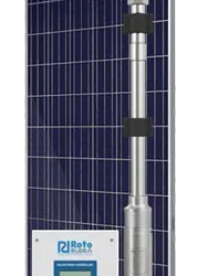
Water Pumping Solutions
When it comes to Water Pumping Solutions, one name stands tall in India’s renewable and sustainable energy sector – ROTO ENERGY SYSTEMS LIMITED. With a legacy of trust, innovation, and engineering brilliance, ROTO ENERGY SYSTEMS LIMITED has revolutionized the way industries and farmers approach modern-day Water Pumping Solutions.
Why Choose Water Pumping Solutions from ROTO ENERGY SYSTEMS LIMITED?
At ROTO ENERGY SYSTEMS LIMITED, our mission is clear – deliver Water Pumping Solutions that are efficient, sustainable, and tailored to India’s diverse needs. Whether you’re a farmer in Punjab, a rural developer in Maharashtra, or an industrial operator in Gujarat, our advanced Water Pumping Solutions are engineered to meet your needs with precision.

Wide Range of Water Pumping Solutions
ROTO ENERGY SYSTEMS LIMITED offers a complete portfolio of Water Pumping Solutions, including:
Solar Water Pumping Solutions
DC Submersible Water Pumping Solutions
AC Solar Water Pumps
Helical Rotor Pumps
Submersible Motors for Water Pumping Systems
Agricultural Water Pumping Solutions
Industrial Water Pumping Solutions
Solar-Powered Water Pumping Solutions – The Future is Here
One of the flagship offerings of ROTO ENERGY SYSTEMS LIMITED is its solar water pumping solutions. These Water Pumping Solutions run entirely on solar energy, ensuring massive savings on electricity bills and promoting green energy. Our solar water pumping systems are ideal for agriculture, remote irrigation, drinking water supply, and more.
Why go solar with ROTO ENERGY SYSTEMS LIMITED?
100% eco-friendly Water Pumping Solutions
Reduced carbon footprint
Zero fuel cost
Easy installation
Government subsidy benefits
Built for India – Water Pumping Solutions that Work Where It Matters
ROTO ENERGY SYSTEMS LIMITED understands the unique challenges of India’s terrain, climate, and water table levels. Our Water Pumping Solutions are tested and validated for:
High groundwater levels
Low-yield wells
Dry-run conditions
Varying voltage supply
Helical Rotor Water Pumping Solutions – Engineered Precision
A special mention goes to our Helical Rotor Water Pumping Solutions, crafted with SS 304/316, specialized rubber stators, and dry-run protection. These precision-engineered Water Pumping Solutions offer smooth, pulsation-free flow even at low water heads and are perfect for high-suction applications.
For More Detail
Contact us:- +91 93112 03301 Visit us:- Water Pumping Solutions Address:- Plot No. 06, Sector-Ecotech XII, Roza Jalalpur Village, Greater Noida, Uttar Pradesh 201308
0 notes
Text
youtube
New BYD Dolphin Surf 2025 Test Drive POV
BYD Dolphin Surf Dimensions & Weight • Length / Width / Height (mm): 3,990 / 1,720 / 1,590 • Wheelbase (mm): 2,500 • Curb Weight (kg): • Active: 1,294 kg • Boost: 1,370 kg • Comfort: 1,390 kg ⚙️ Performance • Drive Type: Front-wheel drive • Top Speed: 150 km/h • Motor Power (kW): • Active: 65 kW • Boost: 65 kW • Comfort: 115 kW • 0–100 km/h Acceleration (s): • Active: 11.1 s • Boost: 12.1 s • Comfort: 9.1 s • Wheel Size (inches): • Active: 15” • Boost: 16” • Comfort: 16” 🔋 Battery & Charging • Battery Type: BYD Blade Battery (LFP) • Battery Capacity (kWh): • Active: 30 kWh • Boost: 43.2 kWh • Comfort: 43.2 kWh • Charging Power: • DC: 65 kW (Active), 85 kW (Boost/Comfort) • AC: 11 kW (all versions) • DC Charging Time (30–80%): • Active: 25 min • Boost/Comfort: 22 min • DC Charging Time (10–80%): • All versions: 30 min 🔌 Range (WLTP) • Combined Range (km): • Active: 220 km • Boost: 322 km • Comfort: 310 km • City Range (WLTP Innerorts, km): • Active: 356 km • Boost: 507 km • Comfort: 460 km

#Romania#BYD#BYD Dolphin Surf#affordable EV#ev test drive#electric hatchback#electric vehicle#energy safety#energy independence#Europe#China#Youtube
1 note
·
View note
Text
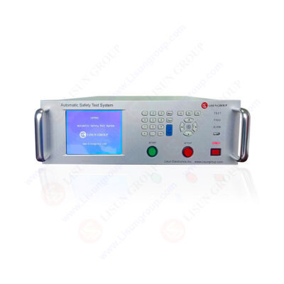
Abstract This paper focuses on the LISUN LS9955 insulation tester, which is an integral part of the Automatic Safety Test System. It delves into the functionality, technical specifications, and applications of this insulation tester in ensuring electrical safety. By analyzing its features and comparing it with industry standards, the paper demonstrates the importance of the LISUN LS9955 insulation tester in various electrical product testing scenarios. Through in – depth research and data presentation, it provides a comprehensive understanding of how this device contributes to maintaining high – level electrical safety. 1. Introduction In the realm of electrical engineering and product safety, ensuring the integrity of insulation is of utmost importance. Electrical insulation serves as a crucial barrier, preventing the flow of electric current where it is not desired, thus safeguarding both human life and electrical equipment. The LISUN LS9955 insulation tester, as part of the Automatic Safety Test System, plays a vital role in this regard. The LISUN LS9955 is not just a simple insulation tester; it is a multi – functional device that combines several key electrical safety tests, including the insulation resistance test (IR). This makes it an essential tool for manufacturers, quality control departments, and research and development laboratories in the electrical industry. It can be used to test a wide range of electrical products, such as lighting fixtures, household appliances, and motor tools, ensuring that they meet strict safety standards. 2. Working Principle of the Insulation Tester in the LISUN LS9955 The insulation resistance test in the LISUN LS9955 is based on the principle of applying a direct – current (DC) voltage across the insulation being tested and measuring the resulting leakage current. According to Ohm’s law, the insulation resistance (R) can be calculated as the ratio of the applied voltage (V) to the measured current (I), i.e.,R=V/I The tester has a specific voltage range for the insulation resistance test, which is DC100 – 1000V. When the voltage is applied, if the insulation is in good condition, the leakage current will be very small, indicating a high insulation resistance. However, if there are defects in the insulation, such as cracks, moisture ingress, or aging, the leakage current will increase, resulting in a lower insulation resistance value. Automatic Safety Test System LS9955 3. Technical Specifications of the LISUN LS9955 Insulation Tester 3.1 Insulation Resistance Test Specifications The LISUN LS9955 insulation tester has an impressive insulation resistance measurement range of 1.00 – 2000MΩ with an accuracy of 5%+0.5MΩ. This wide range allows it to test a variety of electrical products with different insulation requirements. For example, in household appliances, the insulation resistance requirements may vary depending on the type of appliance and its intended use. A refrigerator may have different insulation requirements compared to a toaster, and the LISUN LS9955 can accurately measure the insulation resistance of both. Test Item Range Accuracy Insulation Resistance (IR) 1.00 – 2000MΩ 5%+0.5MΩ Voltage for IR Test DC100 – 1000V – 3.2 Compatibility with Other Tests As part of the Automatic Safety Test System, the LS9955 insulation tester can be used in conjunction with other tests, such as the withstand voltage test, leakage current test, and grounding resistance test. This integrated approach provides a more comprehensive assessment of the electrical safety of a product. For instance, after measuring the insulation resistance, the withstand voltage test can be carried out to check if the insulation can withstand higher voltages without breaking down. Test Item Range Accuracy Withstand Voltage (AC/DC) 100 – 4000V ±(5%+3V) Leakage Current (LLC) 0.10 – 20mA ±(0.3%+5μA) Grounding Resistance (GR) 0 – 600mΩ ±(5%+2mΩ) 4. Applications of the LISUN LS9955 Insulation Tester 4.1 In Production Lines In the manufacturing of electrical products, the LISUN LS9955 insulation tester is widely used on production lines. It helps manufacturers ensure that each product leaving the factory meets the required safety standards. By performing insulation resistance tests at various stages of production, manufacturers can identify and correct insulation – related issues early, reducing the risk of defective products reaching the market. For example, in the production of lighting fixtures, the insulation of the electrical components and the outer casing can be tested to prevent electric shock hazards. 4.2 In Research and Development Laboratories Research and development (R&D) laboratories also benefit greatly from the LISUN LS9955 insulation tester. When developing new electrical products or improving existing ones, R&D engineers need to test the insulation performance to optimize the design. The tester’s accurate measurement capabilities enable engineers to evaluate different insulation materials and designs, leading to the development of more reliable and safer electrical products. For instance, in the development of new types of household appliances, engineers can use the LS9955 to test the insulation of innovative circuit designs. 4.3 In Compliance Testing Compliance with international and national safety standards is mandatory for electrical products. The LISUN LS9955 insulation tester is designed to meet several major safety standards, including IEC/EN 60335 – 1:2023/GB 4706.1 – 2024 “Household and similar electrical appliances – Safety – Part 1: General requirements”, UL 60335:2022 “Standard for Safety of Household and Similar Appliances, Part 1: General Requirements”, and IEC 60598:2024/GB 7000 – 2023 “Luminaires – Part 1: General requirements and tests”. When electrical products are tested for compliance, the accurate results provided by the LS9955 insulation tester are crucial for obtaining the necessary certifications. 5. Comparison with Other Insulation Testers in the Market There are numerous insulation testers available in the market, each with its own set of features and capabilities. The LISUN LS9955 insulation tester stands out in several aspects. Firstly, its multi – functional nature sets it apart from single – function insulation testers. Instead of just measuring insulation resistance, it can perform multiple electrical safety tests, which saves time and cost for users. Secondly, in terms of accuracy, the LS9955’s insulation resistance accuracy of 5%+0.5MΩis competitive. Some other testers may have lower accuracy, which could lead to incorrect assessment of insulation quality. For example, a tester with a lower accuracy may misclassify a product with slightly lower – than – required insulation resistance as compliant, posing a potential safety risk. Finally, the LISUN LS9955 is also equipped with user – friendly features such as a large LCD screen that displays all setting parameters and testing results, and a programmable test mode with 50 groups of settings and 8 test steps per group. These features make it easier for operators to use and customize the testing process compared to some more complex or less – intuitive testers in the market. 6. Challenges and Limitations Although the LISUN LS9955 insulation tester is a highly effective device, it does face some challenges and limitations. One of the challenges is the need for proper calibration. Like any precision measuring instrument, the accuracy of the LS9955 can be affected over time. Regular calibration is required to ensure that the measured values are reliable. However, calibration can be time – consuming and costly, especially for small – scale manufacturers or laboratories with limited resources. Another limitation is related to the testing environment. Extreme environmental conditions, such as high humidity or temperature, can affect the insulation resistance measurement results. For example, in a high – humidity environment, moisture can condense on the insulation surface, increasing the leakage current and giving a false – low insulation resistance reading. Special precautions need to be taken to control the testing environment to obtain accurate results. 7. Future Developments Looking ahead, there are several areas where the LISUN LS9955 insulation tester can be further developed. One possible development is the integration of advanced wireless communication technology. This would allow for remote control and data transfer, enabling more convenient operation and data management. For example, operators could control the tester from a different location in a large factory or transfer test data directly to a central database for analysis. Another area of development could be improving the tester’s ability to handle complex insulation structures. As electrical products become more complex, with new materials and designs, the insulation tester needs to be able to accurately measure the insulation resistance of these complex structures. This may involve the development of new measurement algorithms or sensor technologies. 8. Conclusion The LISUN LS9955 insulation tester is a critical component of the Automatic Safety Test System, playing an essential role in ensuring electrical safety. Its wide range of functions, high – accuracy measurement capabilities, and compliance with international standards make it suitable for various applications in the electrical industry, including production lines, R&D laboratories, and compliance testing. Despite some challenges and limitations, such as calibration requirements and environmental sensitivities, the future development prospects for the LISUN LS9955 insulation tester are promising. With the integration of new technologies and improvements in handling complex insulation structures, it is expected to continue to be a leading – edge device in the field of electrical safety testing, contributing to the development of safer electrical products for consumers worldwide. In conclusion, the LISUN LS9955 insulation tester is an indispensable tool in modern electrical engineering and product safety assessment, and its importance will only grow as the demand for safe electrical products continues to increase. Read the full article
0 notes
Text
SSC JE 2025: Complete Guide with Syllabus for Civil and Electrical Engineering
The Staff Selection Commission (SSC) conducts junior engineer (JE) exam every year for recruitment of engineers to different departments under India's government. The SSC JE 2025 exam is expected to follow a similar pattern as previous years, but with updated courses and guidelines. This article provides detailed information on SSC JE 2025, including the SSC JE 2025 course, qualification and specific details for civil engineering and electrical engineering branches.

What is SSC JE 2025?
SSC JE 2025 is a competitive examination conducted by the Staff Selection Commission to recruit Junior Engineers in government departments like CPWD, MES, BRO, and others. The exam is open for candidates with diplomas or degrees in Civil, Mechanical, or Electrical Engineering.
This is a golden opportunity for aspiring engineers to secure a stable job in the central government with good pay, job security, and career growth.
SSC JE 2025 Eligibility Criteria
Before applying, candidates must ensure they meet the basic eligibility:
Nationality: Must be a citizen of India.
Age Limit: Varies by department, typically between 18 to 32 years. Relaxations apply for reserved categories.
Educational Qualification: Diploma or degree in Civil, Mechanical, or Electrical Engineering from a recognized university.
SSC JE 2025 Exam Pattern
The SSC JE exam is conducted in two phases:
Paper 1 (Objective Type)
General Intelligence and Reasoning – 50 marks
General Awareness – 50 marks
Part A (Civil) or Part B (Electrical/Mechanical) – 100 marks Total: 200 marks | Duration: 2 hours
Paper 2 (Descriptive Type)
Subject-specific (Civil/Electrical/Mechanical) – 300 marks Duration: 2 hours
SSC JE 2025 Syllabus Overview
The SSC JE 2025 syllabus is divided into common subjects and branch-specific subjects. While Paper 1 tests general reasoning and awareness, Paper 2 focuses purely on technical knowledge.
Let’s look at the detailed syllabus for Civil and Electrical Engineering.
SSC JE 2025 Civil Engineering Syllabus
Paper 1 – General Sections : SSC JE 2025 Civil Engineering Syllabus
General Intelligence & Reasoning
Analogies, similarities, differences
Space visualization
Problem-solving, analysis, judgment
Arithmetical reasoning, syllogisms
General Awareness
Current events
India and its neighboring countries
History, culture, geography, economic scene
Scientific Research and Indian Constitution
Paper 1 – Civil Engineering
Building Materials
Estimating, Costing, and Valuation
Surveying
Soil Mechanics
Hydraulics
Irrigation Engineering
Transportation Engineering
Environmental Engineering
Paper 2 – Civil Engineering (Descriptive)
RCC Design
Steel Design
Theory of Structures
Concrete Technology
Water Supply and Sanitation
Highway Engineering
Construction Management
CPM and PERT
Fluid Mechanics
Building Planning and Drawing
SSC JE 2025 Electrical Engineering Syllabus
Paper 1 – General Sections
(Same as above for General Intelligence & Reasoning and General Awareness)
Paper 1 – Electrical Engineering
Basic Concepts of Electrical Engineering
Circuit Law (Ohm’s Law, Kirchhoff’s Law)
Magnetic Circuit
AC Fundamentals
Measurement and Measuring Instruments
Electrical Machines
Fractional Kilowatt Motors and Single Phase Induction Motors
Generation, Transmission, and Distribution
Estimation and Costing
Utilization of Electrical Energy
Basic Electronics
Paper 2 – Electrical Engineering (Descriptive)
Detailed theory of Electrical Machines (DC, AC)
Power Systems and Protection
Transmission Lines and Cables
Control Systems
Electrical Measurements
Power Electronics and Drives
Microprocessors and Digital Electronics
Energy Efficiency and Renewable Sources
Circuit Analysis using Theorems
Tips to Prepare for SSC JE 2025
Understand the Syllabus: Go through the SSC JE 2025 syllabus carefully and mark high-weightage topics.
Follow a Study Schedule: Make a realistic timetable covering theory, practice, and revision.
Solve Previous Year Papers: Analyze past questions to understand the pattern and difficulty level.
Mock Tests: Attempt regular mock tests to improve time management and accuracy.
Use Standard Books: Refer to trusted authors and publications. For Civil, books by EA Publication.
Why SSC JE is a Good Career Option?
Government Job Security: Permanent position under central government departments.
Attractive Pay Scale: Basic pay of Level 6 (Rs. 35,400 – Rs. 1,12,400) plus allowances.
Work-Life Balance: Regular working hours with job satisfaction.
Promotions & Growth: Opportunity to rise to senior technical roles.
Conclusion
The SSC JE 2025 exam offers a prestigious and safe career path for civilian and electric engineers. With the right preparation strategy, SSC JE 2025 Understanding the course and continuous practice, candidates can clean the exam with flying colors.
Be sure to stay up to date with official information from the SSC website and start your preparations to stay ahead of competition quickly. Whether you target the SSC JE 2025 Civil Engineering Plan or SSC JE 2025 Electrical Syllabus, structured preparation is the key to success.
FAQs
Q1. What is the age limit for SSC JE 2025?
The general age limit is 18 to 32 years. However, it may vary depending on the department and category of the candidate. Age relaxation is applicable as per government rules.
Q2. Can diploma holders apply for SSC JE 2025?
Yes, candidates with a diploma in Civil, Electrical, or Mechanical Engineering from a recognized institute can apply.
Q3. Is there any interview in SSC JE 2025?
No, there is no interview. Selection is based on the marks obtained in Paper 1 and Paper 2.
Q4. How many attempts are allowed for SSC JE?
There is no limit on the number of attempts, but candidates must fulfill the age and eligibility criteria.
Q5. Is the SSC JE 2025 syllabus the same for all branches?
No. While the general subjects are the same in Paper 1, the technical syllabus differs for Civil, Mechanical, and Electrical Engineering.
#SSC JE 2025#SSC JE 2025 Syllabus#SSC JE 2025 Civil Engineering Syllabus#SSC JE 2025 Electrical Engineering Syllabus
0 notes
Text
Rolling Door Motor
Automated doors are no longer a luxury—they’re a necessity in modern homes, commercial facilities, and industrial properties. At the heart of any automated rolling door is the rolling door motor. This powerful yet compact device drives the functionality of rolling shutters and doors, ensuring smooth, safe, and reliable operation.
If you're planning to install or upgrade a motorized door system, understanding how rolling door motors work and what options are available is essential. This guide will explain the different types, key features to look for, and how to choose the right one for your needs.
What Is a Rolling Door Motor and How Does It Work?
A rolling door motor is a motorized mechanism that controls the upward and downward movement of a rolling door. It replaces the manual effort traditionally needed to lift or lower heavy rolling doors. When activated via switch, remote control, or app, the motor powers a drive shaft that rotates to roll the door curtain around a barrel, lifting or closing the door.
Key components typically include:
Electric motor
Gear mechanism
Control system (remote, wall switch, or smart controller)
Limit switches for stopping at top and bottom
Manual override in case of power failure
Main Types of Rolling Door Motors
1. Tubular Motors
Tubular motors are installed inside the door barrel. They’re commonly used in residential applications and smaller commercial shutters.
Pros:
Sleek and hidden design
Quiet operation
Easy to install
Best for: Garage doors, small storefront shutters
2. Side Motors
Mounted externally on the side of the door, these are designed for heavy-duty use and high-traffic areas.
Pros:
High load capacity
Easy to access for repairs and maintenance
Best for: Warehouses, industrial rolling doors
3. Central Motors
Central motors are installed in the middle of the door barrel. They offer a balanced mix of strength and affordability.
Pros:
Cost-effective
Suitable for medium-weight doors
Best for: Medium-sized rolling shutters
Key Features to Look For in a Rolling Door Motor
When selecting a rolling door motor, here are the most important features to consider:
1. Load Capacity
Always match the motor capacity to the weight and size of the rolling door. Oversized or undersized motors can lead to failure and safety risks.
2. Power Supply
Choose between:
AC motors: Better for continuous, heavy-duty use
DC motors: Quieter, energy-efficient, and often include battery backup
3. Control Options
Look for control systems that fit your needs—manual switches, wireless remotes, smartphone apps, or even smart home integration.
4. Safety Features
Essential safety elements include:
Emergency manual release
Automatic stop and reverse
Thermal overload protection
Brake system to prevent door drop
5. Weather Resistance
For outdoor installations, ensure the motor is rated for weather exposure, especially in harsh climates.
Buying Tips for Rolling Door Motors
Assess your use case: Are you automating a light-use garage door or a high-use industrial entrance?
Verify warranty and support: A longer warranty and accessible tech support add value.
Buy from reputable brands: Stick with manufacturers known for quality and safety certifications.
Get professional advice: If you're unsure, consult with an installer or supplier to avoid compatibility issues.
Maintenance Tips to Keep Your Motor Running Smoothly
To maximize the lifespan and reliability of your rolling door motor, follow these maintenance best practices:
Lubricate moving parts every few months
Inspect cables, springs, and brackets for wear
Test the motor and safety features monthly
Keep the motor and control box clean and dust-free
Have it professionally serviced annually
Conclusion: A Rolling Door Motor Is a Smart Upgrade
Whether you're automating your home garage or managing a commercial facility, investing in the right rolling door motor can improve safety, convenience, and security. By understanding how these motors work, knowing the different types, and making an informed choice, you’ll ensure your system runs efficiently and reliably for years to come.
1 note
·
View note
Text
Variable Frequency Drive Interview Questions
Variable Frequency Drives (VFDs) are essential components in modern industrial and commercial applications. If you're preparing for a job in automation, control systems, or electrical engineering, you need to be ready to face variable frequency drive interview questions. This article will help you understand what interviewers may ask, and how to answer those questions with technical accuracy.

Variable Frequency Drive Interview Questions
Understanding Variable Frequency Drives
Before diving into variable frequency drive interview questions, let’s clarify what a VFD is. A Variable Frequency Drive is an electronic device that controls the speed and torque of electric motors. It works by varying the frequency and voltage supplied to the motor. VFDs are widely used in HVAC systems, conveyors, pumps, compressors, and many other motor-driven systems. They improve energy efficiency, provide better process control, and extend motor life.
Basic Variable Frequency Drive Interview Questions
Most interviews begin with simple questions. These questions test your basic understanding of VFDs. Let’s take a look: What is a Variable Frequency Drive? A VFD is a power electronic system that controls the speed of an AC motor by adjusting the input frequency and voltage. The core purpose is to match motor speed to load requirements. This helps save energy and reduces mechanical stress. Why do we use Variable Frequency Drives? VFDs offer several benefits: - Energy savings by optimizing motor speed - Smooth start and stop operations - Reduced mechanical wear and tear - Improved process control - Lower maintenance costs What are the main components of a VFD? - Rectifier: Converts AC to DC - DC Bus: Stores DC voltage - Inverter: Converts DC back to variable-frequency AC - Controller: Manages operations based on input signals These components help in controlling both single phase drive and 3 phase frequency drive systems.
Intermediate-Level Variable Frequency Drive Interview Questions
As the interview progresses, you’ll face more technical questions that test your hands-on experience and troubleshooting skills. How does a VFD control motor speed? The VFD adjusts the frequency of the power supplied to the motor. Since the motor speed is directly proportional to the frequency, controlling frequency allows speed control. It also adjusts the voltage to maintain a constant volts-per-hertz (V/f) ratio. What types of motors can be controlled using VFDs? Most VFDs are used with 3 phase frequency drive motors. However, single phase drives are also available for light-duty applications. Typical motors include induction motors, synchronous motors, and permanent magnet motors. What is meant by V/f control in a VFD? V/f control refers to maintaining a constant ratio between voltage and frequency. This is crucial to avoid saturation or under-magnetization of the motor core. It's a common open-loop control method for standard applications. Read the full article
#AutomationEngineer#ControlSystems#ElectricalEngineering#ElectricalJobs#IndustrialAutomation#interviewquestions#MotorControl#powerelectronics#VFD#VFDBasics
0 notes
Text
Different Types of High-Voltage Testing Machine
A high-voltage testing machine is one component of a high-voltage test device that combines the functionality of a voltmeter and an ammeter. Such a machine is applied in the simulation of extreme electrical conditions, calibrating the strength, insulation, and safety of components for high-voltage testing.
From testing whether a circuit breaker testing withstands a more than moderately strong power surge to testing if a traction motor is reliable during high-speed running in a train, the types of high-voltage testing machines are as diverse as their applications. In India, where infrastructure and industrialisation are booming, choosing the correct HV testing machine is critical for businesses that want to acquire a distinctly global value system while keeping costs in check.
Crest Test Systems, a leader in test and measurement solutions, is spearheading the charge by providing innovative high-voltage testing machines to industries across the globe. In this excerpt, we’ll examine the applications of different kinds of high-voltage testing machines, integrating them with the know-how of the industry.
What is a High Voltage Testing Machine?
A high voltage testing machine is a piece of equipment that applies high voltage to electrical parts to test their insulation, performance and safety. Such machines are essential for industries like power distribution, manufacturing, and transportation, where the equipment is required to function reliably under high voltage.
Handling volumetric high voltage, such as >1,000 V AC or 1,500 V DC, is a special forte for the machine. Crest Test Systems, incorporated in 2009, deals with automated HV testing machines which guarantee IEEE compliance and other automated international standards set by IEC.
The high voltage testing machines have unique designs poised to perform specific tasks. Their classification is based on test voltage range, the equipment tested and the type of test performed. Each design is crafted to address industry requirements for ease and accuracy in safety and standards enforcement of system reliability out of routine maintenance and robust type testing.
Different Types of High-Voltage Testing Machines and Their Uses
1. AC High Voltage Testers
As the name suggests, AC testers apply alternating current (AC) at high voltage to test the insulation strength and dielectric properties of a component. Crest Test Systems’ CT-HVT Series is a good example, as it can test up to 100 kV RMS at 50 Hz, having significant output current for high capacitance loads such as cables and transformers. These HV testing machines have touchscreen and digital control interfaces that allow fully automated test cycles with results stored for further analysis.
2. DC High Voltage Testers
DC high voltage testers apply direct current (DC) to check the strength of insulation in equipment associated with high voltage direct current (HVDC) systems, which are increasingly found in renewables or rail network systems. DC testers from Crest Test Systems are available for medium voltage networks, including paper-insulated cables, with controllable and accurate voltage settings.
At Crest Test Systems, we have introduced a new product called HVCT80. This high-performance DC high-voltage tester performs tests up to 80 kV, designed for reliable insulation testing in modern HVDC applications.
3. Impulse Voltage Testers
Impulse voltage testers simulate lightning strikes or switching surges to evaluate the durability of high-voltage equipment under transient conditions. These testers are crucial for assessing components such as transformers and insulators. While Crest Test Systems does not currently manufacture these systems, we can procure and supply them through their OEMs, ensuring quality and performance for your specific testing needs.
4. Partial Discharge (PD) Testers
PD testers help detect early-stage insulation defects that can lead to future failures. They offer non-destructive testing for cables, joints, and terminations, and help in pinpointing fault locations for proactive maintenance. Although not part of our standard product lineup, Crest Test Systems can source these testers directly from OEMs to meet client requirements.
5. Tan Delta/Power Factor Testers
Used for assessing dielectric losses, tan delta testers indicate insulation ageing or degradation in power systems. These tests provide insight into the health and remaining life of insulation in cables, transformers, and rotating machines. While not part of our in-house offerings, Crest Test Systems can arrange for high-accuracy tan delta testers from trusted OEM partners.
Uses of High-Voltage Testing Machines
High voltage testing machines have an array of uses across different sectors and fields that include:
Power Transformers: These power transformers are tested to check their energy transfer and insulation efficiency.
High Voltage Cables: Physical testing of the cable’s insulation and the joints is done to confirm performance.
Switchgear and Circuit breakers: Testing the devices for their dielectric strength and mechanical operations.
Motors and Generators: Test them for insulation resistance and operation reliability.
Research and Development: Studying and examining the efficiency and reliability of a prototype under high voltage.
Conclusion
High voltage testing machines, such as AC and DC testers, impulse, partial discharge, and tan delta testers, are essential in confirming electrical equipment’s safety, reliability, and performance.
Crest Test Systems’ high voltage test equipment is helpful whether you are developing a smart city, running a railway system, or even producing transformers. Our equipment is automated, accurate, and up to international standards, assisting various industries.
Discover our product solutions and select the perfect fit for your testing requirements. Get in touch with us now.
FAQs:
What are the different types of high-voltage testing machines?
AC Hipot testers, DC Hipot testers, impulse testers, partial discharge testers, and insulation resistance testers.
Which industries use high-voltage testing machines?
Power, manufacturing, automotive, railways, and electrical equipment testing.
What are the safety precautions while using high-voltage testing machines?
Use protective gear, ensure grounding, follow lockout-tagout procedures, and maintain safe distances.
Where are high-voltage testing machines used?
In labs, factories, substations, and R&D centres to test cables, transformers, motors, and switchgear.
0 notes
Text
dielectric withstand test

Dielectric Withstand Test: What It Is and Why It Matters
Electrical equipment must not only perform efficiently but also operate safely under a range of conditions. One of the most critical evaluations in ensuring safety and performance is the dielectric withstand test. This test is an essential quality assurance procedure used in the design, manufacturing, and maintenance of electrical and electronic equipment. It helps ensure that insulation systems can handle high voltages without breaking down, reducing the risk of shock hazards, fires, and equipment failure.
Understanding the Dielectric Withstand Test
The dielectric withstand test, also known as a high potential or "hipot" test, assesses the integrity of electrical insulation by applying a voltage higher than normal operating levels to an electrical device. The idea is to confirm that the insulation can resist this elevated voltage without allowing current to pass through. If the insulation breaks down and allows current to leak, the equipment fails the test.
The goal of the dielectric withstand test is not to simulate actual working conditions but to apply a margin of safety to see how well the insulation holds up under stress. This is particularly important in safety-critical systems like medical devices, industrial controls, aerospace equipment, and consumer electronics.
Why the Dielectric Withstand Test Is Necessary
Modern electrical systems often contain tightly packed components and operate in harsh environments. Under such conditions, even minor insulation faults can cause catastrophic failures. The dielectric withstand test serves multiple purposes:
Safety Assurance: Ensures that people using or servicing the equipment are protected from electrical shock.
Quality Control: Detects flaws in manufacturing, such as cracks, voids, or contaminants in insulation.
Regulatory Compliance: Meets industry standards required by international and national safety organizations.
Reliability Testing: Predicts how equipment will perform under real-world electrical stress.
Without conducting this test, manufacturers and engineers could unknowingly release products into the field with hidden weaknesses that only reveal themselves during operation—often with dangerous consequences.
How the Dielectric Withstand Test Works
To perform the dielectric withstand test, a high-voltage power supply is connected between two points—typically, the conductive parts of a device and its insulated housing or ground. The applied voltage can be either AC or DC, depending on the type of equipment being tested and the relevant standard.
During the test, technicians gradually increase the voltage to a predetermined level and hold it for a specific duration, usually one to sixty seconds. A sensitive current meter monitors any leakage current. If the current stays below the allowed limit, the device passes. If it exceeds the limit or if insulation breakdown occurs, the test is failed.
The most common test parameters include:
Test Voltage Level: Generally set at twice the rated voltage plus 1000 volts for safety margins.
Duration: Typically 1 second for routine production tests or up to 60 seconds for type testing.
Leakage Current Limit: Usually defined by safety standards and depends on the device type and operating voltage.
Types of Dielectric Withstand Testing
There are several variations of the dielectric withstand test depending on the equipment and standards involved:
AC Hipot Test: Applies alternating current to simulate real-world conditions. It can detect both insulation defects and partial discharges but may cause capacitive charging currents.
DC Hipot Test: Uses direct current and is suitable for equipment with high capacitance like long cables or motors. It provides a steady reading but may not reveal all insulation weaknesses.
Step Voltage Test: Gradually increases the voltage in steps to see how the insulation behaves at different levels.
Ramp Test: Increases voltage continuously at a controlled rate to minimize the risk of damage.
Interpreting the Results
The outcome of a dielectric withstand test is binary—pass or fail. A passing result means that no breakdown occurred and the leakage current stayed within acceptable limits. A failure could be due to multiple reasons:
Defective or aged insulation
Contamination or moisture
Design flaws
Manufacturing defects
A failed test does not necessarily mean the product is unusable, but it indicates a need for inspection, repair, or redesign. In production environments, consistent failure patterns can reveal systemic issues in the assembly process or materials used.
When and Where Dielectric Withstand Testing Is Applied
The dielectric withstand test is used at various stages of the equipment lifecycle:
During Design and Prototyping: To validate insulation design and materials before mass production.
In Manufacturing: As a final quality control step before shipment.
Periodic Maintenance: To evaluate insulation condition in equipment that operates in critical environments.
After Repairs or Modifications: Ensures that replaced or repaired parts meet safety standards.
In industries like aerospace, automotive, and healthcare, these tests are non-negotiable and often required by governing bodies. Standards such as IEC, UL, ANSI, and ISO often include dielectric withstand test requirements to certify product safety.
Benefits and Limitations
The dielectric withstand test provides numerous benefits, including enhanced safety, regulatory compliance, and improved product reliability. However, it's important to understand its limitations:
It does not measure insulation resistance; that requires a separate insulation resistance test.
A pass does not guarantee perfect insulation—it only proves performance under a specific stress level.
Improperly performed tests can damage equipment or produce false results.
It does not simulate long-term aging or all operating conditions.
To get the most out of the dielectric withstand test, it should be part of a broader quality assurance program that includes insulation resistance testing, visual inspections, thermal imaging, and lifecycle testing.
Conclusion
The dielectric withstand test is a foundational tool in electrical safety testing. It gives manufacturers, engineers, and consumers confidence that electrical insulation will perform safely even under extreme conditions. By applying high voltage stress to the system, this test reveals hidden flaws, ensures regulatory compliance, and ultimately protects both equipment and people from electrical hazards.
Whether you’re designing the next-generation smart device, maintaining power infrastructure, or testing industrial machinery, the dielectric withstand test is a step you cannot afford to skip. It’s more than a quality check—it’s a safeguard for safety, longevity, and peace of mind.
1 note
·
View note
Text
DAEJOO : A Trusted Name in Marine & Industrial Automation Explore the Full Range at Aeliya Marine
In the constantly changing world of ocean and industrial automation, few names have withstood the test of time, providing precision, reliability, and confidence. One of them is DAEJOO, known around the globe for its cutting-edge engineering and high-reliability parts. Be it a business vessel traveling open seas or an assembly line that cannot pay the luxury of a second of downtime, DAEJOO’s automation components guarantee performance sans compromise.
At Aeliya Marine Tech, we are pleased to showcase a handpicked range of original DAEJOO products designed to satisfy marine engineers as well as industrial specialists. Ranging from hard-to-find PCBs to reliable relay units and control modules, our DAEJOO product portfolio is extensive, quality-approved, and ready to ship across the globe.
About DAEJOO Engineering Excellence You Can Rely On
DAEJOO Industrial Co., Ltd., based in South Korea, is a renowned producer of marine-grade electrical and automation components. With an emphasis on high-performance circuit design, interface reliability, and system safety, DAEJOO has emerged as the go-to option for shipyards, offshore platforms, naval maintenance teams, and industrial control engineers globally.
The mission of the company has ever been simple: to produce parts that endure, even in extreme environments. Those are products resistant to high humidity, saltwater corrosion, voltage spikes, and temperature extremes conditions prevalent both in marine and heavy industrial applications.
Discover the DAEJOO Product Categories at Aeliya Marine
Let’s start with some of the fundamental product categories found on our website under the DAEJOO banner:
1. Control Modules
DAEJOO’s control modules are the workhorse of a wide range of shipboard and industrial automation applications. With sturdy build quality and reliable interfacing logic, the modules provide the seamless execution of commands and control signals on any automation network.
Standard features :
High insulation resistance
DIN-rail mounting with compact dimensions
LED indication of diagnostic status
Fail-safe options
2. Interface Boards & PCBs
DAEJOO Printed Circuit Boards (PCBs) are designed to provide precise signal control and voltage regulation. They find application in main control panels, sensor systems, navigation controls, and motor interface units.
Regardless of whether you’re replacing a defective board or modernizing an old system, these PCBs provide :
Consistent copper trace paths
Built-in EMI protection
Components with surface-mount or through-hole
Clear part labeling and revision control
3. Relays & Timer Units
DAEJOO relays are ideal for timed switching, fault detection, and manual override systems applications. Their small sizes and conventional pin configurations simplify integration.
Benefits are:
Low power coil operation
Long mechanical and electrical life
High surge withstand capacity
ISO and IEC compliance
4. Power Supply Units & I/O Modules
In both factory and marine systems, power stability and input/output control are essential. DAEJOO’s power supply units provide stable voltage output with protective features such as overcurrent and thermal shutdown.
At the same time, their I/O modules provide :
Modular expansion
Easy plug-and-play connections
Flexible voltage and signal support (DC/AC)
Noise-filtering for reliable communication
Why Purchase DAEJOO from Aeliya Marine Tech?
At Aeliya Marine, we’re not merely product resellers we’re technical allies. Our mission is to assist engineers and purchasing teams in discovering genuine, tried, and deployable components, particularly when time and dependability are most critical.
Here’s why our customers worldwide have confidence in us:
1. Authenticated Genuine Parts
We buy directly from trusted networks so that each DAEJOO component is genuine and performance-verified. No fakes, no inferior substitutes only the original.
2. Complete Specifications & Images
We offer detailed specs, model codes, datasheets (where necessary), and hi-res images so you can be sure of what you’re getting.
3. Fast Dispatch & Global Shipping
Want it ASAP? We facilitate quick and trusted shipping to world ports and cities. Our logistics division in Mumbai is capable of processing express overseas orders.
4. Competitive Prices & Bulk Rate Discounts
Competitive prices and discounts for multi-unit purchases make Aeliya Marine the intelligent choice for business and solo technicians.
5. Professional Customer Support
We are here to assist you with selecting the proper part, confirming compatibility, and monitoring your order. Need some help with installation or wiring schematics? No worries.
Hot DAEJOO Products Available on Our Site
Below are some of our top customers’ favorites from our new DAEJOO range :
DAEJOO Interface Card DJ-2310 Series : Applied in ship automation consoles
DAEJOO DJR-105 Relay Unit : Suitable for motor protection and emergency override
DAEJOO Terminal Block DJT Series : Corrosion-proof and compact
DAEJOO Control Unit DJK-218 : Multi-channel logic control of automation systems
All of these products come with technical descriptions and pictures to assist you in identifying them properly.
Applications of DAEJOO Products
DAEJOO components are engineered to withstand the demanding requirements of various industries, including:
Marine Applications :
Engine Room Automation
Navigation Control Panels
Bridge Monitoring Systems
Alarm & Safety Circuits
Industrial Applications :
PLC-Based Automation
Machine Tool Controls
Conveyor System Integration
Power Distribution Panels
The versatility of DAEJOO components ensures that they are the first choice for engineers in various fields.
The Aeliya Marine Advantage : More Than Just a Vendor
When you buy from Aeliya Marine Tech, you’re buying from an organization that shares your sense of urgency and technical sophistication. We deal with professionals from shipyards, offshore facilities, steelworks, cement factories, and automakers who rely on us for:
Rare to find obsolete spares
System-compatible substitutes
Thoroughly inspected used & refurbished parts
Open service, from inquiry through delivery
We also assist customers in locating similar or compatible models when the original DAEJOO product is not available preventing downtime and saving money.
Wrapping Up : Reliable Technology for Demanding Systems
With DAEJOO’s established reliability and Aeliya Marine’s rapid response service, you can flow your maintenance, repair, or system upgrade project with total peace of mind. Whether you are upgrading your control room, renovating an ageing PCB, or refining a relay-based system, our DAEJOO series is designed to assist you to deliver results.
Ready to explore?
Click Here To View The Complete Daejoo products Collection
#industrial equipment#automation#industrialautomation#industrial spare parts#industrial and marine automation#marine automation#industrial automation#pcb#amplifier#meter#deajoo
0 notes
Text
Why Does a Generator Need a Load Bank?
Generators play a crucial role in providing power in various scenarios, from emergency backup during power outages to primary power sources in remote locations. Ensuring the reliability and efficiency of a generator is paramount, and one of the key tools in achieving this is a load bank.
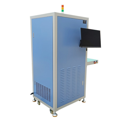
What is a Load Bank?
A load bank is a device designed to provide an artificial load to an electrical power source, such as a generator. This load mimics the operational or "real-world" load that the generator would encounter during actual use. Load banks can be categorized into three main types:
Resistive Load Banks: These simulate resistive loads, such as incandescent lighting and heating loads.
Reactive Load Banks: These simulate inductive loads, such as those found in motors and transformers.
Resistive/Reactive Load Banks: These provide a combination of both resistive and reactive loads to simulate more complex real-world conditions.
The Importance of Load Bank Testing
1. Verifying Generator Performance
Generators are often kept on standby for emergencies, which means they may not be used frequently. Regular load bank testing ensures that the generator is capable of handling its rated capacity when needed. This helps identify any performance issues that could lead to failures during actual operation.
2. Preventing Wet Stacking
Diesel generators, in particular, are prone to a condition known as wet stacking when operated at low loads for extended periods. Wet stacking occurs when unburned fuel accumulates in the exhaust system, leading to reduced efficiency and potential damage. Load bank testing helps prevent wet stacking by running the generator at higher loads, ensuring complete combustion of fuel.
3. Ensuring Proper Cooling
Generators are designed to operate at specific loads to maintain optimal cooling. Running a generator under low or no load can cause inadequate cooling, leading to overheating and potential damage. Load banks help maintain proper operating temperatures by applying appropriate loads during testing.
4. Identifying Potential Issues Early
Load bank testing can reveal hidden issues that might not be apparent during normal operation. These issues could include problems with the generator's electrical and mechanical systems, fuel system, or cooling system. Identifying and addressing these problems early can prevent costly repairs and downtime.
5. Compliance with Regulations
Many industries and jurisdictions have regulations that require regular load bank testing for backup generators. Compliance with these regulations is essential to ensure the safety and reliability of power systems. Using a load bank helps meet these regulatory requirements and avoid potential fines or penalties.
How Load Banks Work
Load banks simulate the load that a generator would encounter during actual use by converting electrical energy into heat. This process involves:
Connecting the Load Bank: The load bank is connected to the generator, typically through a series of power cables.
Applying the Load: The load bank applies a controlled load to the generator, which can be adjusted to simulate different load conditions.
Monitoring Performance: The generator's performance is monitored during the test, including parameters such as voltage, current, frequency, and temperature.
Analyzing Results: The data collected during the test is analyzed to identify any performance issues or potential areas for improvement.
The Role of EMAX Load Banks
At EMAX, we understand the critical importance of maintaining reliable generator performance. Our range of load banks is designed to meet the highest standards of quality and reliability, ensuring that your generators are always ready to perform when needed.
1. Advanced Testing Capabilities
EMAX load banks offer advanced testing capabilities, allowing for precise control and monitoring of load conditions. Our load banks are equipped with state-of-the-art instrumentation to provide accurate data on generator performance, helping you identify and address any issues quickly.
2. Versatility and Flexibility
EMAX load banks are designed to be versatile and flexible, capable of handling a wide range of load conditions. Whether you need resistive, reactive, or combined load testing, our load banks can meet your specific requirements.
3. Durability and Reliability
Built with robust materials and components, EMAX load banks are designed to withstand the rigors of regular testing. Our load banks are engineered for long-term reliability, ensuring that they can provide consistent performance over many years of use.
4. Ease of Use
EMAX load banks are user-friendly, with intuitive controls and interfaces that make testing straightforward and efficient. Our load banks are designed to be easy to set up and operate, allowing you to conduct tests quickly and accurately.
Conclusion
Load bank testing is a critical component of generator maintenance, ensuring that your generators are always ready to perform when needed. By providing controlled loads and precise monitoring, load banks help verify generator performance, prevent issues like wet stacking, and ensure compliance with regulations. EMAX load banks offer advanced testing capabilities, versatility, durability, and ease of use, making them the ideal choice for maintaining reliable power systems.
Investing in EMAX load banks is an investment in the reliability and efficiency of your generators. With EMAX, you can be confident that your generators will be ready to deliver power when it matters most. Contact us today to learn more about our range of load banks and how they can benefit your power systems.
3 notes
·
View notes
Text
12V DC Adapter: A Comprehensive Guide
Introduction
A 12V DC adapter is a common power supply unit used in various electronic devices, from routers and LED strips to security cameras and small appliances. It converts alternating current (AC) from a wall outlet into a stable 12-volt direct current (DC), ensuring safe and efficient operation. This guide explores its functions, types, applications, and how to choose the right one for your needs.
What Is a 12V DC Adapter?
A 12V DC adapter is an external power supply that provides 12 volts of direct current to electronic devices. It typically consists of:
A plug for the AC wall outlet
A transformer to step down voltage
A rectifier to convert AC to DC
A regulator to maintain a steady 12V output
These adapters come in different sizes, power ratings, and connector types to match various devices.
Types of 12V DC Adapters
Not all 12V DC adapters are the same. Key variations include:
1. Fixed vs. Adjustable Voltage
Fixed 12V adapters deliver a constant voltage, ideal for devices requiring stable power.
Adjustable adapters allow voltage adjustment (e.g., 3V-12V), useful for testing electronics.
2. Regulated vs. Unregulated
Regulated adapters maintain a steady 12V output even under load fluctuations.
Unregulated adapters may vary in voltage, suitable for simple, low-power devices.
3. Plug Types & Polarity
Connector types (barrel jack, USB, etc.) must match the device.
Polarity (center-positive or center-negative) must align to avoid damage.
Common Uses of a 12V DC Adapter
12V DC adapters power a wide range of devices, including:
Networking Equipment: Routers, modems, and switches.
LED Lighting: Strips, bulbs, and signage.
Security Systems: Cameras, monitors, and alarms.
Consumer Electronics: Radios, speakers, and portable TVs.
DIY Electronics: Arduino projects and small motors.
How to Choose the Right 12V DC Adapter
Selecting the correct 12V DC adapter involves checking:
1. Voltage & Current Rating
Must match the device’s requirements (e.g., 12V, 2A).
Higher amperage is acceptable, but voltage must be exact.
2. Connector Size & Polarity
Measure the device’s jack diameter (e.g., 5.5mm x 2.1mm).
Verify polarity markings (e.g., "+" on the inner pin).
3. Safety Certifications
Look for UL, CE, or RoHS compliance for reliability.
Troubleshooting a Faulty 12V DC Adapter
If your device isn’t working, check:
Loose connections (wiggle the plug).
Burnt smell or overheating (indicates internal failure).
Voltage output (use a multimeter to test).
If the adapter fails, replace it with a compatible model.
Conclusion
A 12V DC adapter is a versatile power solution for many electronics. Understanding its types, applications, and selection criteria ensures optimal performance and device safety. Always verify specifications before purchasing to avoid compatibility issues.

1 note
·
View note