#Aluminium pcb
Text
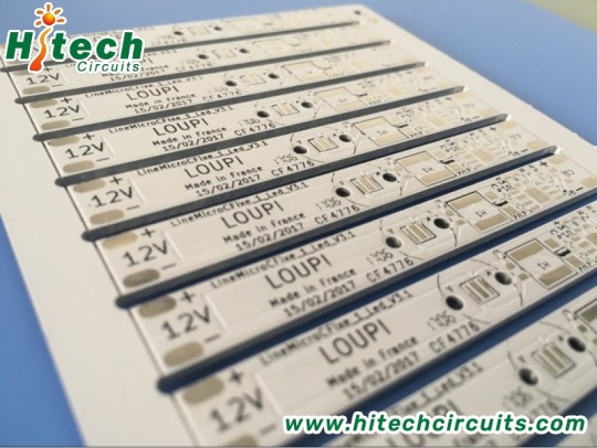

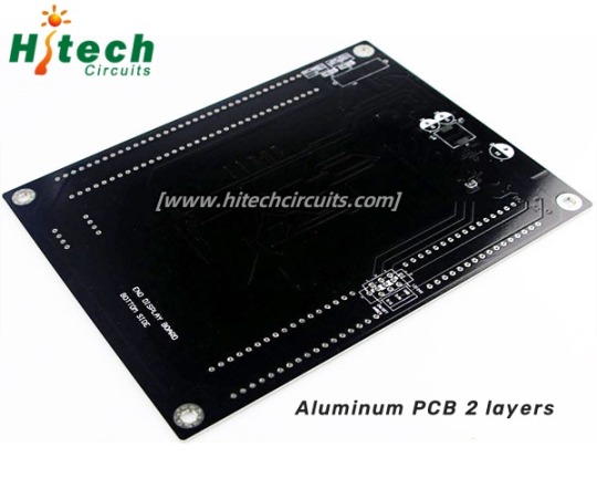
Aluminium PCB
Aluminium PCB are metal-based, copper-clad laminates with a good heat dissipation function. Usually, Aluminium PCB is refer to LED PCB board, which is the most important part of LED display and lighting products, etc.
Hitech Circuits Co., Limited is a professional aluminum pcb board, LED PCB manufacturer in China. Through 10 years of aluminum pcb board designing and manufacturing experience, Hitech are able to provide high quality and cost effective single layer, double layer and multi layer aluminum pcb boards to global customers. For any of your requirements regarding aluminum pcb board, please don’t hesitate to contact [email protected]
#Aluminium PCB#aluminum pcb#pcb assembly#pcb#engineering#technology#pcba#pcb manufacturer#pcbassembly#pcb design#hardware
5 notes
·
View notes
Text
One-stop PCB assembly service and PCB manufacturing supplier -- Hitechpcba
As a leading one-stop electronics manufacturing services provider in China, Hitech Circuits Co., Limited offers high quality, cost effective and quick turn PCB board products, Printed Circuit board, PCB assembly, electronics assembly manufacturing, Electronic parts components sourcing services for your new products development.
With mature supply chain, talented design team, advanced manufacturing techniques and quality control systems, Hitech Circuits Co., Limited is able to provide one-stop electronics manufacturing services and solution for our customers to help them stand out in the marketplace.
4 notes
·
View notes
Text
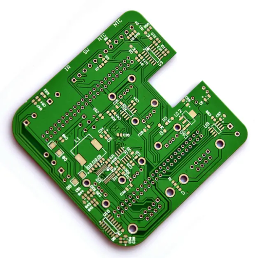
PCB Manufacturing

PCB manufacturing is a precision process involving designing, etching, and assembling printed circuit boards. We specialize in producing high-quality PCBs tailored to your specifications. Our advanced technology and rigorous quality control ensure reliability and performance. Trust us for efficient and cost-effective PCB manufacturing solutions to meet your electronic needs.
Visit Our Site: https://sqpcb.com/products/pcb-manufacture
#customized pcb boards#customize pcb#pcb board#pcb china#aluminium pcb board#multilayer pcb#printed circuit board#aluminum base pcb#circuit board#custom circuit boards
0 notes
Text
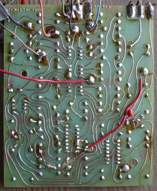
since I realise that there's probably a lot of people out there who never got to etch a circuit board in school, the basic principle of how a PCB or Printed Circuit Board is made is basically this:
You take a flat board, I believe usually fibreglass, that's been coated in a thin layer of conductive material, usually copper. You then mark out which bits of copper you want to keep versus the ones you don't, either physically or in software in some form depending on your method of etching, and then basically remove all the copper you don't want from the board, before finally coating the end result in what's called a solder mask to prevent solder from sticking to every single copper trace and risking short circuits - the solder mask being what makes the board actually green (or whatever other colour - there's a number of different possible ones!)
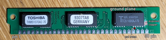
this also means that if you take a sharp hobby knife or the like and scrape away at the solder mask, you can expose or even cut the copper traces underneath, depending on whether you want to add or sever a connection somewhere.
Note that in this example (and in many other circuit boards) there's this very large and wide trace that covers most of the board where no other traces are present that I've labelled the ground plane - those are usually connected to either positive voltage or ground (in this case to ground via pins 9 and 22) and are used to provide easy access to either power or ground, plus their width means they can also pass much more current without overheating; in fact, if we were to compare this PCB to that of, say, a 100W+ something power supply...
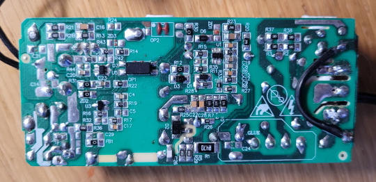
... you might notice the latter has some pretty beefy traces going around, especially towards the left and right ends of the PCB where the outputs and inputs respectively are located, due to the significant amounts of energy that might end up passing through those traces.
Meanwhile, most of the smaller traces and components are all primarily involved in regulating the behaviour of the larger and more powerful parts on the other side and therefore won't see all that much voltage or current. The big stuff is all topside and generally in contact with blocks of aluminium to act as heat sinks to prevent them from cooking themselves and releasing the magic smoke.
3 notes
·
View notes
Text
4 Crucial Things to Consider While Choosing LED PCB Manufacturer
LEDs have revolutionized lighting. At the heart of their brilliance, is the PCB assembly. Electing the right LED PCB assembly manufacturer can make or break your project. This ensures quality, performance, and ultimately, success. So, before you dive into the luminous world of LED PCBs, this article sheds some light on the key factors to consider when making your purchase:
1. Experience Matters: You should choose a manufacturer with proven expertise in LED PCB assembly. The company you choose should have a track record of successful projects similar to yours. Experience means they will understand your specific needs and deliver assemblies that meet or exceed your expectations.
2. Material Matters: The heart of your PCB is its materials. Go for manufacturers
who ensure high-quality FR4 or metal-core PCBs for optimal thermal management and longevity. They must adhere to industry standards for materials and components to guarantee reliability and safety.
3. Thermal Management: LEDs are designed to generate heat, so proper thermal management plays a crucial role. Look for manufacturers who offer solutions like aluminium heat sinks. Their expertise in thermal management can extend the lifespan of your LED PCB and prevent overheating issues.
4. Price is Not Everything: Though cost is important, its priority is not over quality.
The cheapest option might have hidden costs in the long run. Choose a manufacturer who offers budget-friendly pricing while maintaining high-quality standards and reliable service.
If you are looking for an LED PCB manufacturer near you you can count on Hitech Circuits Co., Limited. They have more than 20 years of experience in the electronics manufacturing industry. They have a talented design team who follow advanced manufacturing techniques.
These guidelines help you illuminate your path to finding the perfect LED PCB assembly manufacturer. Your choice has a direct impact on the performance, lifespan, and success of your project.
2 notes
·
View notes
Photo
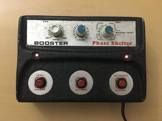
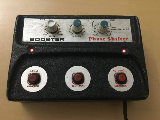
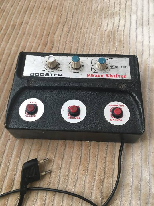
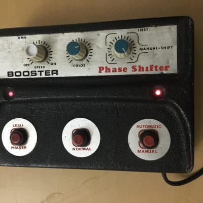
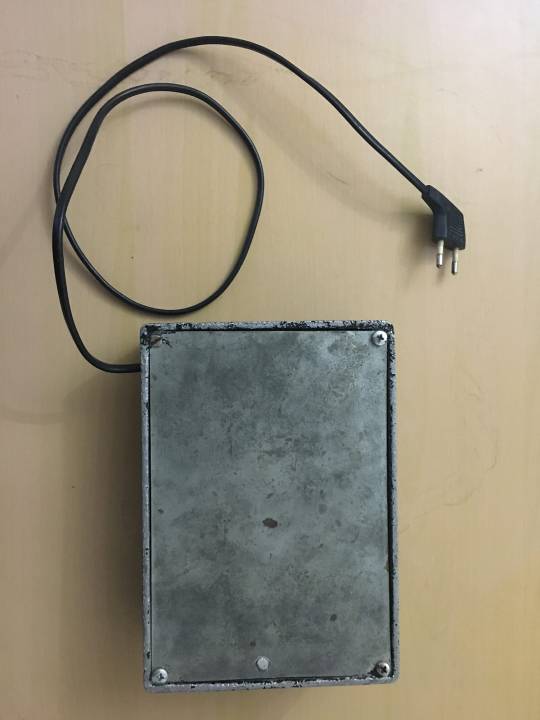
Booster - Phase Shifter
“70's made in Turkey ... 220v european voltage. ... Only very old people knows that brand "Booster" ”
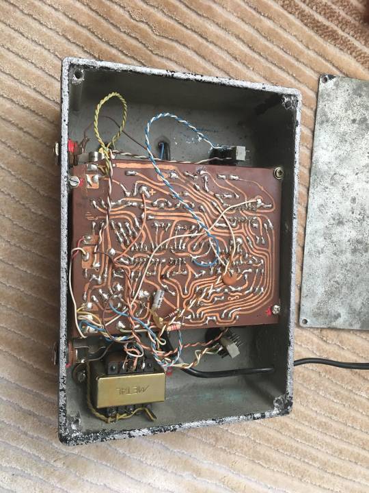
The rough sand-cast aluminium enclosure looks like a reference to early Roland-Boss enclosures, it does serve only little for knob-protection, though.
It has a quite low output, so “Booster” does not seem to be a function of the device, but maybe the brand name, indeed. Furthermore it offers a moderate phaser and sort of a flanger at the extreme settings of the speed knob.
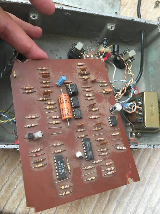
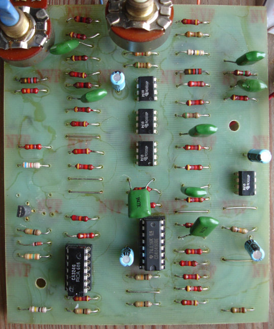
The PCB looks quite identical to an early Electro-Harmonics - Bad Stone phaser (the greenish, perhaps even older PCB is an example), so it might very well be a one-off rehouse with modifications.
Given it’s age there might be a connection to the Turkish Rock scene in the 70s?
Any hints welcome!
cred: reverb.com/Mustafa Sahin, home-wrecker.com/badstone.html
#made in Turkey#booster#phase shifter#phaser#spaghetti style#sandcast aluminium#anatolian rock#mislabeled#red footswitch
54 notes
·
View notes
Text
A metal desoldering pump is a handy tool that becomes very useful during PCB or circuit reworking. Simply heat the solder that you wish to remove and use the pump to suck in the molten solder for a clean de-soldering process. It allows you to remove components from PCB without overheating and damaging the pads.
Soldering is one of the most basic skills required to be an Electrical and electronics engineer. You need to solder different components on the PCB, solder on the joints, etc to make reliable and sturdy electrical connections for its intended working. But sometimes things can go wrong and you might end up making a wrong connection or there is excess amounts of solder on a connection that you need to remove then there is a problem! You can not take out that solder unless you are a highly skilled soldering person. To solve this problem you can use this Tin suction gun which you can use to suck out the extra tin solder you have put on the PCB or to remove that connection. It has an aluminium suction tip that provides you the sturdiness and longevity to get it to work for a long time.
2 notes
·
View notes
Text
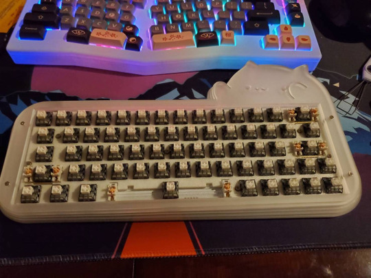
epomaker mini cat 64 build talk
ok i guess a couple people said theyd be interested so let's talk to most recent custom i did, for my friend @jowritesfantasy, of an epomaker mini cat 64.

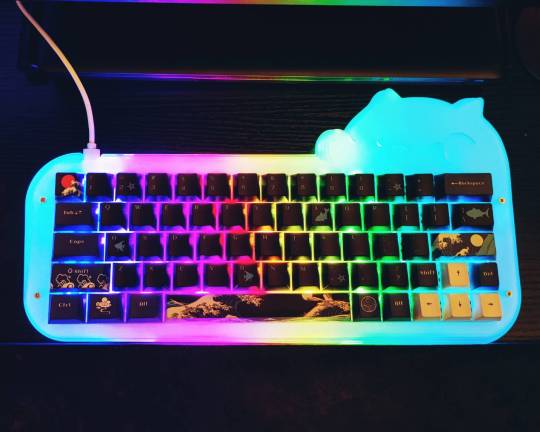
the final build is an epomaker mini cat 64, with kailh box white v2 switches, and a great wave off of kanagawa (dark) cherry profile keycap set. total cost for what is essentially a full (budget) custom build is about $150USD without tax (off of bezoshell).
note: i am a vision-impaired hobbyist with shitty, shaky hands. i am by far not an expert. this is literally just "all the crap i've had to figure out from the ground up as a basic guide". there are more comprehensive references out there, and build guide videos for most custom kits, and do more research, not less, before building. nothing here is gospel and many people do it differently.
anyway, let's talk turkey.
BASIC GLOSSARY:
keyboard: the whole shebang. case, pcb, switch, caps, everything. the thing you type on.
case: the acrylic/aluminium/ceramic/whatever body that the pcb, switches, and keys live in.
pcb: the brain of the keyboard. you can have one where the switches must be soldered in, or you can have one where the switches can be hot swapped, which means you can change them out without any need to use a soldering iron. pcbs can be bought separately from cases.
group buy: when a bunch of people buy in to get a custom keyboard made by pooling resources up front.
switch: the mechanical switch that you solder or hot swap into a pcb to make the button press. there are thre (standard) types: linear, tactile, and clicky. switches work just fine without lubing. this is optional.
stabilizers/stabs: the support stabilizers for your wider keys that help keep them steady and don't let them wobble. there are two standard types—pcb mounted (screw-in, usually) and plate-mounted (click-in). please lube your stabs. krytox 205g0 is good. otherwise trust me, they will rattle. oh, god, will they fucking rattle.
keycaps: the thingy that goes on top of the switch that you actually press. they come in about a million profiles and in every possible permutation or color you can think of. if they're cherry/mx stem, they'll be compatible with most modern mechanical keyboard switches on the market.
QMK/VIA: software that lets you change what buttons on your keyboard do what.
keyboard %/keyboard #: how many keys are on the keyboard. the 64 mini cat has...64 keys. a 78ish key is the full f-row and most standard laptop keyboards. TKL is tenkeyless, or no numpad. 100%/180 is the entire keyboard, numpad and all. 40% is babymode aka "you like layers? i'll give you layers". each board has its use, everyone has their preferences.
ergo: a keyboard designed to be more ergonomic. ergo boards have different layouts and spacing and height. some are split, some aren't, these days one of the more standard ergo layouts is the alice/arisu. it's nice. i recommend it. (my custom is an alice)
custom: you build it, you decide everything you want on it, you buy all that shit, and you put it together.
prebuilt: open box, plug and play.
from the getgo, while epomaker does offer this for sale ready to plug and play, i knew we would not be buying this premade (both because i wanted to build it, the whole point was i wanted to build it and jo wanted it) and also, epomaker didn't offer clicky switches. jo's previous board had cherry/gateron (not clear which? one or the other) blues, which are the "standard" clicky switch: they're 65g actuation, they click, and there are better options. (note: this blog is a cherry mx hatezone. sorry.) i also knew that i was going to have to get a bit creative with VIA layers because jo works on spreadsheets and this is a 64 key board—no numpad. you kinda need a numpad for spreadsheets.
i didn't know much about clicky keys before this (i personally have sad shitty little goobaby hands that can barely even handle 43g linear switches and most people i know use tactiles), so i had to do a bit of research. you can hear (cherry only) sound profiles and comparison here, and this gives you a pretty standard idea of what mechanical switches sound like.
linear keys tend to be the lightest actuation, since they're for gaming most of the time; tactiles are all over the place and have the most options since theyre the most popular; clicky tend to be a little heavier overall. the "actuation" force in grams is how much pressure it takes to make a keypress go through, the "bottom out" is how much it takes to make the key hit the bottom of its arc. tactiles and clicky keys both make sounds/have texture bumps when the actuation of the key happens; linears you just push.
a short list selection:
cherry mx blue (the "standard" click): 60g actuation, 60g bottom out.
gateron blues (the original clone of the standard): 55g actuation.
cherry mx green/gateron green: 80g actuation, 90g bottom out
kailh box white v2: 45g actuation, 55g bottom out. (note: this is the same actuation/bottom out as the v1; the v2 has increased stability and stronger springs)
we ended up picking the kailh box white v2s because of comparative sound testing, the revision being even sturdier than the original box whites, they were on sale when we bought them and came in a closer to 64 switch pack, and they're about 65¢ a switch. not bad, all things considered. they're lighter than the standard mx blue, have a brighter, springier sound (even unlubed) and the "box" around the stem of the switch makes the connection between switch and keycap more reliable, which is a problem that happened to jo's old keyboard (the stem housing of the keycap broke; there's basically no way to get a replacement without shelling out a good bit of cash for an entire set, the box should help prevent that in the future).
the next thing was keycaps—you can do research about keycap profiles until the cows come home, but there's basically two types. "flat" keycaps are interchangeable per row (so work great if you aren't using a qwerty layout or you don't have a standard layout keyboard), "differentiated" have different heights per row (so work great if you have a hard time finding the right keys or are using a condensed keyboard model where you might get lost in the sauce if everything is the same).
the most common profile is cherry—if you want to find something super fun keycaps-wise, cherry is probably what you'll end up with. every keycap profile presents a slightly different sound because of how the plastic housing handles the noise of the switch (sa has more hollow thock; xda has a little more rumble because it's flat; cherry is a little snappier). frankly, imo, the texture/shape of the key is more the question to keep in mind (as well as the type of plastic they're made with—pbt is much, much more reliable). jo wanted dark wave with whale, we found dark wave with whale, it was cherry profile. success.
(note: knockoff keycaps can be a mixed bag—they use different fonts, the stems can be less reliable, even if they are doubleshot (two different kinds of plastic, layered on top of each other for more stability) and pbt. however, they're a lot more affordable. i like having more keycaps. im also cheap. that said, groupbuy or direct from source keycaps are also rad as hell. it's your call)
the epomaker mini cat is a hot-swap board, which means all that the switches had to do was to be popped into their housing. when popping switches into hotswap, always test the pcb beforehand. always. if you fuck up the pcb during switch installation, that is what it is, and you want to know if there's a problem before that happens. (shit can get weird. trust me. my custom pcb is currently getting replaced because of a freak usb-c daughterboard soldering incident that basically cannot be fixed, and everything worked fine in testing... but it's uncommon).
to build this board, i took it in a series of steps:
1: disassemble the entire board, flip the pcb (the "brain" of the keyboard) over, and manually test all the keys with a keyboard tester website and a paperclip. to test the diodes, you want to put your paperclip/tweezers/whatever into the outsides of the diode, not directly into the slot where your switch pins will go

you shouldn't need to shove. just set them there. your key tester should click, light up, or, if you're me, say "josh"
2: once i knew the pcb was good, it was time to disassembe the plate and the stabs. the stabs that came with the mini-cat 64 were plate-mounted and came unlubed, so i clicked them out with my tiny screwdriver, took them apart, and lubed them. if i had a buck for every stabilizer build and lube guide that actually refused to show the parts of a stabilizer, i'd have a lot of bucks, so here's some photos from me. these are akko transparent pink pcb-mounted, screw-in stabilizers. my hands are shaky as fuck so i apologize for any blurriness.

there are three basic components to the stabilizer—the bar, and the two-part housing. when you take a stabilizer apart, whether or not it's screw-in or clip-in, the bar clips and unclips, and the housing works the same.
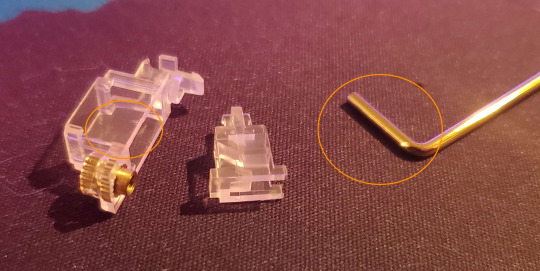
less lube is always better (you can always add more): when lubing stabs, you want to lube the inside of the larger housing on the two wider portions and the back, where the smaller portion is levered up and down and will hit the plastic, and the part of the bar that goes into it. this is all the stuff that will click and clack if it touches each other.
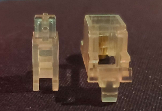
sorry this is a transparent stab so it's kind of hard to see, but when reassembling your stabilizers, the smaller piece will have one side with two holes, and one side with one hole. two holes goes in the front. business in the front, party in the back, whatever. you can see here where the clicky space thing that you click the stabilizer bar into.

i apologize for my shaky ass hands. sorry. the realy nice thing about transparent stabs, otoh, is you can see where the actual bar goes—it goes into the bottom of the two holes, so that the interior part of the housing is lifted up and down when the bar moves. that's it! click it in once it's in the right hole, you're done.
3: it is time to Insert the Switch. most switches tend to be plate-mounted. the "plate" is the part of the case that goes above the pcb, and is what aligns (and holds in) the switches, so that they land in the right spot. here's an example of a pcb and a plate

the plate fits on over the stabs, and then you have your "alignment" for your switches in place. now you know where your switches go, it's time to stick them in. the smaller, metal holes on each switch location are where the pins go—this is a "south facing" rgb pcb, meaning the pins go in up top, with the smd led (the little per-switch light) facing toward, not away from, the user. north-facing switches are more common. (for anyone curious, this is a mechloving adelais en ciel rv3 pcb, akko transparent pink screw-in stabs, and a switchcouture aluminium plate)
take your switch, align your pins, push in the side with the pins first to be sure they go into their sockets straight, and then push them the rest of the way in to click. hot swap sockets can be finnicky and a little fragile, so when installing switches into a hot swap pcb, you want to push straight down into something below—i.e., take the back off of the case and put the pcb flat on a soft, but sturdy, surface, like a deskmat. then click them in.
and now you've got a keyboard! time for the fun part. put those keycaps on and give it a test.
well, now you have a working keyboard. except for one small issue... the person using this keyboard needs a numpad! okay, so that means that you need to get CREATIVE.
all our keyboards have some level of "layer mapping"—shift + a = A. that's a layer, becuse it changes the key input. on my keyboard, because i use a mac with the extended international keyboard, alt + a = ¯. that's another layer. most people are more familiar with fn + 1 = f1. that's a layer.
for this keyboard, since jo needed a numpad, the way to do that is to make use of it being via compatible and to build that in as a layer. via is a great program (wish it worked with firefox!) in that it's as close to plug and play as you can really get for something like this. it's all overlay, you just click what you need. i am stupidbad at tech, and i can figure it out. let's take a look at the layers that are mapped into this keyboard:


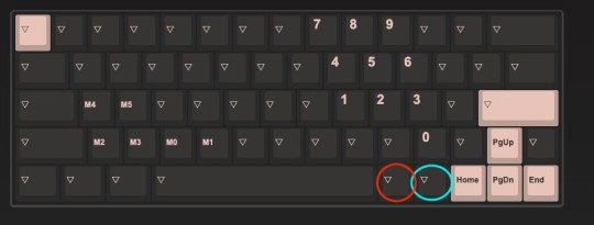
here we have layer 0 (the "home" layer, what the keyboard's base state is), layer 1 (the "modifier" layer), and layer 2 (the "spreadsheet") layer. i made a few changes after i took these screenshots pgup/dwn/home/end are on the modifier layer now and not just the spreadhseet layer), but this is pretty much the final version. in via, the upside-down triangle means that the button naturally defers down to the layer below it. this means, on all layers, the red circle is always the fn/modifier button. if you're on the spreadsheet layer and press fn+1, it will be f1, because that button is always fn.
the "modifier" layer came baked into the keyboard, since that's the way that the function row buttons/the keyboard light adjustment works. all i added was the blue "toggle" layer button, which, when pressed with the fn button, turns the spreadsheet layer on.
even more simply, if you push fn+ralt, it makes the keyboard be for spreadsheets.
on the spreadsheet layer, the right-hand side of the keyboard becomes a numpad, the arrows automatically work as up/down/home/end, and, most importantly, a/s/z/x/c/v are all macros. what those look like, in the via programming, is {KC_LCTL,KC_C} (that's "ctrl+c" as one button press), with the KC_[] changed out for the key you're swapping in as a shortcut. when on the spreadsheet layer, pressing "z" is the same as "ctrl/cmd+z" normally is—only now you only have to hit the button once. that's true for that entire set of macros. so, if you need to save? hit s. if you need to select all? hit a. if you need to cut? hit x. paste? hit v. there's no need to push ctrl at the same time—that's baked into the keys.
you can do this with any keyboard that is qmk/via compatible, by the way. it's fucking amazing. if you work on spreadsheets all the time? awesome. now you can numberpunch one-handed, and copy/paste/undo with the other, no need to use multiple keys.
the macro building and layering on via for this keyboard was waaaay better than what i did on my wife 1.0 (sorry, wife 1.0) and i'll be using the same setup on wife 2.0 (whenver wife 2.0 gets here). overall, this is honestly a really affordable custom board with a lot of adjustment options built in. it was a ton of fun to build, really simple and straightforward in terms of setup, and it's got bongocat on it.
also honestly if i had to get clickies, i'd do the box whites. they're really nice and dont make my fingers feel like they're about to break when typing.
#keycaps are for eating#next time whenever wife 2.0 comes in the mail i'll talk about all-custom builds i guess and more advanced via stuff#and keycap changing in and out#and what kind of screwdrivers you want#uh. and also aviator cables maybe i guess.
18 notes
·
View notes
Text
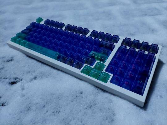
Leopold FC980m
Custom PCB (source)
Aflion Melody and Runner switches
Deadline Studio AirR PC keycaps
Lightblue painted stock aluminium plate
Stock plate-mounted clip-in stabilizers
More under the cut.

This build took well over a year to actually get it to it's current state and it's technically not done yet, considering I still have to tune and lube the stock stabilizers.
Issue number 1 before everything else was getting the cherry mx brown switches out of the old PCB to be able to remove the plate because I didn't want to order a custom plate or go plateless. The solder used on the original PCB has a stupid melting point so not only did I have to dilute the solder with my own that melts at roughly 320°c, but my soldering iron was set to 410°c (or more for specific spots, more on that later). A good chunk of the extracted switches were simply not usable anymore afterwards from being slightly molten. The plate has a few hooks and the PCB has holes for them to hook into, one of which is a PTH (plated through hole) hole that goes to the PCB's ground and the corresponding hook lacks paint and is soldered into this hole. This cursed and damned hook was the reason for a lot of frustration as it took quite literally half an hour (maybe more) to de-solder at 435°c while constantly adding and removing solder to slowly chip away at this literal mountain of solder they used.
My next problem was simply getting the new PCB(s). Back then I was a bit tight on money from expenses out of my other hobbies and various mundane things I needed, so it took a month or two to be able to finally order them. Except JLCPCB, the service that was recommended for this PCB by this keebtalk thread, ran out of the MCUs I needed, so I researched if they had any alternatives, but by the time I read enough of the documentation of various alternatives and found one, that one ended up being out of stock as well. So another couple of months passed basically just waiting.
After ordering, an engineer of JLCPCB contacted me because some of the NPTH (non-plated through hole) holes were too close to each other and would be at risk of breaking while drilling and the best option seemed to be just making them PTH holes, because the hook holes aren't connected to anything and the plate's paint makes it non-conductive anyways so it should be fine. Right?
FORESHADOWING IS A LITERARY DEVI-
I eventually get the new PCBs and of course immediately scratch one of the 5 I ordered (it still works), tested 2 of them and went to work.
Across a couple months (I was preoccupied, blah blah lazy excuses) I slowly chipped away at soldering in the MillMax sockets.
Couldn't have 4 minutes without problems though, now can we?
Trying to install the switches and PCB didn't work because the MillMax sockets add roughly a millimeter of distance between PCB and plate and you can already guess that this doesn't play nice with the plate's hooks. I trimmed off the hooks but left them as little poles for aligning the PCB and so everything would be alright. Right?

I assemble the keyboard fully and plug it in to see... it not working.
I assumed due to the extra millimeter from the hotswap sockets messing with the tolerances, there may be a short to the daughter board, so I took it apart again and taped any contacts and it still didn't work after reassembly. Now I was getting quite annoyed so I took off the top of the casing and tested it like that and surprisingly it worked. Kinda.
As soon as I snapped the top of the case back on, or pressed down on the plate in the bottom left corner, the keyboard would fire A bunch of keys at the same time.
Seeing this set of keys led me to the right path. I double checked this side of the PCB and saw that the hole for the PCB hook next to caps was PTH rather than NPTH and connected to one of the contacts for caps. Remember when I said one of the hooks was connected straight to ground? Or how I had to remove part of the plate hooks, thus removing the paint that prevents it from conducting electricity? Yeah. One strip of tape later and everything is fixed and works perfectly fine.
That's basically it. It was a pain, but it looks, sounds and types nicely.
I'm happy with how it turned out.
2 notes
·
View notes
Text
okay friends!
if anyone was curious about what i decided for the keycaps from my poll results...
i decided to go with these keychrons, they are still cherry profile, but they are closer to the black and cyan akko keycaps in terms of color scheme. i went with these bc they are in stock and slightly cheaper than the akko's. while i do like the ASA profile of the akko's, i am spending a lot of money on this keyboard and anywhere i can save a little money helps. and after buying all of this... i need to STOP spending money 😂
so i have ordered everything i need for my new, fully customized mechanical keyboard! the keycaps, switches (silent switches!), and o-rings (a new addition) should be arriving at the beginning of next week. my keychron Q1 pro pcb should arrive in 4-6 business days after it ships.
to say i'm excited is an understatement. i do have a little experience with pulling keycaps and replacing switches, but i have never fully built a keyboard. i'm not sure if i'll do any other modifications to the pcb, like a tape mod. i guess i'll put it all together and see what i think about the sound. i might like the "ping" from the aluminium case.
my new desk is also assembled. i was going to hold off putting it together, but yesterday was kind of stressful and i wanted to take my mind off work so i built my desk. i am so happy with all the storage space i now have! i'll be moving my desk into my room tomorrow. we're going to clean the house, so my rugs will be nice and clean before placing the new desk!
i know most of you don't really care about this but i am just really excited 😂 i hope you're having a good week/weekend, please stay safe out there, and stay hydrated my friends! 💖
2 notes
·
View notes
Text
Innovatives Design, grenzenlose Innovation - Hitech Circuits Aluminium-Leiterplatten!
Auf der Suche nach einem zuverlässigen Lieferanten für Aluminium-Leiterplatten? Suchen Sie nicht weiter! Hitech Circuits ist branchenführend und bietet Ihnen die hochwertigsten und zuverlässigsten Lösungen für Aluminium-Leiterplatten.
Als führender Hersteller von Leiterplatten setzt Hitech Circuits auf Innovation und bemüht sich, seinen Kunden hochleistungsfähige und hochwertige Produkte anzubieten. Unsere Aluminium-Leiterplatten zeichnen sich nicht nur durch hervorragende Wärmeableitung aus, sondern bieten auch eine ausgezeichnete Haltbarkeit und Stabilität, um den Anforderungen verschiedenster anspruchsvoller Anwendungsumgebungen gerecht zu werden.
Die Aluminium-Leiterplatten von Hitech Circuits werden mit fortschrittlichen Fertigungstechnologien und hochwertigen Rohstoffen hergestellt, um sicherzustellen, dass jede Leiterplatte eine gleichbleibend hohe Qualität aufweist. Unser erfahrenes Team fertigt die Aluminium-Leiterplatten gemäß Ihren Anforderungen und Spezifikationen an, um sicherzustellen, dass sie perfekt zu Ihrem Projekt passen.
Mit den Aluminium-Leiterplatten von Hitech Circuits erhalten Sie:
Hervorragende Wärmeableitung: Unsere Aluminium-Leiterplatten sind so konzipiert, dass sie effektiv Wärme ableiten und eine kontinuierliche, stabile Funktion Ihrer elektronischen Geräte gewährleisten.
Zuverlässige Qualitätsgarantie: Wir halten uns strikt an internationale Standards und verwenden hochwertige Rohstoffe sowie fortschrittliche Fertigungstechnologien, um die gleichbleibende Qualität unserer Produkte sicherzustellen.
Maßgeschneiderte Lösungen: Wir bieten maßgeschneiderte Lösungen für Aluminium-Leiterplatten, die Ihren spezifischen Projektanforderungen entsprechen und Ihnen die bestmögliche Lösung bieten.
Professionelle technische Unterstützung: Unser erfahrenes technisches Team steht Ihnen jederzeit zur Verfügung, um Ihnen technische Unterstützung und Beratung zu bieten und sicherzustellen, dass Ihr Projekt reibungslos verläuft.
Wählen Sie noch heute die Aluminium-Leiterplatten von Hitech Circuits und bringen Sie frischen Wind in Ihr Projekt! Kontaktieren Sie unser Team, um mehr über unsere Produkte und Dienstleistungen zu erfahren.
1 note
·
View note
Text

Multilayer PCBs offer enhanced functionality by incorporating multiple circuit layers into a single board. These versatile boards enable complex electronic designs, compact layouts, and signal integrity. Our multilayer PCBs are meticulously manufactured, meeting industry standards for various applications, including consumer electronics, telecommunications, and aerospace technology.
Visit: https://sqpcb.com/products_category/multilayer-pcb
#Multilayer PCB#customized pcb boards#customize pcb#pcb board#aluminium pcb board#pcb china#printed circuit board#aluminum base pcb#circuit board#custom circuit boards
0 notes
Text
Mechanical keyboard craze
You guys probably have heard about keyboard, no not the one that produces music, but the one that you use to type on your computer screen, and do you know that there are a group of people that willing to spend and take their time to buy, build, and customize their own keyboard up to their liking. Let me introduce you to the world of custom mechanical keyboard, you probably heard the word mechanical keyboard and its usually relates to those gamer and very loud and clicky keyboard.
This niche hobby started and documented on Geekhack.com, a place where people with keyboards and similar interest on keyboard gather and discuss and continue to grow bigger and bigger until today with lots of layout, colorful keycaps and keyboard with various age and variants, availability and many different custom mechanical keyboard forum appear in the wild such as Reddit thread, Facebook groups and Discord Communities.
This niche hobby of building a keyboard took a blast back when Nathan “ Taeha-types” Kim built a keyboard for a professional Fortnite player name Tfue, that cost a whopping 3500 USD which translates roughly to around 55 Million IDR today and gather around 8 Million views on his youtube channel, and after that video released, COVID-19 happens and all people were forced to work from home, and people still doesn’t know when will this pandemic going to end, so many people decide to revamp their work setup to make it as comfortable as they want, and some of them were fallen into this niche hobby and one of the discussion forum on reddit that commonly known as r/mk or r/Mechanical Keyboards, as for today the forum got 1.1 Million members with top 1% ranking on the entire reddit community.
After the whole brief history of the hobby, let’s get into what you need and how to make a custom keyboard for yourself. There are 6 main components that were required to make a keyboard.
Case: It’s the shell to keep your keyboard together, you usually come by a case that were made out of wood, plastic and aluminium,
Printed Circuit Board or PCB: This is the heart of the keyboards, where you put all your components together, the feature on a keyboards were determine by the PCB you use, maybe your PCB supports Bluetooth connectivity or your PCB got the RGB lighting and other stuff.
Plate: a plate functions as an alignment tool so your switches sit straight right on top of your PCB, plate material can be found in a plastic, brass, carbon fibre, and aluminium.
Switches: this is the part that makes every keys you press register a keystroke, switches comes in many colour and many flavours, the most commonly seen were Blue for clicky and tactile feeling on your switches, Red for linear type of switches without any feedback on the feel, and Browns for the soft tactile feedback every time you press on the switches.
Stabilizers or “stabs”: Stabs were used to help support the longer keys such as spacebar, enter, backspace and shift, this comes in various different sizes such as 2u that commonly used on shift, enter and backspace, and there is 7u and 6.25u that used on the spacebar.
Keycaps: the keys with letters and symbols on it with different colours and different shapes.
You might be wondering, why do I need to go through this many process just to build a keyboard, meanwhile I can buy a Logitech keyboard of from computer store for less money. Building or buying a custom keyboard really is a big game changer, you can choose the size of the keyboard, if you need numpad and function rows, you can go with something bigger, but if you don’t need those, you can go with something with a small form factor, or do you have a specific typing method, you can go with something more ergonomic, are you a loud typist or a silent typist, do you want it to be very heavy or portable, you can customize everything from the outside to the inside of the keyboard and from the sound to the feel of the keyboard.
2 notes
·
View notes
Text
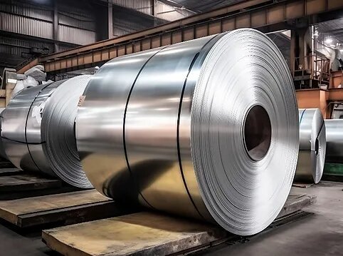
Aluminium Coil Manufacturers
Printed Circuit Board Entry
Marudhar’s Printed Circuit Board (PCB) entry sheets are manufactured with state-of-the-art equipment which matches international standards. Tight thickness tolerance, flatness, dimensional accuracy, grease-free surface and hardness optimal for burr-free drilling required in the manufacture of PCB are ensured. Marudhar Industries is one of the leading Aluminium Coil Manufacturer, supplier, and exporters in india. We Provoide High Quality Aluminium Coil at best price.
Continuous upgrades and process improvement enable us to keep pace with the demands of its ever-growing clientele.
Aluminum PCB (Printed Circuit Board) Entry Sheets
Specifications:
Marudhar’s Printed Circuit Board (PCB) entry sheets are manufactured with state-of-the-art equipment which matches international standards. Tight thickness tolerance, flatness, dimensional accuracy and grease-free surface and hardness optimal for burr-free drilling required in the manufacture of PCB are ensured.
Continuous upgrades and process improvement enable us to keep pace with the demands of its ever-growing clientele.
Application Standards:
ASTM-B-209M, Aluminium association — aluminium standards and data, Marudhar manufacturing limits (as applicable).
Packing:
The PCB entry sheets are wrapped with HDPE, hardboard on top and bottom of the stack, hoop iron along the length of the sheets and is placed on wooden skids with runners and finally put in wooden boxes. Silica gel packets for moisture protection are used.
Applications:
Electronic circuit boards
Foil Stock
Marudhar’s foil stock is produced from high-quality rolling ingots and concast coils. Manufactured with sophisticated equipment, the foil stock is free of surface and subsurface defects. Matching international quality standards, it can be rolled to thin gauges of aluminium foil for a number of applications.
Foil Stock
Specifications:
Marudhar’s foil stock is produced from high-quality rolling ingots and concast coils. Manufactured with sophisticated equipment, the foil stock is free of surface and subsurface defects. Matching international quality standards, it can be rolled to thin gauges of aluminium foil for a number of applications.
Stringent quality checks ensure a world-class range of sheets, extrusions and foil products from Marudhar. Continuous upgrades and process improvement enable it to keep pace with the demands of its ever-growing markets.
Flatness:
Less than 20 I units (typical)
Wedge:
Within 0.7% (typical)
Coil Build-up Quality:
Weave — 2 mm (max), total shift 5 mm (max)
Surface Quality:
Suitable for foil rolling
Application Standards:
ASTM — B -209M, Aluminium association — aluminium standards and data, Marudhar manufacturing limits (as applicable).
Packing:
Foil stock is wrapped in HDPE fabric and hardboard, strapped with hoop iron and placed in an eye-to-sky or eye-to-wall position. Moisture protection is provided with silica gel packets.
Applications:
Pharma / Confectioneries / Cigarette Foils
Foils
Tetra packs
Closure Stock (PP Caps)
Marudhar’s closure stock is rolled to very fine tolerances to yield more closure per ton of stock and to allow uninterrupted operation of high-speed, multiple-cavity presses. Its strength, high formability, low earring and printable surfaces make it ideal for pilfer-proof caps and vial seals.
PP Cap Sheets (Closure Stock)
Specifications:
Marudhar’s closure stock is rolled to very fine tolerances to yield more closure per ton of stock and to allow uninterrupted operation of high-speed, multiple-cavity presses. Its strength, high formability, low earring and printable surfaces make it ideal for pilfer-proof caps and vial seals.
Packing:
Sheet: Sheets are placed in wooden boxes on wooden skids with runners along the length of the sheet. They are wrapped in HDPE with hardboard on top and bottom of the stack. Hoop iron strapping runs along the length of the sheets. Silica gel packets are put in the boxes for moisture protection.
Alternatively, they are wrapped in a poly-laminated gunny or polythene, strapped with a hoop iron strap and clip and placed on a wooden pallet. Edge guards are used and the sheets are wrapped with protective thermocol sheets.
Coil: Coil is placed on wooden pallets in either eye-to-sky or eye-to-wall condition, wrapped in HDPE fabric and hardboard, and strapped with hoop iron. Silica gel packets are used for moisture protection.
Applications:
Pilfer-Proof Caps
Vial Seals
Cream Containers & Caps
Fin Stock (HVAC)
By meeting the stringent specifications of globally competitive companies, Marudhar’s flat fin stock has proved its worth in air conditioners, car radiators and heat exchangers. With the help of high-quality ingots, state-of-the-art gauge ,shape control and precision slitting. We manufacture fin stock that has tight gauge tolerances and excellent slit edges. A tight build-up combined with internal sound metallurgical properties produce good drawability required for all types of finning.
Fin Stock [HVAC Foils]
Specifications:
By meeting stringent specifications of globally competitive companies, Marudhar’s flat fin stock has proved its worth in air conditioners, car radiators and heat exchangers. With the help of high-quality ingots, state-of-the-art gauge and shape control and precision slitting, we manufacture fin stock that has tight gauge tolerances and excellent slit edges. A tight build-up combined with internal sound metallurgical properties produce good draw ability required for all types of finning;
Packing:
Marudhar’s flat fin stock is packed on wooden skids in either eye-to-sky or eye-to-wall condition, wrapped in HDPE fabric and hardboard and strapped with hoop iron. Moisture protection is ensured with silica gel packets and as the final step, the entire packed product is placed in a wooden cage.
Applications:
Air Conditioners
Car Radiators
Automobile Heat Exchangers
Tread Plated
Marudhar’s pattern sheets are ideal for decorative applications and interior panelling for trucks, cabins, etc. Available in five designs — diamond, five-bar, two-bar, propeller, and north star — the sheets can be bent easily or curved to take the shape of the structure in which they are fixed. Pattern sheets are light, rust-free, hygienic and easy to clean, and because they are made from aluminium, they are resistant to corrosion and denting.
The sheets are manufactured with state-of-the-art equipment employing sophisticated process technology. With stringent quality control measures in place, the company sets the standard in aluminium panelling.
Pattern Sheets/Coils (Chequered/Tread Plates)
Specifications:
Marudhar’s pattern sheets are ideal for decorative applications and interior panelling for trucks, cabins, etc.
Available in five designs — diamond, five-bar, two-bar, propeller, north star — the sheets can be bent easily or curved to take the shape of the structure in which they are fixed. Pattern sheets are light, rust-free, hygienic and easy-to-clean and because they are made from aluminium, they are resistant to corrosion and denting.
The sheets are manufactured with state-of-the-art equipment employing sophisticated process technology. With stringent quality control measures in place, the company sets the standard in aluminium panelling.
Packing:
Marudhar’s pattern sheets are packed with a poly-laminated gunny, hardboard, strapped with hoop iron and clip, and placed on a pallet.
Applications:
Decorative applications like interior panelling for trucks, cabins, etc.
Cast Coil
Marudhar’s cold rolled coils/sheets are precision-finished to match international standards. They have good shape, high tolerance, versatility and blemish-free surfaces. They are used in commercial and general engineering applications such as bus bodies, cladding and fan blades. The company meets the demands of its ever-growing clientele with continuous upgrades and process improvement.
Aluminium Alloy Cast Coil
Specifications:
Our cast coils are used to produce superior-quality Insulation Cladding, Flooring Sheets, Roof Sheets, Nets, Balls Chain, Circles, Chequered Sheets, Cold Rollind, Utensils Making and many more products.Aluminium and its alloy cast coils are of a smooth surface, have no burr and are of high quality in terms of flatness and surface roughness.
According to the analysis, the chemical composition, homogenizing, shearing, intrinsic properties organization, hardness and other mechanical properties of materials will affect the application. In common the cast coils come with the tempers range as O. The thickness is 6–8mm and the width is 762–1250mm.
Product Name Aluminium Alloys Cast Coil Grades 1070, 1060, 1050, 1100, 1200, 1235, 3003, 3004, 3105, 8011, 8079, GEQ Temper O Specification Thickness: 6–8mm Width: 762–1250mm Quantity tolerance ±10% ID 200, 305, 405 and 505mm Surface treatment Mill finish Application Insulation Cladding, Flooring Sheets, Roof Sheets, Nets, Balls Chain, Circles, Chequered Sheets, Cold Rolling, Utensils Making and many more products Packaging Wooden Pallet Remark Aluminium Alloys Cast Coils can be customized
Application:
Insulation Cladding, Flooring Sheets, Roof Sheets, Nets, Balls Chain, Circles, Chequered Sheets, Cold Rolling, Utensils Making and many more products.
Slit quality:
Free from nicks, cuts and burrs.
Coil build-up:
Uniform and tight enough to be handled horizontally.
Applicable standards:
ASTM — SB -209M, Aluminium association — aluminium standards and data, Marudhar manufacturing limits (as applicable).
Packing:
Aluminium Alloys Cast Coils are placed on wooden skids in an eye-to-wall position. It is wrapped in HDPE fabric and hardboard and strapped with hoop iron. Moisture protection is ensured with silica gel packets and the entire packed product is placed in a wooden box.
Cable Armouring Strips
Marudhar meets global standards in the manufacture of its cable wrap stock, which is widely used in various cable brands.
With the help of high-quality ingots and state-of-the-art control systems, Marudhar manufactures cable wrap stock with tighter gauge tolerances and meets excellent elongation and length requirements.
Cable Armouring Strips Stock (Cable Armoring Coils)
Specifications:
Our aluminium cable armouring strip stock is used as a conductor to wound on the core of the underground cables. Aluminium strip for cable armouring is required with high electrical conductivity
According to the analysis, the chemical composition, cold rolling, shearing, heat treatment processes, internal properties organization, electrical conductivity, hardness and mechanical properties of materials will affect the application of cable core armouring winding.
In common, the aluminum strips alloys used in dry type transformers are 1050, 1060, 1070 and 1100 the temper is O which means soft, the thickness is 0.170–2.3mm and the width is 150–1250mm.
Product Name Aluminium Strip for cable core armouring Grades 1050,1060,1070, 1100 Temper O, H18 Specification Thickness: 0.150–2.3mm Width: 150–1250mm Quantity tolerance ±10% ID 152.4, 200, 305, 405 and 505mm Surface treatment Mill finish Application Cable Core Armouring Packaging Wooden Pallet Remark Aluminium Strip can be customized.
Chemical Composition:
1050 Aluminium Strip Chemical composition (%) Element Al Si Fe Mg Zn Mn Ti Cu V Standard Value ≥99.5 0.0431 0.203 0.0013 0.0093 0.0104 0.0200 0.0022 0.0039 1060 Aluminium Strip Chemical composition (%) Element Al Si Fe Mg Zn Mn Ti Cu V Standard Value ≥99.6 0.0431 0.203 0.0013 0.0093 0.0104 0.0200 0.0022 0.0039 1070 Aluminium Strip Chemical composition (%) Element Al Si Fe Mg Zn Mn Ti Cu V Standard Value ≥99.7 0.0431 0.203 0.0013 0.0093 0.0104 0.0200 0.0022 0.0039 1100 Aluminium Strip Chemical composition (%) Element Al Si Fe Mg Zn Mn Ti Cu V Standard Value ≥99.0 0.0431 0.203 0.0013 0.0093 0.0104 0.0200 0.0022 0.0039
Application:
Underground cables and Telecom Cables core winding and armouring, distribution/power grid cables winding, electric cable sheathing/shielding parts.
Slit quality:
Free from nicks, cuts and burrs. Lateral flatness on all slitted edges as per standards.
Coil build-up:
Uniform and tight enough to be handled horizontally.
Applicable standards:
ASTM — SB -209M, Aluminium association — aluminium standards and data, Marudhar manufacturing limits (as applicable).
Packing:
Cable Armouring Strips Stock is placed on wooden skids in an eye-to-wall position. It is wrapped in HDPE fabric and hardboard and strapped with hoop iron. Moisture protection is ensured with silica gel packets and the entire packed product is placed in a wooden box.
GEQ Coils/Sheets
Marudhar leads in the production of exceptional GEQ coils/sheets. Our expertise ensures industry-leading standards, delivering coils/sheets known for their top-tier quality and performance. With a dedication to precision and innovation, we tailor products to your exact requirements, guaranteeing reliability and excellence across various applications.
GEQ Strips Stock
Specifications:
Our general engineering quality stock is used to produce superior-quality INSULATION CLADDING, FLOORING SHEETS, NETS, BALLS CHAIN, CIRCLES. Aluminium GEQ Stock is of a smooth surface, has no burr and is of high quality.
According to the analysis, the chemical composition, cold rolling, shearing, heat treatment processes, intrinsic properties organization, hardness and other mechanical properties of materials will affect the application.
In common the GEQ alloy comes with the tempers range as O, H12, H14, H16, H18, H22, H24 and H26. The thickness is 0.150–4mm and the width is 50–1250mm.
Product Name Aluminium GEQ Strips (IN COILS AND SHEETS FORM) Grades GEQ Temper O, H12, H14, H16, H18, H22, H24, H26 Specification Thickness: 0.150–4mm Width: 50–1250mm Quantity tolerance ±10% ID 76, 152.4, 200, 305, 405 and 505mm Surface treatment Mill finish Application Insulation Cladding, Flooring Sheets, Nets, Ball Chains, Circles Packaging Wooden Pallet Remark Aluminium Strip can be customized with cut to width and cut to length for sheets form requirements with tight tolerane of ±1mm
Application:
Insulation Cladding, Flooring Sheets, Nets, Ball Chains, Circles.
Slit Quality:
Free from nicks, cuts and burrs.
Coil build-up:
Uniform and tight enough to be handled horizontally.
Applicable standards:
ASTM — SB -209M, Aluminium association — aluminium standards and data, Marudhar manufacturing limits (as applicable).
Packing:
Cable GEQ Strips Stock is placed on wooden skids in an eye-to-wall position. It is wrapped in HDPE fabric and hardboard and strapped with hoop iron. Moisture protection is ensured with silica gel packets and the entire packed product is placed in a wooden box.
Transformer Strips
Marudhar consistently adheres to global benchmarks in the production of its transformer strip, a crucial component widely integrated into diverse transformer brands. Leveraging premium-grade ingots and cutting-edge control mechanisms, Marudhar ensures the fabrication of transformer strip featuring enhanced gauge tolerances, while surpassing exacting elongation and length prerequisites.
Transformer Strips Stock
Specifications:
Our aluminium transformer strip stock is used as a conductor in dry-type transformers to wound on the core instead of copper winding. Aluminium strip for transformer wingding is required with high electrical conductivity (AA1100: >59% IACS, AA1050: >59.5% IACS, AA1060: >61.3% IACS, AA1070: >62.6% IACS), soft, smooth surface, no burr and high quality.
According to the analysis, the chemical composition, cold rolling, shearing, heat treatment processes, internal properties organization, electrical conductivity, hardness and mechanical properties of materials will affect the application on transformer winding.
In common, the aluminum strips alloys used in dry type transformers are 1050, 1060 and 1070 the temper is O which means soft, the thickness is 0.130–4.0mm and the width is 10–1250mm.
Product Name Aluminium Strip for Transformer Winding Grades 1050,1060,1070, 1100 Temper O Specification Thickness: 0.130–4mm Width: 10–1250mm Quantity tolerance ±10% ID 152.4, 200, 305, 405 and 505mm Surface treatment Mill finish Application Transformer Winding Packaging Wooden Pallet Remark Aluminium Strip can be customized.
Chemical Composition:
1050 Aluminium Strip Chemical composition (%) Element Al Si Fe Mg Zn Mn Ti Cu V Standard Value ≥99.5 0.0431 0.203 0.0013 0.0093 0.0104 0.0200 0.0022 0.0039 1060 Aluminium Strip Chemical composition (%) Element Al Si Fe Mg Zn Mn Ti Cu V Standard Value ≥99.6 0.0431 0.203 0.0013 0.0093 0.0104 0.0200 0.0022 0.0039 1070 Aluminium Strip Chemical composition (%) Element Al Si Fe Mg Zn Mn Ti Cu V Standard Value ≥99.7 0.0431 0.203 0.0013 0.0093 0.0104 0.0200 0.0022 0.0039 1100 Aluminium Strip Chemical composition (%) Element Al Si Fe Mg Zn Mn Ti Cu V Standard Value ≥99.0 0.0431 0.203 0.0013 0.0093 0.0104 0.0200 0.0022 0.0039
Application:
Power Transformer winding and metal cladding, distribution/power transformer winding, electric cable sheathing/shielding parts.
Slit quality:
Free from nicks, cuts and burrs. Lateral fillets on all slitted edges as per standards.
Coil build-up:
Uniform and tight enough to be handled horizontally.
Applicable standards:
ASTM — SB -209M, Aluminium association — aluminium standards and data, Marudhar manufacturing limits (as applicable).
Packing:
Cable Transformer Strips Stock is placed on wooden skids in an eye-to-sky position. It is wrapped in HDPE fabric and hardboard and strapped with hoop iron. Moisture protection is ensured with silica gel packets and the entire packed product is placed in a wooden box.
Eyelet Stock
Marudhar upholds international standards in the fabrication of its eyelet stock, a fundamental material extensively utilised in a variety of applications. Through the utilisation of primary ingots and advanced control systems, Marudhar delivers eyelet stock with meticulous gauge tolerances, alongside meeting stringent elongation and length criteria, establishing a product of unparalleled quality and reliability.
Eyelet Strips Stock
Specifications:
Our aluminium eyelet strip stock is used to produce superior-quality eyelets. It comprises two parts — EYELETS RIVET TORUS STOCK and EYELETS RIVET FLAT STOCK. Aluminium eyelets rivet torus stock is soft, of a smooth surface, has no burr and is of high quality. According to the analysis, the chemical composition, cold rolling, shearing, heat treatment processes, intrinsic properties organization, hardness and other mechanical properties of materials will affect the application.
In common, for making the aluminium eyelets rivet torus stock the alloys used are 1050 and 1100 with the temper O which means soft, the thickness is 0.120–0.200mm and the width is 12–1250mm. While the eyelets rivet flat stock comes with GEQ alloy having tempers range as O, H12, H14, H22 and H24. The thickness is 0.120–0.350mm and the width is 18–1250mm.
Product Name Aluminium Strips for Eyelets Grades 1050, 1100, 8011, GEQ Temper O, H12, H14, H22, H24 Specification Thickness: 0.150–0.350mm Width: UPTO 1250mm Quantity tolerance ±10% ID 76, 152.4, 200, 305, 405 and 505mm Surface treatment Mill finish Application Eyelets Rivet Torus and Eyelets Rivet Flat parts Packaging Wooden Pallet Remark Aluminium Strip can be customized.
Chemical Composition:
1050 Aluminium Strip Chemical composition (%) Element Al Si Fe Mg Zn Mn Ti Cu V Standard Value ≥99.5 0.0431 0.203 0.0013 0.0093 0.0104 0.0200 0.0022 0.0039 1100 Aluminium Strip Chemical composition (%) Element Al Si Fe Mg Zn Mn Ti Cu V Standard Value ≥99.0 0.0431 0.203 0.0013 0.0093 0.0104 0.0200 0.0022 0.0039
Application:
Eyelets assembly comprising eyelets rivet torus and eyelets rivet flat parts.
Slit quality:
Free from nicks, cuts and burrs.
Coil build-up:
Uniform and tight enough to be handled horizontally.
Applicable standards:
ASTM — SB -209M, Aluminium association — aluminium standards and data, Marudhar manufacturing limits (as applicable).
Marudhar Industries is one of the leading Aluminium Coil Manufacturer in India
Packing:
Eyelets Strips Stock is placed on wooden skids in an eye-to-sky position. It is wrapped in HDPE fabric and hardboard and strapped with hoop iron. Moisture protection is ensured with silica gel packets and the entire packed product is placed in a wooden box.
0 notes
Text
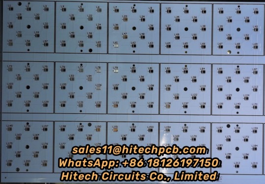
Aluminium PCB
1. What’s Aluminium LED PCB?
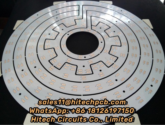
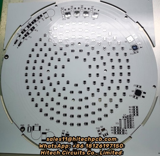
Aluminum LED PCB substrate is a metal - based copper-clad sheet with good heat dissipation. A single panel is generally composed of three layers of structure, namely the circuit layer (copper foil), insulation layer and metal base layer. It is commonly found in LED lighting products. There are two sides, the white side is used to weld the LED pins, and the other side is the natural color of aluminum, which is usually coated with heat-conducting gel and then in contact with the heat-conducting part. Among all metal core PCBS, Aluminum LED PCB is the most common type. The base material consists of an aluminum core and standard FR4. It features a thermal cladding that dissipates heat in an efficient manner while cooling components and improving the overall performance of the product. Currently, aluminum-backed PCBS are considered solutions for high power and tight tolerance applications.
2. Aluminum LED PCB with Copper Layer, Dielectric Layer & Aluminum Layer
Aluminum LED PCB has a similar layout to any other printed circuit boards with copper layer(s), solder mask layer(s) and silkscreen(s). Instead of having a fiberglass or plastic substrate, Aluminum LED PCB is made from metal core substrate, which consists of copper layer, dielectric layer and aluminum layer. This substrate is called as Aluminum based copper clad laminate (CCL). The glass reinforced and ceramic filled dielectric layer in-between copper layer and aluminum layer is very thin, but plays a very important role of electric insulation and thermal conductivity (because of minimum thermal resistance) from copper layer to aluminum base. The copper is etched into conductors and metal base is to withdraw thermal (/heat). The superior heat transfer capacity of Aluminum-based PCB helps cooling components while eliminating problems associated with managing fragile ceramics.
3. Thermal conductivity of Aluminium LED PCB
The general thermal conductivity of Aluminum LED PCB is 0.3, 0.6, 1.0, 1.5, 2.0, 3.0, 5.0, 122W/m.k, etc., among which 0.3-1.0w /m.k is the general conductive Aluminum LED PCB, 1.5W/m.k is the middle conductive Aluminum LED PCB, 2.0-3.0w /m.k is the high conductive Aluminum LED PCB. 5.0W/m.k is thin abasal substrate, and 122W/m.k is ultra-high conductivity Aluminum LED PCB, also known as ALC Aluminum LED PCB.
At present, the common Aluminum LED PCB on the market has a thermal conductivity of 1.0, 1.5, 2.0W/m.k high conductivity type Aluminium LED, wherein the thermal conductivity of 1.0W/m.k Aluminum LED PCB is called general Aluminum LED PCB, its insulation layer is composed of epoxy glass cloth bonded sheet; Aluminum LED PCB with thermal conductivity of 1.5W/m.k is called high heat dissipation Aluminum LED PCB, and its insulation layer is composed of epoxy resin or other resins with high thermal conductivity; The Aluminum LED PCB with a thermal conductivity of 2.0W/m.k is called the Aluminum LED PCB for high-frequency circuit, and the insulating layer is composed of polyolefin resin or Polyimide resin glass cloth bonded sheet. The thermal conductivity of Aluminum LED PCB varies according to the copper layer in the circuit. Different processes produce different levels of thermal conductivity.
We currently support Aluminum based CCLs from Ventec, GDM and BoYu with thermal conductivity from 1.0 ~ 7 W/m•K. The Aluminum LED PCB prices of Ventec is much higher than that with GDM and BOYU since material cost, and the prices of high thermal conductivity is higher than low thermal conductivity. Hitechpcb provides a wide range of electrical and thermally conductive interface pads, thermally conductive gap filler, thermal phase change materials and thermally conductive electrically insulating materials, as well as specialized equipment for high volume Aluminum LED PCB manufacturing. Choosing Hitech Circuits PCB as your Aluminum LED PCB supplier, just send your Gerber files and fabrication notes to us, we will deliver qualitied PCB boards to you on time.
4. Dielectric Constant of Aluminium LED PCB
The dielectric constant of Aluminum LED PCB substrate is a special detection method for Aluminum LED PCB. It is a variable Q value series resonance method through the measurement of dielectric constant and dielectric loss factor. The sample and tuning capacitor are connected in series to the high frequency circuit to measure the series circuit The principle of Q value.
The performance of Aluminum LED PCB includes requirements such as peel strength, surface resistivity, minimum breakdown voltage, dielectric constant, flammability and thermal resistance.
5. Aluminum LED PCB with White Solder Mask
The retail price of Aluminum LED lights has dropped dramatically in recent years, while the energy efficiency and brightness of LED lights have improved. These technological advances have led some to predict annual growth of 45% over the next five years. With the development of the LED industry, the demand for LED PCBS and solder masks is also increasing. Solder shield is a protective coating applied to exposed printed circuit boards. The exposed PCB board is covered with a mask to prevent accidental solder bridging during PCB assembly and to protect the PCB from the environment. Solder masks are traditionally green, and are expected to withstand the high temperatures that occur in reflow soldering, as different colors such as blue, red, or black will occasionally appear. Increased production of Hitch Aluminum LED PCB requires increased whiteness and color stability of the mask. Aluminum LED PCB commonly used LPI welding color is white and black, of which white welding color is the most commonly used to achieve high brightness and perfect light reflection. White Aluminum LED PCB ensures no darkening and will not affect the color temperature of LED smd. At the same time, it also helps to increase the life of LED applications. Looking for reliable Aluminum LED PCB suppliers, Hitech is a good choice.
6. Classification of Aluminum LED PCB Substrate
Aluminum LED PCB-based copper clad plates are divided into three categories:
The first is the universal aluminum-based copper clad plate, the insulation layer is composed of epoxy glass cloth bonded sheet;
The second is the high heat dissipation aluminum-based copper-clad plate, the insulation layer is composed of high thermal conductivity epoxy resin or other resins;
Third, high frequency circuit aluminum base copper plate, insulation layer by polyolefin resin or Polyimide resin glass cloth bonded sheet.
The biggest difference between aluminum clad copper plate and conventional FR-4 clad copper plate is heat dissipation. Compared with 1.5mm thickness of FR-4 clad copper plate and aluminum clad copper plate, the former thermal resistance of 20 ~ 22 ℃, the latter thermal resistance of 1.0 ~ 2.0℃, the latter is much smaller.
7. Aluminum LED PCB Performance:
(1) Heat dissipation
Many double panel, multi - layer plate high density, power, heat distribution is difficult. Conventional printed board substrates such as FR4, CEM3 are bad conductors of heat, insulation between layers, heat does not escape. Local heating of electronic equipment is not excluded, leading to high temperature failure of electronic components, and Aluminum LED PCB can solve this problem of heat dissipation.
(2) Thermal Expansibility
Thermal expansion and cold contraction is the common nature of substances, and the coefficient of thermal expansion of different substances is different. Aluminum based printed board can effectively solve the problem of heat dissipation, so that the printed board components of different substances on the thermal expansion and contraction problem, improve the durability and reliability of the whole machine and electronic equipment. Especially solve SMT (surface mount technology) thermal expansion and shrinkage problems.
(3) Dimensional stability
Aluminum-based printed boards are obviously much more stable in size than those made of insulating materials. Aluminum base printed board, aluminum sandwich board, heating from 30℃ to 140~150℃, the size change is 2.5~3.0%.
(4) Other reasons
Aluminum based printed board, with shielding effect; Instead of brittle ceramic substrate; Safe use of surface mounting technology; Reducing the real effective area of the printed board; Instead of radiator and other components, improve the heat resistance and physical properties of products; Reduce production costs and labor.
8. Why choose Aluminum LED PCB from Hitechpcb? What are the advantages of Aluminum LED PCB?
(1) Good heat dissipation performance: Aluminum LED PCB can reduce the thermal resistance to the minimum, has a smaller thermal resistance, thermal expansion coefficient is closer to copper foil, so that Aluminum LED PCB has excellent thermal conductivity and heat dissipation performance, reduce the module operating temperature, prolong the service life.
High current load: Using the same thickness, the same line width, Aluminum LED PCB substrate can carry higher current.
(2) Good machinability: can replace ceramic substrate, better mechanical endurance. At the same time, high strength and toughness, can realize large area printed board manufacturing and component mounting.
(3) Good electromagnetic shielding: In order to ensure the performance of electronic circuits, some components of electronic products need to prevent electromagnetic radiation and interference. Aluminum LED PCB can act as a shield plate, play the role of shielding electromagnetic wave
(4) Environmental protection: The Aluminum LED PCB used in the raw material is non-toxic and can be recycled. Meet RoHs requirements.
(5)Light weight: Aluminum LED PCB has a surprisingly light weight with excellent strength and elasticity, which is very convenient.
Hitech Circuits can provide high quality and affordable Aluminum LED PCB products for you.
9. Technical requirements for Aluminum LED PCB
The main technical requirements are:
1. Dimensional requirements: including panel size and deviation, thickness and deviation, perpendicularity and warpage; Appearance, including cracks, scratches, burrs and delimitation, aluminum oxide film, etc.
2. Performance requirements, including peel strength, surface resistively, minimum breakdown voltage, dielectric constant, combustion and thermal resistance requirements.
10. Special test method for Aluminum-based copper clad plates
One is the measurement method of dielectric constant and dielectric loss factor. It is the series resonance method with variable Q value. The sample and tuned capacitor are connected to the high-frequency circuit in series to measure the Q value of the series circuit.
The other is the measurement method of thermal resistance, which is calculated by the ratio of temperature difference and heat conduction between different temperature measurement points.
11. The Aluminum LED PCB manufacturing process in Hitechpcba
(1)Substrate cutting
a. cutting process: material → cutting
b. Note: ① Check the size of the first piece; ② Pay attention to Aluminum surface scratching and copper surface scratching; ③ Pay attention to the layering of the board edge and the tip.
(2)Plate drilling
a, drilling process: pin → drilling → inspection plate
b, matters needing attention: ① check the number of drilling holes, the size of the empty chestnut chain; ② Check the plate burr, hole deviation; ③ Avoid scratching the substrate; ④ Check and replace the drill nozzle.
(3) Imaging transfer
a, graphic imaging process: grinding plate → film → exposure → development
b, precautions: ① Check whether there is an open circuit after development; ② Pay attention to the poor line caused by the board wipe; ③ There can be no air residual exposure to prevent poor exposure; ④ Whether there is deviation in developing counterpoint; ⑤ After exposure, the development should be done at rest for more than 15 minutes.
(4)Solder mask and Silkscreen process
a, kill row silk printing resistance welding, character process: screen printing → pre-baking → exposure → development → character
b, matters needing attention: ① Check whether there is foreign body on the board; ② Pay attention to the cleaning of the net board; ③ Pre-bake for more than 30 minutes after screen printing, to avoid bubbles in the line; ④ Pay attention to the thickness and uniformity of screen printing; ⑤ After the pre-baked plate to completely mutual cooling, avoid touching film or damage to the ink surface gloss.
(5)E-test or flying probe test
a, test process: line test → withstand voltage test
b, precautions: ① How to distinguish after the test how to store qualified and unqualified products.
(6)FQC, FQA, packaging, shipping
a. Process: FQC→FQA→ Packaging → shipping
b. Note: ① FQC should pay attention to the confirmation of the appearance of the finished Aluminum LED PCB in the process of eye inspection and make a reasonable distinction; ② FQA does spot check and verify the inspection standards of FQC; ③ We should confirm the number of packages to avoid mixed plates, wrong plates and package
12. Application of Aluminum LED PCB
1. Audio devices: input, output amplifier, balance amplifier, audio amplifier, preamplifier, power amplifier.
2. Power Supply: switching voltage regulator, DC/AC converter, SW voltage regulator, etc.
3. Communication electronic equipment: high frequency amplifier, filter, transmitter circuit
4. Office automation equipment: motor drive, etc
5. Automobile: electronic regulator, ignition device, power controller, etc.
6. Computer :CPU board, floppy disk drive, power equipment, etc.
7. Power module: converter, solid relay, rectifier bridge, etc
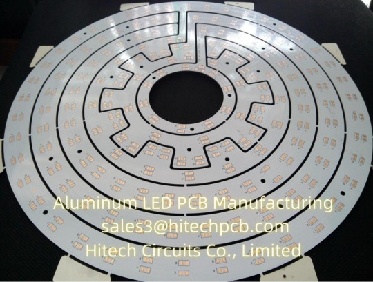
8. Lamps and lighting: A variety of colorful LED energy-saving lamps are well received by the market, and Aluminum LED PCB used in LED lights has also begun to be applied on a large scale.
13. Aluminum LED PCB Storage Conditions
Aluminum LED PCB are generally stored in a dark and dry environment. Most Aluminum LED tube lighting metal core pcb are prone to dampness, yellowing, and blackening. Generally, they should be used within 48 hours after opening the vacuum package.
14. Specification for the manufacture of Aluminum LED PCB
a. Aluminum LED PCB is often used in power devices, power density is high, so the copper foil is thicker. If copper foils over 3oz are used, the etching of thick copper foils requires engineered line width compensation, otherwise the line width will be out of tolerance after etching.
b. The aluminum base surface of aluminum substrate must be protected by protective film in advance during PCB processing, otherwise, some chemicals will etch the aluminum base surface, resulting in appearance damage. And the protective film is easy to be hurt, resulting in gaps, which requires the whole PCB processing process must be inserted.
c. The hardness of the milling cutter used by the glass fiber board gong board is relatively small, and the hardness of the milling cutter used by the aluminum substrate is large. In the process of manufacturing glass fiber board milling cutter speed, while the production of aluminum substrate is at least two thirds slower.
d, computer milling glass fiber board is just the use of the machine's own cooling system, but the processing of aluminum substrate must be in addition to alcohol heat dissipation for the gong head.
15. Aluminum LED PCB circuit fabrication
(1) Mechanical processing: Drilling of aluminum substrate can be done, but no burr is allowed on the edge of the inner hole after drilling, which will affect the pressure test. Milling the shape is very difficult. And punching shape, need to use advanced mold, mold production is very skilled, as one of the difficulties of aluminum substrate. After shape punching, the edge should be very neat, without any burr, and do not hurt the welding resistance layer on the edge of the plate. Usually the use of soldier die, hole from the line, shape from the aluminum surface, circuit board punching force is cut down, and so on are skills. After punching the shape, the warpage of the board should be less than 0.5%.
(2) The whole production process is not allowed to wipe the aluminum base surface: aluminum base touch, or by a certain chemical will produce surface discoloration, blackening, which is absolutely unacceptable, re-polishing aluminum base some customers do not receive, so the whole process does not touch the aluminum base surface is one of the difficulties in the production of aluminum base plate. Some enterprises use passivation process, some in hot air leveling (spray tin) before and after each pasted protective film.
(3) Over-high voltage test: the aluminum base board of the communication power supply shall be tested at 100% high voltage. Some customers require direct current or alternating current. The voltage shall be 1500V or 1600V, and the time shall be 5 seconds or 10 seconds. Dirt on the board, holes and aluminum edge burr, line saw tooth, damage to any little insulation layer will lead to high voltage test fire, leakage, breakdown. Pressure test board stratification, foaming, are rejected.
1 note
·
View note
Text
What’s Aluminium LED PCB?
Aluminum LED PCB substrate is a metal - based copper-clad sheet with good heat dissipation. A single panel is generally composed of three layers of structure, namely the circuit layer (copper foil), insulation layer and metal base layer. It is commonly found in LED lighting products. There are two sides, the white side is used to weld the LED pins, and the other side is the natural color of aluminum, which is usually coated with heat-conducting gel and then in contact with the heat-conducting part. Among all metal core PCBS, Aluminum LED PCB is the most common type. The base material consists of an aluminum core and standard FR4. It features a thermal cladding that dissipates heat in an efficient manner while cooling components and improving the overall performance of the product. Currently, aluminum-backed PCBS are considered solutions for high power and tight tolerance applications.
2. Aluminum LED PCB with Copper Layer, Dielectric Layer & Aluminum Layer
Aluminum LED PCB has a similar layout to any other printed circuit boards with copper layer(s), solder mask layer(s) and silkscreen(s). Instead of having a fiberglass or plastic substrate, Aluminum LED PCB is made from metal core substrate, which consists of copper layer, dielectric layer and aluminum layer. This substrate is called as Aluminum based copper clad laminate (CCL). The glass reinforced and ceramic filled dielectric layer in-between copper layer and aluminum layer is very thin, but plays a very important role of electric insulation and thermal conductivity (because of minimum thermal resistance) from copper layer to aluminum base. The copper is etched into conductors and metal base is to withdraw thermal (/heat). The superior heat transfer capacity of Aluminum-based PCB helps cooling components while eliminating problems associated with managing fragile ceramics.
3. Thermal conductivity of Aluminium LED PCB
The general thermal conductivity of Aluminum LED PCB is 0.3, 0.6, 1.0, 1.5, 2.0, 3.0, 5.0, 122W/m.k, etc., among which 0.3-1.0w /m.k is the general conductive Aluminum LED PCB, 1.5W/m.k is the middle conductive Aluminum LED PCB, 2.0-3.0w /m.k is the high conductive Aluminum LED PCB. 5.0W/m.k is thin abasal substrate, and 122W/m.k is ultra-high conductivity Aluminum LED PCB, also known as ALC Aluminum LED PCB.
At present, the common Aluminum LED PCB on the market has a thermal conductivity of 1.0, 1.5, 2.0W/m.k high conductivity type Aluminium LED, wherein the thermal conductivity of 1.0W/m.k Aluminum LED PCB is called general Aluminum LED PCB, its insulation layer is composed of epoxy glass cloth bonded sheet; Aluminum LED PCB with thermal conductivity of 1.5W/m.k is called high heat dissipation Aluminum LED PCB, and its insulation layer is composed of epoxy resin or other resins with high thermal conductivity; The Aluminum LED PCB with a thermal conductivity of 2.0W/m.k is called the Aluminum LED PCB for high-frequency circuit, and the insulating layer is composed of polyolefin resin or Polyimide resin glass cloth bonded sheet. The thermal conductivity of Aluminum LED PCB varies according to the copper layer in the circuit. Different processes produce different levels of thermal conductivity.
We currently support Aluminum based CCLs from Ventec, GDM and BoYu with thermal conductivity from 1.0 ~ 7 W/m•K. The Aluminum LED PCB prices of Ventec is much higher than that with GDM and BOYU since material cost, and the prices of high thermal conductivity is higher than low thermal conductivity. Hitechpcb provides a wide range of electrical and thermally conductive interface pads, thermally conductive gap filler, thermal phase change materials and thermally conductive electrically insulating materials, as well as specialized equipment for high volume Aluminum LED PCB manufacturing. Choosing Hitech Circuits PCB as your Aluminum LED PCB supplier, just send your Gerber files and fabrication notes to us, we will deliver qualitied PCB boards to you on time.
4. Dielectric Constant of Aluminium LED PCB
The dielectric constant of Aluminum LED PCB substrate is a special detection method for Aluminum LED PCB. It is a variable Q value series resonance method through the measurement of dielectric constant and dielectric loss factor. The sample and tuning capacitor are connected in series to the high frequency circuit to measure the series circuit The principle of Q value.
The performance of Aluminum LED PCB includes requirements such as peel strength, surface resistivity, minimum breakdown voltage, dielectric constant, flammability and thermal resistance.
5. Classification of Aluminum LED PCB Substrate
Aluminum LED PCB-based copper clad plates are divided into three categories:
The first is the universal aluminum-based copper clad plate, the insulation layer is composed of epoxy glass cloth bonded sheet;
The second is the high heat dissipation aluminum-based copper-clad plate, the insulation layer is composed of high thermal conductivity epoxy resin or other resins;
Third, high frequency circuit aluminum base copper plate, insulation layer by polyolefin resin or Polyimide resin glass cloth bonded sheet.
The biggest difference between aluminum clad copper plate and conventional FR-4 clad copper plate is heat dissipation. Compared with 1.5mm thickness of FR-4 clad copper plate and aluminum clad copper plate, the former thermal resistance of 20 ~ 22 ℃, the latter thermal resistance of 1.0 ~ 2.0℃, the latter is much smaller.
6. Aluminum LED PCB Performance:
(1) Heat dissipation
Many double panel, multi - layer plate high density, power, heat distribution is difficult. Conventional printed board substrates such as FR4, CEM3 are bad conductors of heat, insulation between layers, heat does not escape. Local heating of electronic equipment is not excluded, leading to high temperature failure of electronic components, and Aluminum LED PCB can solve this problem of heat dissipation.
(2) Thermal Expansibility
Thermal expansion and cold contraction is the common nature of substances, and the coefficient of thermal expansion of different substances is different. Aluminum based printed board can effectively solve the problem of heat dissipation, so that the printed board components of different substances on the thermal expansion and contraction problem, improve the durability and reliability of the whole machine and electronic equipment. Especially solve SMT (surface mount technology) thermal expansion and shrinkage problems.
(3) Dimensional stability
Aluminum-based printed boards are obviously much more stable in size than those made of insulating materials. Aluminum base printed board, aluminum sandwich board, heating from 30℃ to 140~150℃, the size change is 2.5~3.0%.
(4) Other reasons
Aluminum based printed board, with shielding effect; Instead of brittle ceramic substrate; Safe use of surface mounting technology; Reducing the real effective area of the printed board; Instead of radiator and other components, improve the heat resistance and physical properties of products; Reduce production costs and labor.
7. Why choose Aluminum LED PCB from Hitechpcb? What are the advantages of Aluminum LED PCB?
(1) Good heat dissipation performance: Aluminum LED PCB can reduce the thermal resistance to the minimum, has a smaller thermal resistance, thermal expansion coefficient is closer to copper foil, so that Aluminum LED PCB has excellent thermal conductivity and heat dissipation performance, reduce the module operating temperature, prolong the service life.
High current load: Using the same thickness, the same line width, Aluminum LED PCB substrate can carry higher current.
(2) Good machinability: can replace ceramic substrate, better mechanical endurance. At the same time, high strength and toughness, can realize large area printed board manufacturing and component mounting.
(3) Good electromagnetic shielding: In order to ensure the performance of electronic circuits, some components of electronic products need to prevent electromagnetic radiation and interference. Aluminum LED PCB can act as a shield plate, play the role of shielding electromagnetic wave
(4) Environmental protection: The Aluminum LED PCB used in the raw material is non-toxic and can be recycled. Meet RoHs requirements.
(5)Light weight: Aluminum LED PCB has a surprisingly light weight with excellent strength and elasticity, which is very convenient.
Hitech Circuits can provide high quality and affordable Aluminum LED PCB products for you.
0 notes
Last Seen Blogs