#BLE and WiFi
Explore tagged Tumblr posts
Visit Tumblr Blog
Explore Tumblr blogs with no restrictions, modern design and the best experience.
Last Seen Tumblr Blogs


Fun Fact
Celebrities use Tumblr as well.
Text
WIRELESS MODULE with BLE and WiFi – ESP32-C3-DevKitM-1 The ESP32-C3-DevKitM-1 from Campus Component is a low-power, cost-effective solution for IoT developers. It combines WiFi and Bluetooth LE connectivity in a compact design. Featuring robust security features and efficient processing capabilities, this board is suitable for smart home devices, health monitors, and industrial IoT systems. It supports Espressif’s ESP-IDF framework.
0 notes
Text

Espressif ESP32-C3-AWS-ExpressLink-DevKit: Seamless Cloud Connectivity for IoT Developers
Explore the Espressif ESP32-C3-AWS-ExpressLink-DevKit—an IoT development board with built-in AWS IoT ExpressLink support. Discover how to simplify secure cloud connectivity for smart devices using this compact, RISC-V-based Wi-Fi and Bluetooth module.
0 notes
Text
bro i fucking hate c++ what do you mean i cant declare an array of a cosmic mishmash of any random variable type of unknown size, and then query whats in it by doing if item in list style statement. what do you mean compiled languages are fundamentally different to interpreted languages. what Do You MEAN
#.txt#can you tell i use python for basically everything#but bro i would use it for this (seeed wio terminal) except that the wifi and ble module isnt compatible lol#i love how its advertised as compatible with micro/circuit py and then when u wanna use wifi or ble its like lol sike#so here i am. digging my way thru cpp code that looks like my own personal hell#im being really brave about it though
0 notes
Text
This is basically the current main board but with an e-ink display, I agree with the author of the article that this board would probably be very good for messaging even outside. So I'm thinking about input method possibilities for our current board that we could potentially apply to this later on to make it so you could have a handheld PierMesh e2ee (the e2ee might take some futzing around/soldering a coprocessor) messaging device without a phone or anything else.
4 notes
·
View notes
Text
OOOh, some hot new chips just dropped into our mailbox - ESP32-P4! 🔥🚀
Espressif's latest chip has a snazzy eval board, and we just snagged a couple for CircuitPython development. The P4 is a RISC V dual core 400MHz processor with CSI/DSI support, USB HS, and Ethernet too. This chip doesn't have BLE or WiFi like all the other ESP chips. Instead, it uses a low-cost ESP32-C5 module as a wireless co-processor. The eval board is sorta shaped like a Raspberry Pi and has various A/V connections. We also got 100 sample chips of the 16MB in-package PSRAM variety, so we can start designing our first board. Shall we do a Feather? a Metro? maybe a Pi Zero-shaped thingy?
#espressif#esp32#ESP32P4#espfriends#adafruit#greetz#circuitpython#hardwaredesign#microcontroller#techinnovation#riscv#developmentboard#diyelectronics#opensourcehardware#embeddedsoftware#chipdesign
3 notes
·
View notes
Text
Specialist - Industrial IoT
Job title: Specialist – Industrial IoT Company: LTIMindtree Job description: of virtualization including deployment and lifecycle management Experience with IoT Sensors cellular LoRaWAN BLE WiFi… BU Instrumentation Electrical roles BU Operations Engineering Azure IoT Hub LoRaWAN Network Servers MQTT Sparkplug B Ignition Aveva PI… Expected salary: Location: Navi Mumbai, Maharashtra Job date: Wed,…
0 notes
Text
ESP32-S3-Matrix von Waveshare: Kompaktes Board mit 8x8 RGB-LED-Matrix im Test

Das kleine ESP32-S3-Matrix Board von Waveshare kombiniert moderne Mikrocontroller-Technik mit einer integrierten 8x8 RGB-LED-Matrix – ideal für kreative LED-Projekte, coole Animationen oder einfache Pixelspiele. In diesem Beitrag zeige ich dir, was mit diesem kompakten Board alles möglich ist. https://youtu.be/RxWwx_eNJn8 Du erfährst, wie du das Board schnell in Betrieb nimmst und programmierst – wahlweise über die Arduino IDE oder mit Visual Studio Code. Danach wird’s praktisch: Wir erstellen gemeinsam verschiedene Lichteffekte und Animationen auf der integrierten LED-Matrix. So bekommst du nicht nur einen Eindruck von der Vielseitigkeit des Boards, sondern auch direkt Inspiration für eigene Projekte.


Technische Daten des ESP32-S3-Matrix von Waveshare
Hier zunächst die technischen Daten des Boards: EigenschaftDetailsMikrocontrollerESP32-S3 mit Xtensa® 32-bit LX7 Dual-Core ProzessorTaktfrequenzBis zu 240 MHzArbeitsspeicher (RAM)512 KB SRAMROM384 KBRTC-SRAM16 KBFlash-Speicher4 MBFunkverbindungen2.4 GHz WiFi, Bluetooth Low Energy (BLE)AnschlussUSB Type-CGPIO-Pins20 digitale Ein-/Ausgänge (über Pinheader)Anzeigeeinheit8x8 RGB-LED-Matrix (64 LEDs insgesamt)BesonderheitenNiedriger Energieverbrauch, integrierte Antenne, hohe RF-LeistungHinweis zur LED-MatrixHelligkeit nicht zu hoch einstellen – Hitzeentwicklung kann das Board schädigen

ESP32-S3 Chip auf dem ESP32-S3-Matrix Board von Waveshare
Bezug des Mikrocontrollers
Du bekommst diesen Mikrocontroller auf eBay.de bereits ab ca. 8 € zzgl. Versandkosten*. Wenn du etwas sparen möchtest und etwas Geduld mitbringst, lohnt sich ein Blick auf AliExpress.com – dort ist das Board bereits ab rund 6 € zzgl. Versand erhältlich. Hinweis von mir: Die mit einem Sternchen (*) markierten Links sind Affiliate-Links. Wenn du über diese Links einkaufst, erhalte ich eine kleine Provision, die dazu beiträgt, diesen Blog zu unterstützen. Der Preis für dich bleibt dabei unverändert. Vielen Dank für deine Unterstützung! Lieferumfang Der Mikrocontroller wird in einer kleinen antistatischen Tüte geliefert ohne Pinleisten. Du musst dir somit noch zusätzlich eine 2,54mm Stiftleisten* besorgen. Diese Stiftleisten gibt es ebenso recht günstig auf Aliexpress oder ebay.de.
Pinout & Aufbau des Mikrocontrollers
Nachfolgend siehst du das Pinout des Mikrocontrollers. Besonders positiv fällt auf, dass es einen deutlich gekennzeichneten 5V-Pin gibt – das ist bei Mikrocontrollern der ESP32-Familie eher selten.

Pinout - ESP32-S3 Matrix Abgesehen davon sind nahezu alle GPIOs vielseitig nutzbar: Sie unterstützen UART, PWM, I2S, ADC, I2C und SPI-Kommunikation. Zusätzlich ermöglichen die beiden Pins unten rechts, TX und RX, die serielle Kommunikation mit anderen Geräten – etwa für Debugging-Zwecke oder die Anbindung externer Module. Aufbau der RGB LED Matrix Die RGB-LED-Matrix auf dem ESP32-S3-Matrix Board ist fest verlötet und folgt einem 8x8-Raster, also 64 einzeln adressierbaren LEDs. Standardmäßig ist die Matrix intern mit GPIO 14 des Mikrocontrollers verbunden – diesen Pin müssen wir auch in unserem Sketch angeben, um die LEDs korrekt anzusteuern. Die erste LED (Index 0) befindet sich dabei oben links, direkt neben dem USB-Anschluss, in der ersten Zeile. Von dort aus verläuft die Adressierung zeilenweise nach rechts, also in sogenannter „serienmäßiger Reihenfolge“ (row-major order). Das ist wichtig zu wissen, wenn man später eigene Muster oder Animationen umsetzen möchte.

Programmierung des Boards ESP32-S3-Matrix
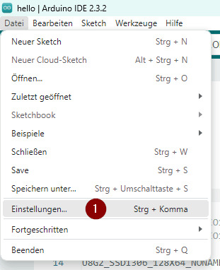
In der offiziellen englischen Dokumentation zum Board von Waveshare wird dir erläutert wie du dieses Board in der Arduino IDE, Visual Studio Code, Espressif IDF sowie MicroPython programmierst. Ich möchte dir nachfolgend meinen Weg aufzeigen wie ich diesen in der Arduino IDE zum laufen gebracht und programmiert habe. Achtung: Helligkeit nicht zu hoch einstellen Ein wichtiger, aber leicht zu übersehender Hinweis findet sich in einem der Beispielsketches von Waveshare: Die Helligkeit der RGB-LED-Matrix sollte nicht zu hoch eingestellt werden, da sich das Board sonst stark erwärmen kann. Durch die kompakte Bauweise und die hohe Leistungsaufnahme der LEDs besteht die Gefahr, dass sich die Temperatur schnell erhöht – was auf Dauer zu einer Beschädigung der Platine führen kann. Programmieren in der Arduino IDE Die Entwicklungsumgebung Arduino IDE ist für die Mikrocontroller der Arduino-Familie (wie der Name es erahnen lässt) ausgelegt. Damit wir den Mikrocontroller mit dem ESP32-S3 Chip programmieren können, müssen wir zunächst den Boardtreiber installieren. Installieren des Boardtreibers für Espressif Chips Im ersten Schritt öffnen wir die Einstellungen – entweder über das Hauptmenü Datei > Einstellungen oder mit der Tastenkombination Strg + , (Komma).


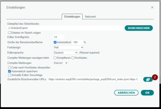
In den Einstellungen klicken wir auf die in der zweiten Grafik markierte Schaltfläche (2), um den Dialog „Zusätzliche Boardverwalter-URLs“ zu öffnen. Dort fügen wir die folgende URL ein und bestätigen mit OK: https://espressif.github.io/arduino-esp32/package_esp32_index.json Sobald dieser Schritt abgeschlossen ist, kannst du den Boardverwalter über das linke Menü (6) öffnen und dort nach „esp32“ suchen (7). In der Ergebnisliste sollte der Eintrag „esp32 von Espressif Systems“ erscheinen. Wähle dort die Schaltfläche „INSTALLIEREN“ (8), um die Boarddefinitionen zu installieren.


Die Installation kann etwas Zeit in Anspruch nehmen, da es zahlreiche Varianten des ESP32 gibt und alle benötigten Treiber von einem eher langsamen Server heruntergeladen werden. Bei mir hat der Vorgang rund 5 Minuten gedauert. Den Fortschritt der Installation kannst du im Fenster „Ausgabe“ mitverfolgen. Damit sind die benötigten Boardtreiber installiert. Du findest nun unter Werkzeuge > Board > esp32 eine große Auswahl an ESP32-Boards. Für das hier verwendete Board wählen wir den Eintrag „ESP32-S3 Dev Module“ aus.

Programmieren der 8x8 RGB Matrix mit der Adafruit NeoPixel Bibliothek Wie man eine RGB-LED vom Typ WS2812B am Mikrocontroller ansteuert, habe ich bereits in mehreren Beiträgen gezeigt. Besonders einfach gelingt das mit der Adafruit NeoPixel Bibliothek, die ich auch in diesem Beispiel wiederverwende. - RGB Beleuchtung einfach steuern: NeoPixel Ring mit Arduino - Arduino Lektion 31: 12bit RGB NeoPixel Ring - LED-Würfel: Zufallszahlen auf der Pixelmatrix darstellen Du kannst die Bibliothek ganz bequem über den Bibliotheksverwalter der Arduino IDE installieren – inklusive aller nötigen Abhängigkeiten (engl. dependencies). Suche dazu einfach nach „Adafruit NeoPixel“ und klicke auf Installieren. Hilfsfunktion zum ansteuern einer LED via X & Y Koordinate Um eine einzelne LED auf der Pixelmatrix anzusteuern, benötigen wir ihren Index im Array. Dieser beginnt oben links bei 0 und endet unten rechts bei 63. Das direkte Arbeiten mit diesen eindimensionalen Indizes kann beim Zeichnen von Figuren jedoch schnell unübersichtlich und fehleranfällig werden. Deshalb habe ich mir eine kleine Hilfsfunktion erstellt, mit der man stattdessen über X- und Y-Koordinaten arbeiten kann. Dabei steht X für die Spalte und Y für die Zeile, was dem gewohnten Koordinatensystem entspricht. So lässt sich die Positionierung einzelner Pixel deutlich klarer und intuitiver gestalten, besonders beim Aufbau grafischer Muster in einem zweidimensionalen Array. // Gerade Verdrahtung: Zeile für Zeile von links nach rechts uint16_t xy(uint8_t x, uint8_t y) { // Die LED-Matrix ist 8 Spalten (x) breit und 8 Zeilen (y) hoch. // Die LEDs sind zeilenweise verdrahtet – also: // erste Zeile von links nach rechts (x = 0 bis 7), // dann zweite Zeile direkt danach, usw. // Um die Position (x, y) auf den eindimensionalen LED-Array-Index (0–63) zu berechnen, // multiplizieren wir die Zeilennummer mit 8 (Anzahl Spalten), um den Zeilen-Offset zu bekommen: // y * 8 = Startposition dieser Zeile im Array // Dann addieren wir die Spaltennummer x hinzu: // So ergibt sich die konkrete LED-Nummer in der 1D-LED-Liste return y * 8 + x; // Beispiel: // x = 3, y = 2 → 2. Zeile = Offset 16 → Index = 16 + 3 = 19 // Das bedeutet: Pixel an Spalte 3, Zeile 2 → LED Nr. Read the full article
0 notes
Text
the tvs wifi cut in the middle of the rey addressing ch*d g*ble 😑
0 notes
Text
ESP32-C3 BLE / WiFi dev board with 0.42-inch OLED notes
I got some ESP32-C3 dev boards with built-in OLED screens for a Halloween costume project, and I've been troubled by the lack of documentation and general information about both the ESP32-C3 platform and the board, so here are some notes for future hackers:
OLED type is SH1106, not SSD1306, as seen in some forum posts and even in the blurry screenshot that accompanies these boards. Specifically, the U8G2 constructor for this board is U8G2_SH1106_72X40_WISE_F_HW_I2C(). With the SSD1306 driver, the screen pixels are shifted to the left and there's a column or two of corrupted data on the right-hand-side of the OLED screen.
Apparently the ESP32-C3 chip cannot measure its supply voltage internally, something that even ATtiny chips can do :(
Proper Arduino configuration is:
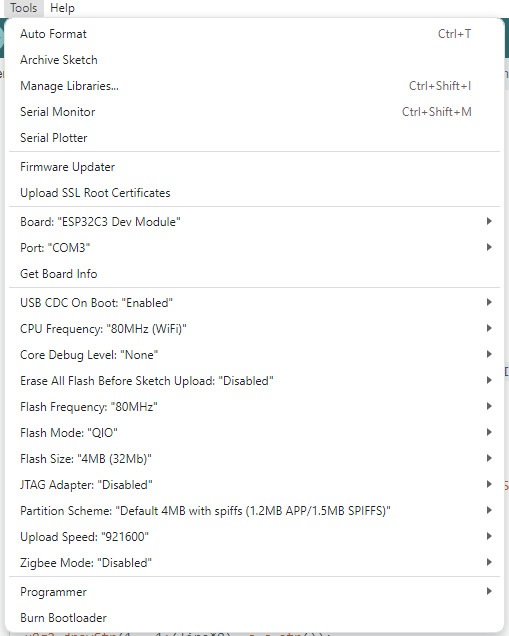
(CPU frequency and partition setup are of course configurable).
I'm not sure yet if I2C is actually hardware-offloaded here, but the pins are apparently non-default, with SDA=5, SCL=6. At least the display speed doesn't change at all when changing the I2C frequency. I don't have the equipment to measure this, but so far it looks like I2C clock speed is ignored. Anyway, I can get about 73 FPS, or about 11ms per frame draw on the built-in 72x40 OLED.
But overall, looks like a nice dev board, and it's neat that it's powered by a RISC-V microcontroller. Perfect for hobby projects that don't need many pins.
Buy the board here.
0 notes
Text
Stroop Test, dual tasking, cognitive skills, country flags, capitals, “word salad” and mathematic tasks in various levels
perceived exertion with BORG, modified BORG and pain scale
cursor function for scanning data second by second and comparing with overlay file
optional upgrade to gaitway® 3d including 3-component force (Fz, Fx, Fy), torque, pressure distribution (incl. foot rotation and roll-off analysis etc), “virtual split-belt” function and interface combination with 3D Motion Capture (MoCap), EMG ElectroMyoGraphy, video, IMU Inertial Measurement Unit, etc. (not for torqualizer® ergometer)
optional auto-speed control upgrade and software via Microgate Optogait LED bars so the speed is controlled automatically based on the position of the runner or cyclist
optional perturbation mode (not for torqualizer ergometer)
optional metronome function for acoustic cueing (not for torqualizer® ergometer)
step count, step length and step frequency / cadence function and display (not for oversize treadmills and not for torqualizer® ergometer)
screenshot function (.PNG) for point of interest saves picture of the screen on USB stick and in the summary report
new scales for the graphs of load/heart rate parameters and Poincare HRV display
treadmill/ergometer serial numbers and firmware version in the screen
summary report export in PDF and .csv spread sheet with 1 button only
new summary report in table form with valuable data for better traceability and data management, also including now the screenshots made during the tests and exercise.
exported files (PDF, .CSV) with clear file name proposal incl. date code, treadmill model name and serial number, etc.
step count, step length and step frequency (cadence) function and display
changeable displays e.g. with count down display for various parameters
included exercise profiles scalable and editable and free memory space for user defined exercise profiles
included test profiles / protocols such as Bruce, modified Bruce, Graded Test, Naughton, Cooper, Balke, Super Balke, Ellestad A, Ellestad B, Gardner, UKK 2 km WalkTest, Conconi, Ramp, Fitkids, Chester Treadmill Walk, VO2 / 10k, VO2 / 11k, VO2 / 12k, VO2 / 14k, various Interval Tests incl. progressive interval, various Pyramid Tests, Hochfelln mountain protocol, etc.
optional import of GPS/GPX data to convert to treadmill profile
personalization with customer logo in screen and in PDF workout print, personalized screensaver
interface with RS232, LAN / RJ45, USB, HDMI, optionally Bluetooth®, NFC®/RFID, WiFi, FTMS for great connectivity with ECG stress test and VO2 max. CPET Cardiopulmonary Exercise Testing equipment and fitness testing equipment
digital (e.g. POLAR® H10 BLE) and analogue (5 kHz) heart rate monitoring receiver integrate
10.1” capacitive TouchScreen with great haptic
additional hardware keyboard film in UserTerminal for safe control even with wet fingers (sweat) or with medical gloves
optional SmartPhone holder also retrofittable on VESA connection
export functions for optional settings, logfiles, error history, etc. for excellent serviceability and diagnosis
optional integrated speaker e.g. for acoustic cueing e.g. for metronome
optional h/p/cosmos para control PC Windows® software for observation and remote control from host PC
coscom® v4 interface protocol accessible via RS232, LAN or USB for safe excellent connectivity validated based on standards EN 62304, ISO 14971 and Cybersecurity. coscom_v4.dll available with detailed description available on www.coscom.org … and many more features … Available soon, some as options for MCU6 from software version 1.7. Not all features are available for all models. Ask [email protected] for details. h/p/cosmos® … German engineering since 1988. ahead of time®! Stroop Test, dual tasking, cognitive skills, country flags, capitals, “word salad” and mathematic tasks in various levels
perceived exertion with BORG, modified BORG and pain scale
cursor function for scanning data second by second and comparing with overlay file
optional upgrade to gaitway® 3d including 3-component force (Fz, Fx, Fy), torque, pressure distribution (incl. foot rotation and roll-off analysis etc), “virtual split-belt” function and interface combination with 3D Motion Capture (MoCap), EMG ElectroMyoGraphy, video, IMU Inertial Measurement Unit, etc. (not for torqualizer® ergometer)
optional auto-speed control upgrade and software via Microgate Optogait LED bars so the speed is controlled automatically based on the position of the runner or cyclist
optional perturbation mode (not for torqualizer ergometer)
optional metronome function for acoustic cueing (not for torqualizer® ergometer)
step count, step length and step frequency / cadence function and display (not for oversize treadmills and not for torqualizer® ergometer)
screenshot function (.PNG) for point of interest saves picture of the screen on USB stick and in the summary report
new scales for the graphs of load/heart rate parameters and Poincare HRV display
treadmill/ergometer serial numbers and firmware version in the screen
summary report export in PDF and .csv spread sheet with 1 button only
new summary report in table form with valuable data for better traceability and data management, also including now the screenshots made during the tests and exercise.
exported files (PDF, .CSV) with clear file name proposal incl. date code, treadmill model name and serial number, etc.
step count, step length and step frequency (cadence) function and display
changeable displays e.g. with count down display for various parameters
included exercise profiles scalable and editable and free memory space for user defined exercise profiles
included test profiles / protocols such as Bruce, modified Bruce, Graded Test, Naughton, Cooper, Balke, Super Balke, Ellestad A, Ellestad B, Gardner, UKK 2 km WalkTest, Conconi, Ramp, Fitkids, Chester Treadmill Walk, VO2 / 10k, VO2 / 11k, VO2 / 12k, VO2 / 14k, various Interval Tests incl. progressive interval, various Pyramid Tests, Hochfelln mountain protocol, etc.
optional import of GPS/GPX data to convert to treadmill profile
personalization with customer logo in screen and in PDF workout print, personalized screensaver
interface with RS232, LAN / RJ45, USB, HDMI, optionally Bluetooth®, NFC®/RFID, WiFi, FTMS for great connectivity with ECG stress test and VO2 max. CPET Cardiopulmonary Exercise Testing equipment and fitness testing equipment
digital (e.g. POLAR® H10 BLE) and analogue (5 kHz) heart rate monitoring receiver integrate
10.1” capacitive TouchScreen with great haptic
additional hardware keyboard film in UserTerminal for safe control even with wet fingers (sweat) or with medical gloves
optional SmartPhone holder also retrofittable on VESA connection
export functions for optional settings, logfiles, error history, etc. for excellent serviceability and diagnosis
optional integrated speaker e.g. for acoustic cueing e.g. for metronome
optional h/p/cosmos para control PC Windows® software for observation and remote control from host PC
0 notes
Text

Technical Report: IoT Applications with the ESP32
Discover how the ESP32 powers modern IoT applications with Wi-Fi, Bluetooth, and edge AI capabilities. Learn about development tools, real-world use cases, cloud integration, and security features for building robust, scalable IoT solutions.
0 notes
Link
0 notes
Text
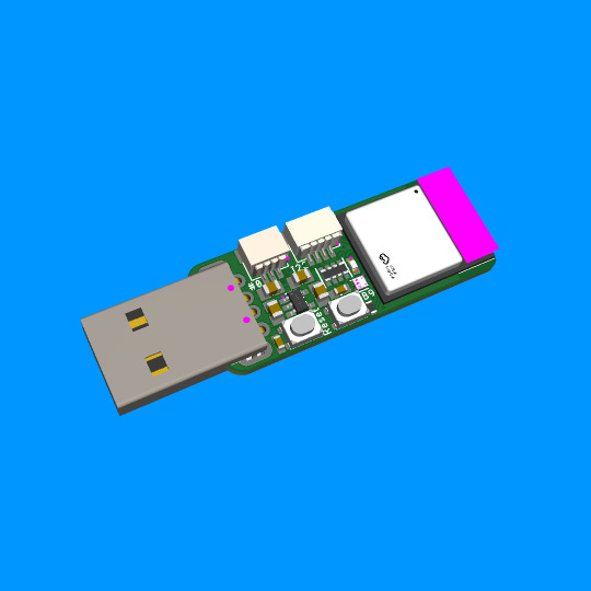
ESP32-C6 Trinkey is a USB Key with Wi-Fi/BLE/ZigBee 🔑🌐🔧
Having wrapped the feather ESP32-C6 (https://github.com/espressif/arduino-esp32/pull/9961) we think it would be neat to have a USB key 'Trinkey' board for the 'C6 because with WiFi+BLE+ZigBee and USB support, this could act as a low-cost gateway or relay board. We kept it simple here: USB type A in, two buttons for resetting and bootloader-select or user input, one red LED, one NeoPixel, Qwiic/Stemma QT I2C port, and a 3-pin JST SH with gpio #0, which can do PWM/ADC/digital in case you want to add another potentiometer, relay, servo or NeoPixels (on the back you can select if you wish to 3V or 5V power). The goal here is to keep it small, cheap, and extensible. We think we did a good job; what do you think?
#adafruit#esp32#arduino#trinkey#usbkey#gateway#relayboard#iot#smarttech#diyproject#microcontroller#pwm#zigbee
6 notes
·
View notes
Text
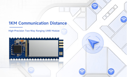
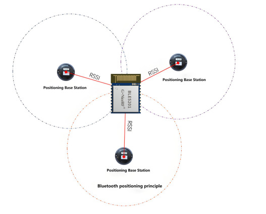
A Comprehensive Comparison of Bluetooth and UWB (Ultra-Wideband) Technologies: A Guide to Precise Positioning
The rapid development of the indoor positioning industry and the quick expansion of the market are closely related to the diversification of positioning technologies. Common indoor positioning technologies include Bluetooth positioning, WiFi positioning, UWB (Ultra-Wideband) positioning, and ZigBee positioning, among others. In recent years, indoor navigation and positioning have become increasingly common, such as in underground parking lot vehicle location, smart guide systems in hospitals and nursing homes, and asset and item tracking in warehouses. Currently, the most common positioning technologies on the market are Bluetooth-based and UWB-based (Ultra-Wideband) technologies. Today, we will mainly introduce the differences between NiceRF's Bluetooth positioning and UWB positioning.
What are the differences between Bluetooth positioning and UWB positioning, and what are the main distinctions?
Supported wireless protocols
Bluetooth positioning is based on the standard Bluetooth 4.0-5.2 protocols
UWB (Ultra-Wideband) positioning uses UWB wireless communication technology, which supports extremely wide bandwidth (typically over 500 MHz). This protocol is designed for high precision and low latency communication, providing reliable performance in complex environments.
UWB3000F27 and UWB3000F00 adhere to IEEE802.15.4-2015 and IEEE802.15.4z (BPRF mode) standards, while UWB650 follows the IEEE 802.15.4-2020 Standard protocol.
Positioning Principles and Accuracy
Bluetooth Positioning: Bluetooth positioning primarily relies on RSSI (Received Signal Strength Indicator) measurements to estimate the distance between devices by measuring signal strength. NiceRF uses more advanced positioning methods, employing Bluetooth Angle of Arrival (AoA) and Angle of Departure (AoD) technologies to enhance positioning accuracy. The accuracy of Bluetooth positioning typically ranges from 1 to 5 meters, depending on the environment, the number of devices, and their configuration.
UWB Positioning: UWB positioning typically uses ToF (Time of Flight) and TDoA (Time Difference of Arrival) measurement principles. It determines distance by accurately measuring the signal propagation time. UWB positioning accuracy can reach within 10 centimeters and, under ideal conditions, can even achieve accuracy of a few centimeters. This high precision makes UWB highly advantageous in applications requiring exact positioning.
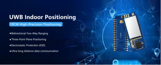
UWB3000F27 and UWB3000F00: These modules are used for two-way long-distance ranging, TDoA (Time Difference of Arrival), and PDoA (Phase Difference of Arrival) systems, with positioning accuracy up to 10 centimeters.
UWB650 Module: This module integrates data communication, double-sided two-way ranging (DS-TWR), and three-point planar positioning functions using UWB technology. It supports communication distances of over 1 KM in open environments, making it suitable for long-distance ranging applications.
Anti-Interference Capability
Bluetooth Positioning: Bluetooth technology operates in the 2.4 GHz frequency band, making it susceptible to interference from other devices such as Wi-Fi and microwave ovens, which can affect positioning accuracy and stability.
NiceRF Bluetooth 5.2 protocol utilizes Silicon Labs' EFR32BG22C224 SOC chip. It features low power consumption, small size, long transmission distance, and strong anti-interference capabilities.
UWB Positioning: UWB technology uses an ultra-wide frequency band, offering strong anti-interference capabilities. It can provide stable positioning services in complex environments and is less likely to be affected by other wireless devices.
Data Transmission Speed
Bluetooth Positioning: Bluetooth Low Energy (BLE) is primarily designed for low power consumption, typically resulting in lower data transmission rates.
UWB Positioning: UWB technology not only provides high-precision positioning but also supports high data transmission rates, making it suitable for applications that require the simultaneous transmission of large amounts of data and precise location tracking.
Synchronization Mechanism
Bluetooth Positioning: Synchronization between Bluetooth devices typically relies on communication between the master and slave devices, which may introduce some time delay.
UWB Positioning: UWB uses a time synchronization mechanism, achieving precise synchronization between devices through high-precision timestamps of ultra-wideband signals.
Deployment Density
Bluetooth Positioning: Due to the accuracy of Bluetooth positioning being significantly affected by signal strength and interference, a high number of Bluetooth beacons (Beacons) are needed to cover the target area. This can lead to high-density deployment, especially in large or complex environments.
UWB Positioning: UWB positioning systems typically require less infrastructure to cover the same area because their high precision and strong anti-interference capabilities can provide stable positioning services over a larger range. This makes UWB systems more cost-effective for large-scale deployments.
Standby Duration
Bluetooth Positioning: A significant advantage of Bluetooth technology is its low power consumption. Devices using BLE can typically operate for extended periods, with standby times reaching several months or even years, making it well-suited for scenarios requiring long-term continuous operation.
UWB Positioning: UWB generally involves high power consumption for ultra-long-distance modules, making it less advantageous in terms of standby duration. UWB modules are better suited for high-precision positioning tasks of shorter duration.
Application Scenarios
Bluetooth Positioning: Widely used in indoor navigation, personnel tracking, asset management, smart homes, and customer behavior analysis in retail stores. This is mainly due to its low cost, low power consumption, and convenient deployment characteristics.
UWB Positioning: Due to its high precision and reliability, UWB is widely used in industrial automation, robotic navigation, drone positioning, sports and medical tracking, and high-precision asset management, among other fields requiring accurate positioning.
How to Choose the Right Indoor Positioning Solution
When choosing an indoor positioning solution, it is recommended to first clarify your positioning needs, including the required indoor positioning accuracy and the functional requirements of the positioning solution. Next, consider the budget you can allocate for the indoor positioning solution and the complexity of setting up the positioning environment.
The need for indoor positioning accuracy
Bluetooth Positioning: Bluetooth positioning accuracy is typically around 3 to 5 meters, making it suitable for applications where high precision is not critical.
UWB Positioning: UWB (Ultra-Wideband) positioning technology can provide centimeter-level accuracy, typically ranging from 10 to 30 centimeters. This high precision makes UWB ideal for applications requiring exact positioning.
Complexity of Setting Up the Positioning Environment:
Bluetooth Positioning: The layout is relatively simple; you just need to pay attention to the spacing between beacons.
UWB Positioning: The layout is more complex compared to Bluetooth positioning because it involves the installation of UWB base stations.
For details, please click:https://www.nicerf.com/products/ Or click:https://nicerf.en.alibaba.com/productlist.html?spm=a2700.shop_index.88.4.1fec2b006JKUsd For consultation, please contact NiceRF (Email: [email protected]).
0 notes
Text
Fabricación casera: El dron M5Stamp Fly ESP32-S3 WiFi se maneja a través del controlador de joystick M5Atom WiFi, empleando la tecnología ESPNOW.
El M5Stack M5Stamp Fly es un dron compacto impulsado por el módulo WiFi ESP32-S3, que incluye un componente IoT M5Stamp S3 que permite conectividad WiFi 4 y Bluetooth Low Energy (BLE). Este dron está equipado con cuatro motores y una amplia gama de sensores, lo que lo convierte en un dispositivo altamente versátil. Los usuarios pueden controlar el M5Stamp Fly a través del M5Atom Joystick, que…
0 notes
Text
Erfahrungsbericht: Wie gut sind die neuen E-Paper Displays von Soldered?
Von der Firma Soldered habe ich zwei E-Paper Displays für dieses Review erhalten. Ein E-Paper Display hat die Vorteile, dass es wenig Strom verbraucht und dabei auch noch von allen Winkeln gut lesbar ist. https://youtu.be/EcERNJUgK_U Disclaimer: Dieser Beitrag enthält eine unabhängige Bewertung der E-Paper Displays von Soldered, die mir kostenfrei zur Verfügung gestellt wurden. Die hier geäußerten Meinungen und Erfahrungen sind meine eigenen und wurden nicht durch Soldered beeinflusst.
Was sind die Vorteile von E-Paper Displays?
E-Paper Displays, auch bekannt als elektronische Papierdisplays, bieten eine Reihe von Vorteilen gegenüber herkömmlichen LCD- oder LED-Displays. Hier sind einige der wichtigsten Vorteile: - Geringer Energieverbrauch: - E-Paper Displays benötigen nur Strom, wenn sich der angezeigte Inhalt ändert. Ein statisches Bild verbraucht keine Energie, was die Batterielebensdauer erheblich verlängert. - Hohe Lesbarkeit bei Sonnenlicht: - E-Paper Displays reflektieren das Licht wie echtes Papier, was bedeutet, dass sie auch bei direkter Sonneneinstrahlung gut lesbar sind. - Augenfreundlichkeit: - Da sie kein Hintergrundlicht verwenden, sind E-Paper Displays weniger anstrengend für die Augen und bieten ein angenehmeres Leseerlebnis, ähnlich wie bei gedrucktem Papier. - Dünn und leicht: - E-Paper Displays sind in der Regel dünn und leicht, was sie ideal für tragbare Geräte wie E-Reader und Smartwatches macht. - Breiter Betrachtungswinkel: - Der Inhalt auf E-Paper Displays bleibt aus nahezu jedem Betrachtungswinkel klar und lesbar, im Gegensatz zu vielen herkömmlichen Displays, die bei seitlichem Blickwinkel verblassen oder verzerrt wirken können. - Flexibilität: - Einige E-Paper Displays können auf flexible Substrate gedruckt werden, wodurch sie für innovative Anwendungen wie gebogene oder faltbare Geräte geeignet sind. - Geringere Lichtverschmutzung: - Da sie ohne Hintergrundbeleuchtung arbeiten, tragen E-Paper Displays weniger zur Lichtverschmutzung bei und sind in dunklen Umgebungen diskreter. Diese Vorteile machen E-Paper Displays besonders attraktiv für Anwendungen, bei denen Energieeffizienz, Lesbarkeit und Augenfreundlichkeit im Vordergrund stehen.
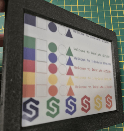
6 Farbiges E-Paper Display von Soldered
Von der Firma Soldered bekommst du ein E-Paper Display mit 6 Farben in der Größe von 6 Zoll (was ca. 15 cm Bildschirmdiagonale entspricht). Es können die Farben schwarz, grün, blau, rot, gelb, orange angezeigt werden. Wenn ein Pixel nicht aktiviert ist, dann wird dieser in Weiß dargestellt, somit kommt man sogar auf 7 Farben.

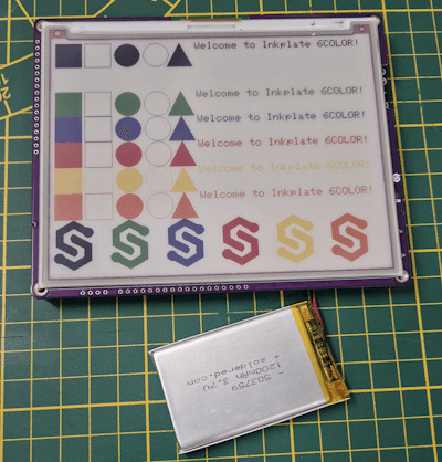
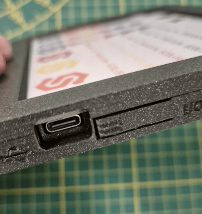
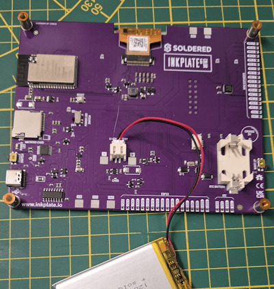
Technische Daten Nachfolgend die technischen Daten des 6 Zoll (ca. 15 cm), 6 Farben E-Paper Display: SchlüsselmerkmaleDetailsDisplaygröße5,85 Zoll (rund 6 Zoll)Auflösung600 x 448 PixelFarbunterstützung7 FarbenBildaktualisierungTeilweise Updates, schnelle InhaltsveränderungMikrocontrollerESP32 mit eingebettetem WiFi und Bluetooth 4.0 (BLE)StromverbrauchSehr gering, 18 µA im Deep-Sleep-ModusStromversorgungLithium-Akku oder USB, integriertes LadegerätSpeicherkartenleserMicroSD KartenleserSchnittstellenZusätzliche GPIO Linien, easyC/Qwiic Kompatibilität, Unterstützung für I²C und SPISoftwareFertige Arduino Bibliothek (100 % kompatibel mit Adafruit GFX) und MicroPythonGehäuseoptionenOptional 3D-gedrucktes GehäuseAkkuoptionenOptional 1200mAh AkkuAbmessungen131,5 x 105,5 x 10 mmAbmessungen mit Gehäuse140 x 119,3 x 13,6 mm Aufbau des E-Paper-Displays Auf der Rückseite des Displays findest du einige Anschlüsse für Sensoren/Aktoren sowie unter anderem das Batteriefach für die Backupbatterie der RTC (RealTimeClock). Einstellungen und dort fügen wir die nachfolgende URL zu den zusätzlichen Boardverwalter URLs ein. https://raw.githubusercontent.com/SolderedElectronics/Dasduino-Board-Definitions-for-Arduino-IDE/master/package_Dasduino_Boards_index.json
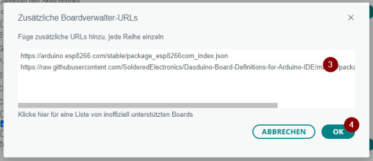
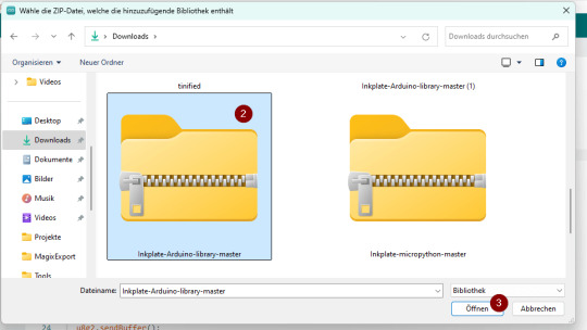
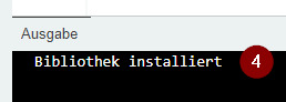
Installieren der Bibliotheken für das Display Der Boardtreiber dient lediglich zum Ansteuern des Mikrocontrollers, damit wir das E-Paper Display ansteuern können, benötigen wir eine zusätzliche Bibliothek, welche wir als ZIP-Datei vom GitHub Repository SolderedElectronics / Inkplate-Arduino-library herunterladen können.

Unterschiede bei der Programmierung von E-Paper Displays von Soldered Beide Display (6 Zoll & 10 Zoll) kannst du sehr einfach über die Arduino IDE programmieren. Der Bibliothek liegen zu jedem Display Beispiele von Einfach bis Komplex bei. Jedoch hat das 10-Zoll-Display ein Feature, welches dem 6 Zoll derzeit fehlt, es ist ein Partial Update. Dieses bewirkt, dass nicht das komplette Display neu geschrieben wird, sondern nur die Daten, welche sich neu im Puffer befinden, somit ist die Anzeige neuer Daten schnell erledigt. Anzeigen von Text & Formen in diversen Farben auf dem Soldered Inkplate 6Color E-Paper Display Zunächst programmieren wir ein kleines Dashboard, welches alle 15 Minuten aktualisiert wird. Auf diesem Dashboard soll nachfolgende Daten angezeigt werden: - die Uhrzeit von der RealTimeClock, - der Status der Webseite http://draeger-it.blog

Das Gute an dem E-Paper Display ist, dass dieses ohne Hintergrundbeleuchtung daher kommt und somit auch nicht so sehr aufträgt, wenn es an der Wand montiert ist. Programm - Dashboard für Status einer WebseiteHerunterladen #include "HTTPClient.h" #include "Inkplate.h" #include "WiFi.h" //Zugangsdaten zum lokalen WiFi Netzwerk const char ssid = ""; const char *password = ""; //Die Webseite welche geprüft werden soll String hostname = "http://draeger-it.blog"; HTTPClient sender; WiFiClient wifiClient; Inkplate display; const int PAUSE = 900000; void setup() { //starten der seriellen Verbindung mit 115200 baud Serial.begin(115200); //Aufbau der WiFi Verbindung WiFi.mode(WIFI_MODE_STA); WiFi.begin(ssid, password); //solange die WiFi Verbindung noch nicht hergestellt wurde, //soll ein Punkt ausgegeben werden while (WiFi.status() != WL_CONNECTED) { delay(500); Serial.print("."); } display.begin(); display.clearDisplay(); display.display(); //Einmaliges setzen der Uhrzeit / des Datums an der RTC. //Dieser Wert wird durch eine Pufferbatterie gehalten! //display.rtcReset(); //display.rtcSetTime(16, 6, 00); //display.rtcSetDate(2, 15, 7, 2024); } //Funktion zum schreiben eines Textes an einer bestimmten Position mit einem Style void setText(String text, int coord_x, int coord_y, int color, int textSize) { display.setTextColor(color); display.setCursor(coord_x, coord_y); display.setTextSize(textSize); display.print(text); } //Prüft ob der Hostname verfügbar ist, also der HTTP-Code gleich 200 ist. bool hostAvailable() { if (sender.begin(wifiClient, hostname)) { int httpCode = sender.GET(); if (httpCode > 0) { Serial.println("httpCode: " + String(httpCode)); return httpCode == 200; } else { Serial.printf("HTTP-Error: ", sender.errorToString(httpCode).c_str()); } } return false; } //liest einen Zeitstempel von der RealTimeClock String readRTC() { display.rtcGetRtcData(); int minutes = display.rtcGetMinute(); int hour = display.rtcGetHour(); int day = display.rtcGetDay(); int weekday = display.rtcGetWeekday(); int month = display.rtcGetMonth(); int year = display.rtcGetYear(); char buffer; sprintf(buffer, "%d/d/d d:d", year, month, day, hour, minutes); Serial.println(buffer); return buffer; } void loop() { //leeren des Displays display.clearDisplay(); display.display(); display.fillScreen(INKPLATE_WHITE); //laden des Logos display.drawImage("https://draeger-it.blog/wp-content/uploads/2024/07/logoSD.bmp", 0, 0, true, false); //schreiben der Überschrift setText("Dashboard", 165, 20, INKPLATE_ORANGE, 3); //schreiben des aktuellen Zeitstempels setText(readRTC(), 165, 50, INKPLATE_GREEN, 2); //zeichnen der Ampel display.drawRoundRect(50, 130, 60, 140, 6, INKPLATE_BLACK); display.drawCircle(80, 170, 20, INKPLATE_BLACK); display.drawCircle(80, 220, 20, INKPLATE_BLACK); //Wenn die Webseite verfügbar ist, dann... if (hostAvailable()) { display.fillCircle(80, 220, 10, INKPLATE_GREEN); setText("Webseite erreichbar!", 120, 215, INKPLATE_GREEN, 2); } else { //Wenn die Webseite NICHT verfügbar ist, dann... display.fillCircle(80, 170, 10, INKPLATE_RED); setText("Webseite nicht erreichbar!", 120, 165, INKPLATE_RED, 2); } //einen Text in den Footerbereich schreiben display.setTextColor(INKPLATE_BLACK); display.setCursor(115, 420); display.setTextSize(1); display.print("Stefan Draeger | https://draeger-it.blog | [email protected]"); display.display(); //einlegen einer Pause von 15 Minuten delay(PAUSE); } Read the full article
0 notes