#CAD Plugins
Explore tagged Tumblr posts
Visit Tumblr Blog
Explore Tumblr blogs with no restrictions, modern design and the best experience.
Last Seen Tumblr Blogs


Fun Fact
Tumblr has 411 employees.
Text
Faster, Smarter Solar PV Design – The Best AutoCAD Plugins
Designing efficient and accurate solar photovoltaic (PV) systems is crucial in today's renewable energy landscape. For professionals in the field, leveraging advanced tools can significantly enhance the design process. AutoCAD, a leading design and drafting software, offers specialized plugins tailored for solar PV design. These plugins streamline complex tasks, ensuring precision and efficiency.
Understanding AutoCAD Plugins for Solar PV Design
AutoCAD plugins are add-on software components that extend the capabilities of the base AutoCAD program. In the context of solar PV design, these plugins introduce features specifically designed to address the unique challenges of planning and implementing solar energy systems. They automate repetitive tasks, provide specialized tools for layout and analysis, and integrate seamlessly with existing workflows.
Key Features of Solar PV Design Plugins
3D Modeling and Visualization: Accurate 3D models of rooftops or terrains are essential for planning solar installations. Plugins like Virto.CAD enable users to create detailed 3D representations, facilitating precise placement of solar modules and assessment of potential shading issues.
Automated Layout Generation: Designing the optimal arrangement of solar panels can be time-consuming. Plugins offer automated tools that generate efficient module layouts based on the available space and desired energy output. This ensures maximum utilization of the area and optimal energy production.
Irradiation and Shadow Simulation: Understanding how sunlight interacts with the installation site throughout the year is vital. Plugins provide simulation tools that model sunlight exposure and predict shading patterns, allowing designers to optimize panel placement and orientation.
Electrical Configuration and String Mapping: Proper electrical design ensures the safety and efficiency of the PV system. Plugins assist in configuring inverters, designing string layouts, and planning cable routes, reducing the risk of errors and ensuring compliance with electrical standards.
Bill of Materials (BOM) Extraction: Accurate documentation of required materials is essential for budgeting and procurement. Plugins can automatically generate BOMs, detailing all components needed for the installation, which streamlines the planning process and ensures all necessary materials are accounted for.
Notable AutoCAD Plugins for Solar PV Design
Virto.CAD: This plugin offers a comprehensive suite of tools tailored for both ground-mounted and rooftop solar projects. Features include 3D roof modeling, module layout automation, irradiation simulation, and integration with other engineering tools like Plex-Earth. Virto.CAD is designed to reduce engineering time significantly, making the design process more efficient.
PV Rocket: Serving as an add-in to AutoCAD, PV Rocket focuses on automating the creation of construction documents for solar projects. It streamlines the design process by providing tools that assist in planning, implementing, and approving solar PV systems, thereby reducing the time and effort required for documentation. pvrocket.com
Benefits of Using AutoCAD Plugins in Solar PV Design
Enhanced Accuracy: Automated tools minimize human errors, ensuring that designs are precise and reliable.
Time Efficiency: Automation of repetitive tasks accelerates the design process, allowing for quicker project turnaround.
Cost Savings: Efficient design processes reduce labor costs and help in identifying the most cost-effective solutions.
Improved Collaboration: Seamless integration with other tools and platforms facilitates better communication and collaboration among project stakeholders.
Choosing the Right Plugin
When selecting an AutoCAD plugin for solar PV design, consider the following factors:
Project Requirements: Assess the specific needs of your project, such as the type of installation (rooftop or ground-mounted), scale, and complexity.
Compatibility: Ensure the plugin is compatible with your version of AutoCAD and any other software tools you use.
User Support and Training: Opt for plugins that offer robust support and training resources to help you maximize their potential.
Cost: Evaluate the pricing structure to ensure it aligns with your budget while meeting your functional requirements.
Conclusion
Integrating specialized AutoCAD plugins into your solar PV design workflow can lead to more accurate, efficient, and cost-effective projects. By automating complex tasks and providing tools tailored to the unique challenges of solar design, these plugins empower professionals to deliver high-quality solutions in the rapidly evolving renewable energy sector.
#Solar Design Tool#Solar PV Design Software#cad plugin for solar#Autocad Solar PV Design#PV Design AutoCAD
0 notes
Note
If you are going to make a game here’s some things that might be helpful!
Game engines:
Godot: very new dev friendly and it’s free. Has its own programming language (GDscript) but also supports C#. It’s best for 2D games but it can do 3D also.
Unity: I don’t even know if I should be recommending Unity. It has caused me much pain and the suffering. But Unity has an incredible amount of guides and tutorials. And once you get the hang of something it’s hard to get caught on the same thing again. It also has a great Visual Studio integration and uses C#. I will warn you the unity animator is where all dreams go to die. It’s a tedious process but you can probably get some plugins to help with that.
Unreal: Don’t use it unless you’re building a very large or very detailed 3D game. It also uses C++ which is hell.
Renpy: Made for visual novels but has support for small mini games. It only supports Python iirc. Basically if you’re making a VN it’s renpy all the way otherwise you should look elsewhere.
What to learn: Game design and how to act as your own game designer. As a designer you need to know if a part of your game isn’t meshing with the rest of it and be willing to give up that part if needed. Also sound design is very important as well. If you want to make your own sounds audacity is perfect for recording and cutting up your clips. If you want to find sound effects I recommend freesound.org and the YouTube royalty free music database.
Sadly I can’t recommend a lot of places to learn this stuff because I’m taking Game Development in Uni. So most of my info comes from my lectures and stuff. One of my game design textbooks is pretty good but it’s around $40 CAD. It’s called the game designers playbook by Samantha Stahlke and Pejman Mirza-Babaei if you’re interested (fun fact there’s a photo of Toriel in there)
Anyway sorry for dumping this large ask on you I’m just really passionate about game design and I like to see other people get into it.
please do not apologize I'd never heard half of this stuff so this is super useful!! I've seen some godot tutorials on YouTube although so far I've played around with RPG maker MV (it was on sale. very very fiddly interface, i had trouble getting around it) and gamemaker, which recently became free for non-commercial use (a lot more approachable on first impact but like i said, haven't really done anything substantial in either yet).
mostly, I'm still in the super vague stage. I've got an idea for the main story conflict, the protagonist and their foil, the general aesthetic i want to go for (likely 2D graphics, but it would be cool to make like. small cutscenes in low-poly 3D) but not much else. haven't exactly decided on the gameplay either! it's gonna necessarily be rpg-esque, but I'm not much of a fan of classic turn-based combat so. I'm gonna check out other games and see if i can frankenstein anything cooler :P
#like for example. if i were ever to make a daemo game (knock on wood) i was thinking that it would work out quite well#if i made it a PUZZLE rpg kind if game. since the player character is no longer frisk/chara/connected to the player#and daemo doesn't really have any reason to 1) be possessed or 2) go on murderous rampages#so with a base game like undertale where those ARE crucial parts of player-world interaction I'd have to redirect it elsewhere#it being player input in the story#but I'm not sure puzzles are quite the solutions for this other story....... we'll see#answered asks#SAVE point#thank you so much!
83 notes
·
View notes
Text
Last Monday of the Week 2025-03-03
Accidentally really only did one thing this past week
Listening: I've been assembling a bunch of music videos so that I can have them on the TV when I just want some visual noise, which has involved watching a lot of music videos. I should really just make this playlist public but: Virtual Insanity by Jamiroquai
youtube
Also this very cute music video for a cover of How Will I Know by Zee Machine who previously features on Tuesday Again.
youtube
Reading: Bad, mostly nothing. Picking at things and putting them down.
Watching: Also very little, half-watched Flow at canmom's animation night but it was both late and I was locked in on some CAD, so I really need to rewatch it sometime.
Making: Lots! Sewing and hemming then ripping and resewing the pillowcase, because I did a fucked bad job. It's going better now.
Also the ongoing saga of the lapboard which is now in a "ready for use, with caveats" state, which is to say that the ergonomics are not perfect and it needs a few tweaks, but it can be used as is. See that at #lapboard on the blog. It has been fun and has really pushed me to learn OnShape better than even the server case project, I'm much faster at it and much more comfortable with the interface now. Picking up some of the shortcuts more seriously and also learning where I can lean on the more advanced features like promoting entities into a sketch and making more convoluted references.
Playing: Literally nothing it's crazy.
Tools and Equipment: I have been using fish shell at work, which I don't think I've pitched it before. It's a very easy to use shell that comes with a lot of features very reliably out of the box, but I want to pitch specifically the fzf plugins for fish
These integrate some very fast fuzzy searchers on top of fish to make it very easy to, say, directly open a file that contains a specific line even in a huge codebase, or to locate a particular commit in a git repo, or just search your enormous command history for the right command without having to tab up and down all day. Well okay that last one is now built into fish but it used to.
Fish is really worth trying if you haven't, it isn't anything like any of the bourne compatible shells but it improves on them in a number of ways in the process.
5 notes
·
View notes
Note
do you have any tips & tricks for how to put vector art on a PCB? any specific tools you use? i ended up having to do a crazy complex mix of KiCAD and EasyEDA and Inkscape with various hacky plugins/extensions, i wish there was something easier to get artwork on PCBs.
for EagleCAD we have a python script that can insert any PNG/BMP as well as any vector font by rasterizing it into the silkscreen layers
https://learn.adafruit.com/adafruit-pinguin-for-eagle-cad
https://github.com/adafruit/Adafruit_Pinguin
however! we’re going to see what we can for a KiCAD guide, we’ll post up on tumblr too!
(and there is also this guide!)
22 notes
·
View notes
Text
bruh I was trying to be so positive but CAD is really not clicking, does anyone know if clipstudio has any decent plugins for accurate 2D dimensioning
#landscape architecture#autocad#clip studio paint#if I have to base a career and practice on vector rendering trick statement I don't think I could do it
4 notes
·
View notes
Text
Hello there, readers! Today, we will talk about another great plugin for SketchUp ? it is called PlusSpec and it is truly a thing of beauty.
PlusSpec was built with mostly residential construction in mind, however, it is quite capable at other types of building work as well. Partnered with RubySketch, PlusSpec is a game-winner in BIM and VDC market. Bring on the architect wars!
What is PlusSpec for SketchUp Pro
The main idea behind PlusSpec is to convert SketchUp into a fully capable Virtual Design and Construction (VDC) app. PlusSpec lets you create constructible designs and get the documentations to build them. It is a magic app that snaps together CAD and BIM, 3D design and 2D documentation, VDC and Estimation altogether!
With an astonishing turn, PlusSpec will allow you to use readily available building material specifications from real manufacturers. This information is available in the form of materials with embedded data, and when you use those materials in SketchUp, you add values automatically to your model.
Read more
2 notes
·
View notes
Text
How to Integrate 3D Map Illustration into Site Analysis for Architectural Projects

Integrate 3D Map Illustration into Site Analysis
In the world of architecture and urban planning, understanding the terrain, infrastructure, and environment is critical before laying the first brick. Traditional site analysis methods have served us well, but as technology advances, so do our tools. One of the most innovative advancements in this space is the use of 3D Map Illustration and 3D Vector Maps in architectural planning.
Combining artistic clarity with technical depth, 3D map illustrations offer more than just visual appeal—they provide actionable insights. Let’s explore how integrating these advanced tools into your Architecture Illustration process can streamline site analysis and improve project outcomes.
What Is a 3D Map Illustration?
Unlike standard 2D maps, these illustrations display terrain, buildings, infrastructure, vegetation, and other features in a three-dimensional space. They give architects, engineers, and planners a much deeper understanding of the site conditions.
Often created using GIS data, CAD software, and digital illustration tools, 3D map illustrations are ideal for both technical analysis and presentation purposes. They are more than just artistic renderings—they’re functional, data-driven visual tools.
Why Use 3D Map Illustrations in Site Analysis?
It includes examining a location’s topography, climate, vegetation, zoning, infrastructure, and accessibility. Here’s why 3D Vector Maps and 3D map illustrations are revolutionizing this process:
1. Enhanced Spatial Understanding
While 2D drawings give flat representations, 3D Map Illustrationprovides a volumetric perspective.
2. Data Integration
Modern 3D vector maps can incorporate real-time data such as topography, utilities, and environmental factors. This integration helps identify potential challenges, like flood zones or unstable terrain, early in the design process.
3. Improved Client Communication
With Architecture Illustration in 3D, clients and community members can easily understand and visualize the proposed development within its context.
4. Better Decision-Making
Using 3D maps during site analysis supports better decision-making. Whether it’s choosing optimal building orientation, identifying natural shade zones, or evaluating how structures impact sightlines, the 3D visualization simplifies complex evaluations.
Step-by-Step: Integrating 3D Map Illustration into Site Analysis
Let’s break down how to incorporate 3D map illustration and 3D Vector Maps into your architectural site analysis workflow.
Step 1: Gather Site Data
Topographical surveys
GIS layers
Aerial imagery
Zoning regulations
Infrastructure maps (roads, utilities, drainage)
Environmental reports
Step 2: Choose the Right Tools and Software
There are many tools available for creating 3D Vector Maps and architectural illustrations. Some of the popular ones include:
SketchUp – Great for quick, interactive 3D models.
Blender or Cinema 4D – For highly stylized 3D illustrations.
Adobe Illustrator (with plugins) – To enhance vector-based output.
Choose a combination that fits both your technical needs and aesthetic style.
Step 3: Create the Base Terrain Model
This forms the physical base upon which other features—roads, buildings, vegetation—will be layered. Many software platforms can convert contour lines and elevation points into 3D surfaces automatically.
Step 4: Add Site Features Using Vector Layers
Now incorporate other elements such as:
Roads and transportation networks
Water bodies and drainage systems
Green zones and vegetation
Existing structures or utilities
These layers, typically drawn as 3D Vector Maps, provide an accurate spatial layout of all critical site components.
Step 5: Apply Architecture Illustration Techniques
This is where artistry meets data. Use Architecture Illustration principles to render the map with aesthetic enhancements:
Textures for terrain (grass, sand, water, urban)
Stylized representations of trees, buildings, and shadows
Labeling of key zones and infrastructure
Lighting effects for better depth perception
Step 6: Use for Analysis and Reporting
Once the map is complete, use it to conduct site analysis:
Determine view corridors and sightlines
Analyze sun paths and shading
Evaluate accessibility and circulation
Review spatial relationships and setbacks
These insights can then be documented in your architectural site report, with visuals that clearly back up your recommendations.
Use Cases: Where 3D Map Illustration Excels
Here are a few examples of how 3D Vector Maps are applied in real architectural projects:
Urban Master Planning
City planners use 3D maps to visualize entire neighborhoods, analyze density, and simulate transportation flows before construction begins.
Resort and Campus Design
When designing large areas like resorts or educational campuses, 3D illustrations help stakeholders understand zoning, amenities, and pedestrian routes.
Landscape Architecture
Landscape architects use 3D map illustration to study the interaction between built environments and nature—perfect for planning gardens, parks, and open spaces.
Infrastructure Projects
Infrastructure projects, like bridges, tunnels, and roads, benefit from 3D visuals to navigate complex terrain and urban constraints.
Integrating 3D Vector Maps in Projects
Here are a few additional benefits of incorporating 3D Vector Maps at the start of your architectural workflow:
Reduces design errors by visualizing constraints early
Accelerates approvals with more convincing presentations
Encourages collaboration across disciplines (engineering, landscaping, urban planning)
Saves cost and time by identifying site issues before they become expensive problems
The Future of Architecture, Illustration and Mapping
We’re heading toward a future where maps aren’t just flat diagrams—they’re immersive, interactive environments.
From drone-based site scans to AR-compatible 3D maps, architectural site analysis is becoming more data-rich and user-friendly. It’s no longer about lines and elevations—it’s about experiences and environments.
Final Thoughts
Incorporating 3D Map Illustration and 3D Vector Maps into your site analysis isn’t just a trend—it’s a game-changer. These tools enhance your technical accuracy, improve communication, and ultimately lead to more successful architectural outcomes.
Whether you’re designing a single home or planning an entire urban district, using modern Architecture Illustration tools helps you see the full picture—literally and figuratively.
So, as you gear up for your next architectural project, make sure your toolkit includes more than just rulers and blueprints.
0 notes
Text
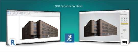
The Bridge to Innovation: Why Revit Needs an OBJ Exporter
Introduction
Autodesk Revit is a powerful BIM (Building Information Modeling) software used extensively in the architecture, engineering, and construction industries. It enables professionals to design, model, and document complex building structures with precision and efficiency. However, there are situations where you may need to export your Revit models to other software applications for various purposes, such as visualization, simulation, or 3D printing. This is where an OBJ (Wavefront Object) exporter for Revit becomes invaluable. In this blog post, we'll explore the reasons why you need an OBJ exporter for Revit and the benefits it brings to your workflow.
1. Compatibility with a Wide Range of 3D Software
One of the primary reasons for using an OBJ exporter for Revit is compatibility. OBJ is a widely recognized 3D file format supported by an extensive list of 3D software applications. When you export your Revit models as OBJ files, you can easily share your designs with collaborators or transfer them to other specialized software for tasks such as rendering, animation, or simulation. Some popular software packages that support OBJ include Blender, 3ds Max, Maya, Unity, and many more.
2. High-Quality Mesh Export
Revit models consist of BIM elements like walls, floors, roofs, and families. These elements are typically represented as parametric objects with detailed information. When exporting to OBJ, Revit converts these parametric objects into polygonal meshes, allowing for a more efficient transfer of geometry. OBJ files maintain the visual fidelity and structural integrity of your design, ensuring that complex architectural details and textures are preserved accurately.
3. Streamlined Visualization
Visualization is a critical aspect of architectural and construction projects. An OBJ exporter for Revit simplifies the process of rendering and visualizing your models in other 3D software. You can import your OBJ files into rendering software like Blender or 3ds Max to create stunning, photorealistic renderings, which are essential for client presentations, project approvals, and marketing materials. OBJ files can also be used in virtual reality (VR) and augmented reality (AR) applications, enhancing your ability to communicate design concepts effectively.
4. Simulation and Analysis
In certain scenarios, you may need to analyze your Revit models for structural integrity, energy efficiency, or other factors. Many simulation and analysis tools, such as finite element analysis (FEA) or computational fluid dynamics (CFD) software, require 3D models in a compatible format. By exporting your Revit models to OBJ, you can seamlessly integrate them into these specialized software packages for in-depth analysis and optimization.
5. 3D Printing
The field of 3D printing has seen rapid growth in recent years, and architects and engineers often use it to create physical prototypes, scale models, or custom building components. OBJ files are widely accepted by 3D printing software and services, making it easy to translate your Revit designs into tangible objects. Whether you're working on an architectural model or a structural component, exporting your Revit model as an OBJ file ensures that it can be easily converted into a 3D-printable format.
6. Cross-Platform Collaboration
Collaboration is key in the AEC (Architecture, Engineering, and Construction) industry. Teams often consist of professionals using various software tools, and seamless data exchange is crucial for project success. An OBJ exporter for Revit facilitates cross-platform collaboration by providing a standardized format that can be imported into different software environments. This compatibility reduces the risk of data loss and ensures that all team members can work with the same model.
Conclusion
In conclusion, an OBJ exporter for Revit is a valuable tool that enhances the versatility and compatibility of your BIM workflow. It enables you to share, visualize, analyze, and produce physical models from your Revit designs with ease. By using OBJ as an intermediary format, you can tap into the full potential of your Revit models, allowing you to collaborate more effectively with colleagues and unlock new possibilities in architecture and construction projects. Whether you're creating stunning visualizations, conducting simulations, or 3D printing prototypes, an OBJ exporter for Revit is a valuable addition to your toolkit.
Get FREE Trial
#OBJ exporter for Revit#Autodesk Revit#3D Software#CAD Plugins#CAD Expoters#CAD Importers#CAD Extensions#CAD Software#3D printing#visualization#BIM (Building Information Modeling) software
0 notes
Text
The Best Tools to Overcome Solar Design Efficiency Issues
Introduce the importance of efficient tools in solar project design. Briefly explain how PV Solar Design Software and AutoCAD plugins are revolutionizing solar system planning and implementation. Mention that the blog will address common user queries with actionable insights.
Headings and Content:
1. What is PV Solar Design Software and How Does It Work?
Define PV Solar Design Software and its core functionalities.
Explain how it helps in planning, simulation, and optimization of solar systems.
Highlight features like shading analysis, energy yield prediction, and financial feasibility studies.
2. Why Use AutoCAD Plugins for Solar Design?
Discuss the role of AutoCAD plugins tailored for solar projects.
Explain how these plugins enable detailed layouts and precise system designs.
Mention integration capabilities with PV Solar Design Software for a seamless workflow.
3. How Do These Tools Improve Efficiency in Solar Projects?
Provide examples of how software and plugins reduce time and errors in design.
Explain the benefits of automation, such as faster calculations and layout optimizations.
Include a case study or example where these tools significantly improved project efficiency.
4. Can PV Design Software Maximize Solar Energy Output?
Discuss how these tools use AI and advanced algorithms for system optimization.
Explain techniques like optimal panel placement and angle adjustments.
Include insights into how software adapts designs to local climatic conditions.
5. What Are the Latest Trends in Solar Design Tools?
Highlight recent advancements such as cloud-based platforms and AI-powered analytics.
Discuss the growing importance of collaboration tools for teams working remotely.
Mention innovations in 3D modeling and augmented reality (AR) for solar design.
6. How to Integrate PV Solar Design Software with AutoCAD?
Provide step-by-step guidance on integrating software with AutoCAD plugins.
Discuss best practices for data transfer and maintaining design accuracy.
Highlight common challenges and how to overcome them.
Conclusion: Summarize the advantages of using PV Solar Design Software and AutoCAD plugins. Emphasize their role in improving efficiency, accuracy, and sustainability in solar projects.
Call-to-Action: Encourage readers to explore the latest tools and resources available at Virto.Solar and AutoCAD Plugin Resources for more insights into solar design software.
#pv design software#solar design and electrical layout cad#cad plugin for solar#Solar PV Design#PV Design Software
0 notes
Text
WebAssembly Explained: Boosting Performance in Modern Web Development

In the fast-evolving world of web development, performance and efficiency are paramount. Developers constantly seek technologies that can improve speed, responsiveness, and overall user experience. One such breakthrough technology gaining momentum is WebAssembly. This powerful tool is transforming the way web applications run by enabling near-native performance on browsers. In this blog, we will explore what WebAssembly is, how it works, and why it is revolutionizing modern web development.
What is WebAssembly?
WebAssembly (Wasm) is a binary instruction format designed as a portable target for compiling high-level languages like C, C++, and Rust, enabling them to run on the web at near-native speed. Unlike traditional JavaScript, which is an interpreted language, WebAssembly is compiled, allowing browsers to execute code faster and more efficiently.
It was developed as a collaborative project by major browser vendors including Google, Mozilla, Microsoft, and Apple, to address the limitations of JavaScript performance and enable more complex applications to run smoothly in browsers.
How Does WebAssembly Work?
WebAssembly works by compiling code written in languages like C or Rust into a compact binary format. This format is then loaded and executed directly by the browser’s virtual machine, bypassing the need for JavaScript interpretation and Just-In-Time (JIT) compilation.
The process typically follows these steps:
Writing Code: Developers write code in languages such as C, C++, or Rust.
Compiling to Wasm: This code is compiled into WebAssembly bytecode using specialized compilers like Emscripten or Rust’s wasm-pack.
Loading in Browser: The WebAssembly module is loaded into the browser via JavaScript.
Execution: The browser executes the WebAssembly code at near-native speed, enabling high-performance web applications.
Because of its compact size and efficient execution, WebAssembly modules download faster and run more efficiently than equivalent JavaScript implementations.
Why WebAssembly is a Game-Changer in Web Development
1. Improved Performance
The primary advantage of WebAssembly is its ability to deliver near-native performance within web browsers. Applications that require intensive computations — such as gaming, video editing, and CAD — benefit tremendously from WebAssembly’s speed improvements.
JavaScript engines have come a long way, but WebAssembly pushes the boundaries further by offering a binary format optimized for fast decoding and execution. This results in smoother and faster applications, even for complex tasks.
2. Language Flexibility
WebAssembly opens web development to languages beyond JavaScript. Developers can leverage their expertise in C, C++, Rust, and other languages to build web applications, broadening the pool of web developers and allowing code reuse from existing native applications.
3. Enhanced Security
WebAssembly runs in a secure, sandboxed environment, similar to JavaScript. This isolation helps protect users by restricting access to the underlying system, reducing vulnerabilities while still allowing powerful features.
4. Interoperability with JavaScript
WebAssembly is designed to complement JavaScript, not replace it. Developers can call WebAssembly functions from JavaScript and vice versa, creating a seamless integration for complex applications where performance-critical modules run in Wasm and the UI and less intensive logic remain in JavaScript.
5. Cross-Browser Compatibility
Supported by all major browsers — Chrome, Firefox, Safari, and Edge — WebAssembly ensures consistent behavior across platforms, helping developers build applications that work everywhere without compatibility concerns.
Real-World Applications of WebAssembly
Gaming: WebAssembly allows complex games to run smoothly in browsers without plugins, supporting rich graphics and real-time interactions.
Video and Image Editing: High-performance tools like photo editors and video processors are leveraging Wasm to handle intensive computations in-browser.
Scientific Simulations: Researchers use WebAssembly for browser-based simulations, providing accessibility without sacrificing performance.
Cryptocurrency Wallets and Blockchain: WebAssembly helps optimize cryptographic calculations, speeding up blockchain-related web apps.
External Source for More Info
For a detailed technical dive and latest updates on WebAssembly, the official WebAssembly.org site is an excellent resource maintained by the working group behind the technology.
Internal Link Suggestion
If you're interested in exploring related cutting-edge web technologies, check out our blog on “The Future of Web Development with Rust and WebAssembly” for an in-depth guide.
How to Get Started with WebAssembly
To start experimenting with WebAssembly, developers can use tools like:
Emscripten: A compiler toolchain for compiling C/C++ code to Wasm.
Rust’s wasm-pack: Helps package Rust code for WebAssembly easily.
AssemblyScript: Allows writing WebAssembly modules using a TypeScript-like language.
These tools streamline the process of creating, compiling, and deploying WebAssembly modules in web projects.
Conclusion
WebAssembly is reshaping the landscape of web development by enabling high-performance applications directly within the browser. Its speed, language flexibility, and compatibility make it a valuable tool for developers aiming to push the boundaries of what’s possible on the web.
As the web continues to evolve, WebAssembly promises to empower developers to build faster, more powerful, and more secure applications, ultimately enhancing user experience across the globe.
0 notes
Text
Blender for Dental Download: A Comprehensive Guide
What is Blender?
Blender for Dental download Blender is a free and open-source 3D creation suite that supports the entirety of the 3D pipeline, including modeling, rigging, animation, simulation, rendering, compositing, and motion tracking. It is widely used by artists, designers, and engineers across multiple industries.
In the context of dentistry, Blender is being adopted by dental technicians, orthodontists, prosthodontists, and dental laboratories for tasks such as:
Designing crowns, bridges, and dentures
Creating orthodontic appliances
Performing digital wax-ups
Surgical guide planning
Model editing and preparation for 3D printing
Why Use Blender for Dental Applications?
1. Cost-Effective
Traditional dental CAD software can be prohibitively expensive. Blender, being free and open-source, eliminates the financial barrier for small practices and individual technicians.
2. Customizable
Blender’s open-source nature means it can be tailored to specific needs. Plugins and add-ons like "Blender for Dental" streamline and adapt Blender for dental workflows, adding custom tools, workflows, and interface layouts specifically designed for dental modeling and applications.
3. High-Quality Output
With Blender, users can produce detailed, high-resolution 3D models that are ready for 3D printing or digital storage. The software supports STL, OBJ, and other common 3D file formats used in dentistry.
4. Versatile Integration
Blender can be integrated with other digital tools and workflows. For example, it can work in conjunction with intraoral scanners, 3D printers, and slicer software such as CHITUBOX download, offering a complete ecosystem for digital dentistry.
Blender for Dental: Specialized Add-Ons
The standard Blender software is incredibly powerful, but when tailored for dentistry, its capabilities grow exponentially. Several add-ons and plugins have been developed to convert Blender into a specialized dental tool.
Notable Add-ons Include:
Blender for Dental: A commercial add-on that transforms Blender into a full-fledged dental CAD system. It includes features for crown and bridge design, aligners, splints, and model editing.
OrthoFlow: Focuses on orthodontic applications. Offers tools for bracket placement, arch wire simulation, and more.
Dental Shaper: Helps with morphing and sculpting tools for precise anatomical shaping.
Tips for Success with Blender for Dental
Start with Tutorials: Blender has a steeper learning curve, but there are plenty of dental-specific tutorials available.
Practice Regularly: The more time you spend, the more intuitive it becomes.
Join Communities: Facebook groups, Reddit forums, and Discord servers focused on digital dentistry can be very helpful.
Back-Up Work Regularly: Ensure your work is saved frequently, especially when handling complex cases.
Use Cases and Real-World Applications
Dental Labs: Design restorations digitally and reduce turnaround times.
Orthodontic Clinics: Create aligners and retainer designs in-house.
Academic Institutions: Teach dental students digital workflows without expensive software.
Research and Innovation: Use for bio-modelling, simulations, and custom appliance prototyping.
Final Thoughts
Blender for Dental represents a democratization of dental CAD tools. By using open-source software and cost-effective add-ons, dental professionals can now access powerful digital tools that were once restricted to large practices with significant budgets.
Whether you are a dental technician, clinician, or educator, exploring the Blender for Dental download could be a transformative step for your digital dentistry capabilities. Coupled with slicer software like CHITUBOX download, it opens the door to a complete digital workflow from scan to print.
0 notes
Text
Learning Blender.
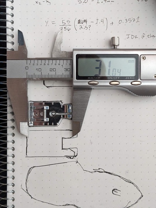
Progress is slow with trying to learn Blender, as I'm not using any tutorials. Currently I've learned how to extrude and dissolve faces, which although it isn't the easiest way to go about things, allows me to work on the case design in my own time instead of relying on somebody else to do it. While learning blender I found some 3D models of the components I use to create slimes, specifically JST pin plugs (both 2 pin and 6 pin), Weimos D1 Mini and a TP4046 model.
I've used these models to use Blender as a sort of piece of CAD software, using this plugin to take the model of my PCB from KiCAD (where the PCB was designed) and put it into blender, although it didn't work. Instead I found a plugin for blender that allowed me to import .step models, which is how I got all of these models inside of blender, now letting me have a fully size accurate 3D model where I can work on fitting the pieces into place well enough. To help with this I got the measurements of the battery I've been using, using a cube to represent it and making the cube slightly larger to give the battery some wiggle room.
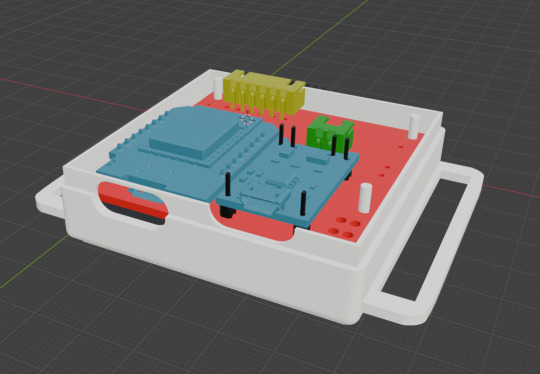
Here is the example of it in blender, it shows how the holes for any component that requires a pin do not line up with the size of the pins, which is what I learned when building my first prototype. I am tempted to learn PCB design in KiCAD now, as I would love to edit the design of this PCB to improve the layout a ton more.
1 note
·
View note
Text
Discover ALCAD: the smart AutoCAD substitute for design professionals
Are you looking for a cost-effective and powerful solution that rivals AutoCAD but with added flexibility and affordability? Look no further than ALCAD, a professional-grade CAD platform that is fast becoming the go-to AutoCAD substitute for architects, engineers, and MEP specialists. ALCAD offers all the features you need, without the high costs and steep learning curve.
Autocad substitute - seamless DWG Compatibility
ALCAD offers seamless DWG compatibility, meaning professionals can work directly with their existing files without worrying about conversions. The user-friendly interface mirrors that of AutoCAD, featuring essential tools such as Layer Manager and XREF Manager, making it easy to transition from AutoCAD to ALCAD. You can quickly adapt to the system and maintain your productivity without a steep learning curve.

Specialized MEP/HVAC Plugins for Advanced Modeling
One of the standout features of ALCAD is its specialized MEP/HVAC plugins, which make it a perfect AutoCAD substitute for MEP professionals. These plugins allow users to model complex systems like plumbing, heating, ventilation, and electrical layouts in both 2D and 3D with great precision. By automating tasks such as material list generation, ALCAD greatly enhances workflow efficiency and accuracy in MEP designs.
ALCAD not only provides powerful CAD tools but also offers affordable licensing models. Whether you need a permanent license or prefer an annual subscription, ALCAD ensures that your CAD software is both cost-effective and reliable, offering an excellent alternative to traditional platforms like AutoCAD.
Conclusion
If you're looking for a cost-effective AutoCAD substitute that doesn’t compromise on features, ALCAD is the perfect solution. With its intuitive interface, DWG compatibility, and specialized MEP plugins, ALCAD delivers everything professionals need to elevate their designs without the high price tag of traditional CAD software. Make the smart choice today and explore ALCAD’s features!
1 note
·
View note
Text
Top 10 Free AutoCAD Alternatives You Should Try in 2025
Looking for cost-effective design software? Discover the Top 10 Free AutoCAD Alternative You Should Try in 2025. These tools offer powerful features for 2D drafting, 3D modeling, and architectural design without the hefty price tag. From open-source favorites like LibreCAD and FreeCAD to web-based solutions like TinkerCAD and SketchUp Free, these alternatives cater to beginners, professionals, and small businesses alike. With intuitive interfaces and robust capabilities, you can create professional-quality designs while saving money. Whether you're an architect, engineer, or designer, these top free AutoCAD alternatives are worth exploring for your next project.
Why Choose a Free AutoCAD Alternative?
AutoCAD is a powerful tool for design professionals, but its cost can be prohibitive for many users. Free AutoCAD alternatives provide affordable solutions without sacrificing essential functionality. These alternatives are ideal for students, small businesses, and independent professionals who need reliable CAD tools for drafting and modeling without incurring high expenses. With advancements in open-source and free software, these tools offer robust features and flexibility, making them a practical choice.
Top Free AutoCAD Alternatives for 2D Drafting
For 2D drafting, tools like LibreCAD and QCAD are excellent choices. LibreCAD is an open-source platform that specializes in 2D design and supports formats like DXF, making it a strong competitor to AutoCAD. Similarly, QCAD offers an intuitive interface and a wide range of drafting features, suitable for creating floor plans, blueprints, and technical diagrams. Both are lightweight and perfect for professionals and hobbyists focused on 2D design.
Free AutoCAD Alternatives for 3D Modeling
When it comes to 3D modeling, FreeCAD and Blender stand out. FreeCAD is a parametric modeling software that allows precise design adjustments and supports engineering workflows. Meanwhile, Blender, though primarily used for animation, includes powerful 3D modeling tools suitable for architectural visualization and detailed designs. These alternatives offer advanced features for creating complex models without the financial investment required for AutoCAD.
Open-Source Free AutoCAD Alternatives
Open-source CAD tools like FreeCAD and LibreCAD offer unmatched flexibility and customization. These programs are continually improved by active online communities, providing users with access to plugins, extensions, and collaborative resources. Open-source software also eliminates licensing restrictions, allowing users to tailor the tools to meet their specific project requirements, making them versatile and budget-friendly options for designers and engineers.
Web-Based Free AutoCAD Alternatives for Accessibility
Web-based CAD tools like TinkerCAD and SketchUp Free provide easy access for users who prefer not to install software. These tools are ideal for beginners and quick projects, offering intuitive interfaces and basic design capabilities. TinkerCAD is perfect for 3D printing and simple modeling, while SketchUp Free allows architects and designers to create 3D structures with ease. Their cloud-based functionality ensures access from any device, making them convenient for on-the-go work.
Comparing Features of Free AutoCAD Alternatives
Free AutoCAD alternatives vary in features, but many offer comparable capabilities for drafting and modeling. For instance, LibreCAD is focused on precision 2D design, while FreeCAD excels in parametric 3D modeling. However, these tools may have limitations, such as reduced support for proprietary file formats like DWG. Despite these minor drawbacks, most free alternatives provide sufficient functionality for small to medium-scale projects, making them viable substitutes for AutoCAD.
How to Choose the Right Free AutoCAD Alternative?
Selecting the best free autocad alternative depends on your specific needs. If you’re working on detailed 2D designs, LibreCAD or QCAD might be the perfect choice. For more intricate 3D modeling, FreeCAD or Blender could meet your requirements. Beginners or casual users may find web-based tools like TinkerCAD and SketchUp Free to be intuitive and user-friendly. Consider factors such as software compatibility, learning curve, and community support when making your decision.
Conclusion
Free AutoCAD alternatives have transformed the CAD landscape, offering powerful tools for professionals and beginners alike. From open-source programs like LibreCAD and FreeCAD to accessible web-based options like TinkerCAD and SketchUp Free, there’s something for everyone. These tools help architects, engineers, and designers create professional-quality work while saving costs. While they may not include every feature found in AutoCAD, they provide more than enough functionality for most design tasks. By assessing your needs and exploring these alternatives, you can achieve exceptional results without breaking the bank.
0 notes
Text
Custom Bins with CaDoodle
This tutorial assumes a basic familiarity with Zack Freedman's Gridfinity system and no familiarity with CAD software. Here's what you'll need:
Inkscape is a Free And Open Source vector illustration program. Vectors aren't really images themselves so much as a running list of defined points and lines on a coordinate plane that a computer can then display as an image. Because these are simply points on a plane, digital vector images can scale infinitely. These points also map to physical
CaDoodle is a Free And Open Source CAD program loosely based on Autodesk's tinkerCAD. Using boolean operations, you can build out basic shapes. CaDoodle can also use OpenSCAD plugins, and has the Gridfinity plugin available to use out of the box.
Start by tracing the objects you want in the orientation you want onto a piece of paper, keeping your pencil as straight as possible (I've used a pen for this entire process so that you can actually see it, but you really should use a pencil). If you have a flat bed scanner, simply put your object on the scanner. This will give you a far more accurate shape to work with and skip the scaling process.
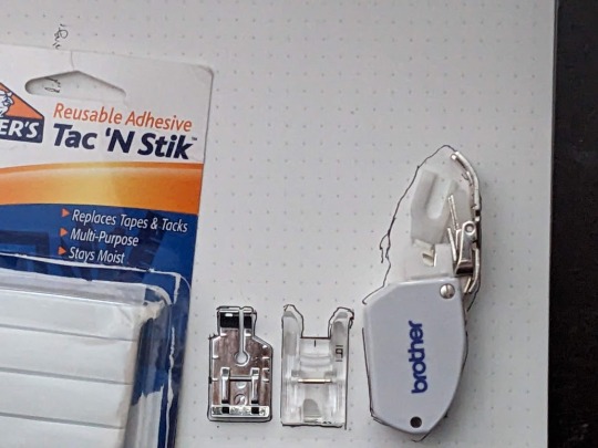
You may find that a little sticky tack to hold each object in place will help. For the two smaller presser feet, I've tried to get as close as possible to the edges. The walking foot, however, has a moving arm that feels so delicate and I don't want to mess it up so I just got the general shape.
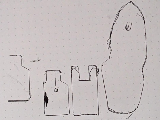
I also marked the hole in the center of the small foot on the far left, and I marked where that arm sits on the presser foot. I then removed the feet from the paper and went over the messier lines, refining them a bit into something neater. After that, I held my phone as level as I could and photographed the tracings. The dots on my paper are 5mm apart, so I can use that to scale the photo later.
I also made sure to take a BUNCH of reference photos with calipers for every object.
Next, it's time to load up Inkscape. I paste my photo of my traced lines into inkscape and use the Measure tool (M) to check on those dots

They're about 15mm apart, so the photo needs to be shrunk to 33.33% of its original size to get them down to 5mm apart. Use the Selection tool (S) and click on the photo. Then, at the top of the screen, you'll have some controls for altering the size of this object.

Changing the units from "mm" to "%" will have you working in percentages. Making sure the padlock icon between the W and the H numbers is closed will ensure that the whole picture scales evenly at the same time. Then enter 33.33%, and press enter. After this, I'm able to check the distance between dots both horizontally and vertically at all four corners of the image and confirm that it's scaled properly. If you used a flatbed scanner, you'll be able to skip this step. Next, select the Pen tool (B) on your keyboard and begin tracing one object.

Click on corners to pivot. Cut off rounded edges with a straight line, as we're going to go back and curve them after the shape is closed. Once you're done, you can select the Node tool (N) to refine the shape. Dragging individual nodes moves them, while clicking and dragging on lines will cause them to curve.
After your tracing looks the way you want it, go to Edit>Preferences>Behavior>Steps and change the "Inset/Outset by" setting to 0.5mm:

Close this window and select your shape. Then, go Path>Outset. This expands the entire path by half a millimeter so your object has some wiggle room. This step is optional, of course, and some people prefer the aesthetic look of a perfect fit, but for your first bins this will increase the chances of your finished product being usable.

At this point you can continue tracing other shapes on the same document if you wish. MAKE SURE YOU SAVE your file as an .SVG as you go.
Next, open CaDoodle. At this point I recommend that you create a fresh CaDoodle document by clicking on the CaDoodle logo in the upper left corner and selecting "New Doodle." Next, click the "Import" button in the upper right corner and select your .svg file that you made in Inkscape. CaDoodle will then load up all your shapes for you, each of which can be moved around independently. They'll even keep whatever colors you were using in Inkscape!

The objects we're working with represent holes. You don't want the recess your object sits in to encompass it completely, because you won't be able to get it out again easily. Set each object's thickness to match the thickness of the object you're storing, minus about 5 to 10 millimeters, by clicking on the height node at the center of the object and either dragging, or manually entering a number.

Then, generate a Gridfinity bin. In the right-hand pane, choose "OpenSCAD_Plugins" from the drop-down, and click on the Gridfinity bin to drop one into your document. A default bin will then generate.

You have tons of options here but we're just going to use the default bin for simplicity-- 42x42x42mm, with no dividers.
Next, select your shape. Right now this shape is a solid that will be printed as-is, and that's useless to us. Click on the "hole" property to turn it into a negative we can cut out of the bin.

Next, either press C on the keyboard or click the magnet icon in the upper right to activate Cruise. This will let you place your shape directly on top of the surface of the bin.
Next, select the black cone icon above the Z axis node. This value should be equal to the height of your gridfinity bin (so 42mm for 6 z-axis units, or in my case 14mm for 2 z-axis units).

Subtract the thickness of your object from this number to sink it into the bin. Mine was 5mm thick, so I want this value to be 37

Finally, with your object still selected, hold down shift and click on the bin. Then, click on the "GROUP" button in the upper right corner, or simply press "G" on the keyboard.

And that's it. This bin is ready to export as an .stl

You can also use the basic shapes in CaDoodle to add finger holes or create recesses for less specific objects. For example, a short cylinder on its side is all I need for a spool of thread, and will serve my purposes better than a custom shape.
0 notes
Text
Twinmotion helps to create gorgeous high-resolution stills. In addition, this software helps to create high-quality videos and provides real-time experiences for the users. Twinmotion helps to support the files for Building Information modelling software, CAD, and modelling solutions. This software also offers direct one-click synchronization with many of the other software which helps to take the design project to the next level.
A wide range of plugins has been offered by Twinmotion which helps to streamline the design workflow. These Twinmotion plugins include:
CityEngine Plugin
This plugin is used to enable the users to preserve the materials, geometry and metadata of the 3D models and to import those 3D scenes into the Unreal engine. The import of the 3D models has been done with minimal loss of quality through this Twinmotion plugin. CityEngine scenes can be imported into Datasmith file format which allows the preservation of complex and large-scale CityEngine scenes.
Form-Z Plugin
This plugin makes it easy to export the project to Twinmotion software. In this plugin, users can synchronize their project with a Direct Link. In this regard, the changes made by the users can be reflected in the Twinmotion software immediately.
Twinmotion Direct Link
Twinmotion Direct Link plugin allows the users to synchronize BIM information as well as geometry from SketchUp Pro to Twinmotion with just a single click.
Navisworks Plugin
The Navisworks plugin of Twinmotion enables the users to import entire scenes from this plugin. These plugins are also used for Unreal Engine. In the case of downloading the latest plugins from the page of Unreal Engine, the reinstallation of those plugins for Twinmotion is not required.
Read more
0 notes