#DWDM topology
Explore tagged Tumblr posts
Visit Tumblr Blog
Explore Tumblr blogs with no restrictions, modern design and the best experience.
Last Seen Tumblr Blogs


Fun Fact
If you dial 1-866-584-6757, you can leave an audio post for your followers.
Text
Operating a Dark Fiber Network: Use Cases, Complexity, Cost vs. Lit Fiber

Are you afraid of the dark? There’s no need because Lightyear’s here to shine a light on dark- fiber network connectivity.
If you’re investigating high-speed fiber options and looking for greater bandwidth and lower latency to improve the performance of your applications and services, then dark fiber or lit fiber could be the silver bullet. In this post, we’ll help you think through considerations on when to go with dark fiber.
What Is Dark Fiber?
Fiber-optic cables carry pulses of light which communicate data. So, if you’re procuring a dark-fiber line, you’re basically looking to rent an unused (or “dark”) set of fiber lines, without any of the additional transmitters usually included. To use technical parlance (according to the OSI model used to describe telecoms infrastructure), dark fiber is an unlit, layer-1 service.
Lit fiber is an adjacent service to dark fiber. With a lit-fiber service, the customer rents a dedicated fiber line, along with all the transmission equipment, from the service provider (billing for lit fiber services is also slightly different, with the cost increasing depending on tiered bandwidth usage).
At this point, you might be wondering why there’s all this fiber lying around unused, anyway? Surely, it’s expensive to lay this stuff in the first place?
It’s a valid question, and there are two main reasons.
Technological improvements. When the Incumbent Local Exchange Carriers (ILECs) first started laying down fiber, back in the late 80s/early 90s, a single fiber channel could transmit data at around 2.5 Gbps. Then the lab geeks figured out they could use Dense Wavelength Division Multiplexing (DWDM) to send multiple data streams down a single channel. Multiple streams = more bandwidth. How much more? Well, you can squeeze 32 Tbs down one channel now, which is about 12,800 times more data. So, modern fiber-optic usage leaves plenty of spare fiber for everyone.
Long-term planners laid extra capacity to save on future costs. Labor and project management makes up much of the cost of a fiber install. Those crazy 20th century ILECs figured they’d save a few bucks and installed additional fiber, far more than their requirements at the time – not anticipating the huge efficiencies DWDM would bring.
So, what’s the net result of these two factors? Depending on your geographic location, there could be plenty of dark fiber going unused that your service provider would be more than happy to lease to you.
Who Uses Dark Fiber?
Lots of folk. We’ve seen dark fiber deployed in many ways by a range of businesses who tend to have the following things in common.
Multiple, well-established static locations
A qualified team of in-house transport technicians capable of lighting a fiber network
A strong need for a secure, low latency network, with scalable network connections
These are some common users of dark-fiber networks.
Wireless Internet Service Providers (WISPs). Cellular providers often use a dark-fiber network to connect their cell towers to the data center. They’ll install and manage their own Dense Wavelength Division Multiplexing (DWDM) equipment, configured either as a point-to-point service or as an any-to-any topology, to best suit local requirements.
Municipalities. Critical infrastructure such as police stations, fire departments, and hospitals needs to be connected with as much security, reliability, and permanence as possible, making dark-fiber networks a great fit for public services.
Schools and colleges. Large, multi-campus institutions like to connect their locations securely, and enjoy the level of control a dark-fiber network provides.
Connecting two data centers. More of a business need than a use case or typical user – we’re often contacted by companies that, for one reason or another, want dark fiber to run between their data centers. Again, as a secure, predictable low-latency solution, it’s a useful addition to a wide area network (WAN).
Where Can I Get Dark Fiber?
The nearer your location to a major city, the greater the chance that dark-fiber services are available to you. There are fiber lines running between the major cities, too.Outside of major cities and their connective infrastructure, it becomes trickier for carriers to make a business case for fiber installations. As we mentioned previously, the CapEx and project management costs make it harder to recoup fiber network investment from major population centers.
Even if your location is close to a major fiber line, it’s by no means a given that you can tap directly into their line to build your dark-fiber network. Connections to a fiber line are made via splice points – and most carriers have no desire to create additional splices on the line.
Once you know where the splice points are, you can work out whether a service provider is able to offer you a fiber buildout to your locations. Think of splice points as highway onramps – even though your house might be underneath the flyover, you could still have several miles to drive before you can merge onto the highway.
To determine whether a service provider is able to offer you dark fiber, you’d work with the same set of culprits you’d deal with for lit fiber service (Zayo, Crown Castle, Lumen, and the like) and go through similar bidding processes (sounds fun, right?).
What Kind of Contracts Are Available for Dark Fiber?
If you find a carrier that owns fiber between the locations you’re looking to connect, the most common kind of dark-fiber agreement is an Indefeasible Right of Use (IRU) lease. These are usually long-term leases – typically between 20 and 30 years.
If that’s more of a bind than you’re looking for, it’s worth investigating whether potential vendors would be willing to offer an International Private Leased Circuit (IPLC). As the name suggests, IPLCs are designed for international networks, and offer shorter terms – some IPLCs even offer monthly rolling contracts.
One disadvantage of IPLCs, however, is the prohibition of subletting – you can’t rent the dark fiber out as if it was your own, which removes the possibility of offsetting the costs of your network.
If you’re looking for a lit-fiber deal, with leased fiber transmitters providing DWDM services, a term length of between three and five years is more commonplace. The costs involved for the provider are subject to change over time, so it makes more financial sense for them to ensure they can adjust equipment rental costs at more regular intervals.
Which Should I Choose – Dark Fiber or Lit Fiber?
When it comes to performance metrics, there’s little difference between these two dedicated internet services. The factors to be considered are scalability, security, and cost.
Scalability. Dark fiber isn’t infinitely scalable, due to the physics involved and the mounting cost of equipment, but it's not that far off! Also, any upgrades you carry out on your existing bandwidth capabilities are entirely your own business – no need to contact the carrier, and there are no additional monthly costs.
Lit fiber upgrades will require some negotiation with the service provider, who is likely to charge you a tiered rate according to your bandwidth requirements.
Security. Neither dark fiber nor lit fiber services provide any visibility into traffic through that part of the network – any security provision must take place after the fiber hands off to the customer premises equipment (CPE).
Cost. When comparing like-for-like network locations and provision, lit-fiber services are generally more expensive. The provider is obviously going to charge more for their leased equipment and technicians than you’d pay if you were procuring these things in-house.
However, the relatively lower cost of dark fiber is only available for customers with considerable connectivity needs – you’ll need to have fairly hefty throughput requirements to justify the outlay, although there’s often wildly unpredictable regional variations in how much providers charge for dark fiber. To run a dark fiber network, you'll need to invest in hardware as well as smart hands to run your network and deal with issues, so there is a breakeven bandwidth point where this makes sense.
Subletting fibers on your dark-fiber network can be a handy way to offset the expense of this long-term investment – although this comes with its own set of legal and contractual hassles and responsibilities with which not every business is prepared to engage.
There are several other variables to consider when gauging dark-fiber costs. These include distance from the fiber splice point, and the links used to reach the fiber line, as well as the distance between your connected locations.
This last cost can quickly mount up, depending on the range of your transmitters – should your transmitter only be effective for up to 500 miles, and your locations are several thousand miles apart, then you’ll need to install and maintain repeaters every 500 miles, increasing your project management and labor costs.
While this list of pros and cons will help you get a sense of what both these services can offer, it might not be so simple to apply this knowledge to the complexities of your business and connectivity procurement needs.
The Lightyear telecom operating system is designed to solve problems like these. With ease, you can configure a dark fiber or lit fiber network and compare options digitally, or arrange a real-time meeting to discuss your options with an experienced industry professional.
0 notes
Text
DWDM Topology Design: How to Make it Right?
Network expansion spurs the demand for faster data transmission and higher capacity over the network. In this case, DWDM emerges as a cost-effective solution to handle these issues, working efficiently to combine multiple wavelengths together and sent them over one single fiber. With the ability to carry up to 140 channels theoretically, higher capacity can be achieved by DWDM technology. This article guides you through some basics of DWDM topology.
Common DWDM Topology Overview
DWDM networks are grouped into four major topological configurations: DWDM point-to-point with or without add-drop multiplexing network, fully connected mesh network, star network, and DWDM ring network with OADM nodes and a hub. The requirements of each DWDM topology differ, and based on various application, it may involve different optical components. Besides these four common DWDM topology, there also exists hybrid network topology, consisting of stars and/or rings that are interconnected with point-to-point links.
Configurations of DWDM Topology
This section illustrates the four basic DWDM topology configurations, help to understand the major differences and applications of them.
Point-To-Point Topology
Point-to-point topology is typically found in long-haul transport, which demands for ultra high speed (10-40Gb/s), ultra high aggregate bandwidth, high signal integrity, great reliability, and fast path restoration capability. The transmitter and receiver within this DWDM topology can be several hundred kilometers away, and the number of amplifiers between the two end points is generally less than 10. Together with add-drop multiplexing, point-to-point DWDM topology enables the system to drop and add channels along its path. A DWDM point-to-point system includes lasers, an optical multiplexer and demultiplexer, fibers, optical amplifiers, and an optical add-drop multiplexer.

Ring-Configuration Mesh and Star Networks
Basically, a DWDM ring network includes a fiber in a ring configuration that fully interconnects nodes. Two fiber rings are even presented in some systems for network protection. This ring DWDM topology is commonly adopted in a local or a metropolitan area which can span a few tens of kilometers. Many wavelength channels and nodes may be involved in DWDM ring system. One of the nodes in the ring is a hub station where all wavelengths are sourced, terminated, and managed, connectivity with other networks takes place at this hub station. Each node and the hub have optical add-drop multiplexers (OADM) to drop off and add one or more designated wavelength channels. As the number of OADMs increases, signal loss occurs and optical amplifier is needed here.

In the ring DWDM topology, a hub station works to manage channel assignment so that a fully connected network of nodes with OADM is accomplished. The hub also makes it possible to connect other networks. A DWDM mux/demux can be connected to an OADM node to multiplex several data sources. The following picture demonstrates a simple DWDM ring topology with a hub and two nodes (A and B).

Transmit and Receive Directions of DWDM Hub
In the previous part, we’ve mentioned DWDM hub, which serves as a very essential parts in a DWDM system. Here we further explain the transmit and receive direction of a DWDM hub, proving system solutions for your reference.
Transmit Direction
A DWDM hub accepts various electrical payloads, such as communications transport protoco/Internet Protocol (TCP/IP), asynchronous transfer mode (ATM), STM, and high-speed Ethernet (l Gb/s, 10 Gb/s). Each traffic type (channel) is sent to its corresponding physical interface, where a wavelength is assigned and is modulated at the electrical-to-optical converter. The optically modulated signals from each source are then optically multiplexed and launched into the fiber.

Receive Direction
When a hub receives a WDM signal, it optically demultiplexes it to its component wavelengths (channels) and converts each optically modulated signal to a digital electrical signal. Each digital signal then is routed to its corresponding electrical interface: TCPIIP, ATM, STM, and so on However, that each channel requires its own clock recovery circuitry because all channels may be at different bit rates.

Conclusion
The network topology of your DWDM system depends on various factors, including the number of nodes, maximum traffic capacity, scalability, number of fiber links between nodes and so on. Attentions also should be attached to the network components involved in the DWDM system. Hope this article could help to get more understanding towards DWDM technology.
Source: http://www.fiber-optic-solutions.com/dwdm-topology-design-make-right.html
0 notes
Text
CWDM: What You Need to Know
Wavelength division multiplexing (WDM) is a technology for transporting large amounts of data between sites. It increases bandwidth by allowing different data streams to be sent simultaneously over a single optical fiber network. There are two main types of WDM systems: coarse wavelength division multiplexing (CWDM) and dense wavelength division multiplexing (DWDM). This article provides some knowledge about CWDM.

What is CWDM?
Coarse Wavelength Division Multiplexing (CWDM) is a wavelength multiplexing technology for cities and access networks. The word coarse means the wavelength spacing between channels is relatively large. Furthermore, CWDM is an ideal solution for short-range applications and is used to improve the transmission capacity of optical fiber and the utilization of optical fiber resources.

CWDM Operating Principle
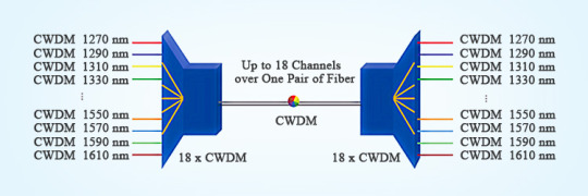
CWDM was standardized by the ITU-T G.694.2 based on a grid or wavelength separation of 20 nm in the range of 1270-1610 nm. It can carry up to 18 CWDM wavelengths over one pair of fibers. Each signal is assigned to a different wavelength of light. Each wavelength does not affect another wavelength, so the signals do not interfere. Each channel is usually transparent to the speed and data, so the voice, video, and other services can be transported simultaneously over a single fiber or fiber pair.
CWDM Network Component
A multiplexer (Mux) combines multiple wavelength channels on a single fiber, and a demultiplexer (Demux) separates them again at the other end. A Mux/Demux set-up is used to increase the end-to-end capacity of a deployed fiber. The Mux is located in the central office, and the Demux is located in the cabinet or splice closure from which the fibers go to their destination in a star-shaped topology.

Features and Benefits
CWDM provides low insertion loss, low polarization-dependent loss, low cost, low-temperature sensitivity, low power consumption, high channel isolation, high data rate, high stability, high reliability, small size, and ease of installation and deployment.
Applications
CWDM is used in metropolitan area networks (MAN), local area networks (LAN), storage area networks (SAN),10-gigabit ethernet, passive optical networks (PON), WDM transmission systems, FTTx networks, 5G front-haul, data centers, online monitoring, fiber optic amplifier, etc.

Conclusion
CWDM has become the preferred solution for increasing the bandwidth of metro/regional and optical access networks. And it has proven to be sufficiently robust, low-cost, and reliable for upgrading the optical network to accommodate future growth. Sun Telecom specializes in providing one-stop total fiber optic solutions for all fiber optic application industries worldwide. Contact us if any needs.
1 note
·
View note
Text
How to Realize Long Distance 40G Network With DWDM Solution
Nowadays, many customers are in need of better data storage capacity and long distance transmission. Faced with this phenomenon, FS has developed DWDM series products such as DWDM Mux, OADM, OEO and so on. And FS is always committed to meeting the specific needs of our customers and providing customized DWDM solutions for them. Currently, one of our customers from the NineStar Connect company is faced with a problem of long distance data transmission and asks FS for help. Let’s see how FS company tackles this problem with DWDM solution.
Background
As mentioned above, this customer is seeking for solution for longer distance transmission. This customer wants to realize 48km transmission, while the maximum transmission distance of 40G QSFP+ optics is limited to 40 km and each 40G interface requires a dedicated fiber between sites. Besides, this customer told FS that their network has a dark fiber linking two sites beyond 40km, but they don’t know the link loss between these sites. Faced with this problem put forward by the customer, FS has designed a DWDM solution to meet this specific need. In the following part, detailed information about this solution will be elaborated.
What Is This DWDM Solution?

From the above topology, we can see that one 40G SR4 QSFP+ transceiver installed on the 40G switch is connected with four 10G SR transceivers by MTP-LC harness cables. So one 40G optical signal can be divided into four 10G signals in this way. In the next step, 10G DWDM SFP+ transceivers on the OEO repeater will be connected with DWDM Mux/Demux for wavelength division multiplexing. And then the optical power will be lowered by using optical attenuator. And the dispersion will be compensated by DCM. When this process is finished, the booster amplifier (BA) will improve the optical power and extend the transmission distance. In the next step, we need to amplify the signal by using pre-amplifier (PA) and then OEO converts the signal to the corresponding DWDM wavelengths. And then the 8ch DWDM Mux/Demux will multiplex different wavelengths of 10G DWDM signals into one fiber and then the signal is transmitted to Site B. Finally, 40G QSFP+ transmission distance can be extended up to 80km in this way.
Why Choose This Solution?
After reading the above introduction of this solution, you may want to know more about its advantages. Here are some reasons for choosing this solution.
Network Capacity Expansion
In this solution, we use MTP-LC harness cables to divide 40G optical signal into four 10G signals and then use an OEO to convert the optical signal into DWDM wavelengths with a transmission distance up to 80km. In this way, we can significantly reduce cost and increase the capacity of the whole network without changing the customer’s existing cabling infrastructure. And we choose 8ch DWDM rather than 4ch DWDM because 8ch DWDM has 4 vacant channels for later network expansion. In addition, using 8ch DWDM duplex bi-directional transmission mode can support 2×40G transmission capacity.

Low Link Loss
In this solution, the expectant optical power of DWDM 10G 80km optical module is 23dB, and the insertion loss of 8ch Mux is 3.5dB. In order to realize better signal transmission, the single-wave output power of BA (Booster Amplifier) needs to be controlled below +8dB, and the single-wave input power of PA (Pre-Amplifier) needs to be controlled above -25dB. This solution can be better used in network link whose link loss is 29-33dB because when the link loss is up to the maximum value of 33dB, there still has a 3dB system margin.

Efficient Equipped Optical Products
FS provides some cost-effective optical products in this solution, including OEO, DCM, PA and BA. These products play different roles in this DWDM solution. The optical power will be lowered by using an optical attenuator in the process of transmission so as to avoid damaging the transceiver. And the use of DCM can compensate for the dispersion in optical transmission. OEO can convert four 10G signals into corresponding wavelengths, which can amplify the optical power in the solution. PA is deployed before the optical receiver so as to amplify the weak optical signals and BA is placed in front of the optical fiber line in order to improve the optical power. Equipped with these optical products, the capacity of the whole network can be improved dramatically.
Conclusion
This solution will be an ideal option for customers who are in seek of 40G long distance transmission. FS is always striving for meeting your specific requirements. If you are interested in this DWDM solution or have the same problem with this customer, we hope this post can offer the reference for you.
0 notes
Text
Transport and Aggregation Networks Solutions for Optical Amplifiers
by www.fiber-mart.com
Network operators have the common basic target to produce cost-efficient telecommunication services. When considering operators from different nations including carriers operating worldwide, a variety of network architecture designs need to be considered. The suitable network design depends on the individual national properties with respect to the telecommunication services to be provided, such as the local population density distributions, the characteristic local residential consumer behavior, for example, the demand for voice telephony, internet protocol, or broadband TV, or the distribution and service level agreement (SLA) requirements of the business customers. The design of the network is governed by the topology. DWDM network for example, ring, star, mesh, by the purpose (access, aggregation, transport), by the mean and maximum link distance, and by the density and degree of switching or grooming nodes. All this has a direct impact on the choice of amplification in the optical multiplex section (OMS) of DWDM systems and on the local placement of
DWDM optical amplifiers
. The diameter of networks is one of the most obvious distinctions. Nationwide networks in the United States follow engineering rules different from those applicable to the national backbones in European countries, especially when the design of amplifier maps and the positioning of photonic cross connect (PXC)/ROADM based nodes are considered. The largest diameters within all optical transport is achieved in submarine cable networks that deploy lumped amplifier span designs with very short distance between adjacent DWDM EDFA and eventually supported by additional distributed Raman amplification. Besides the distance, many other parameters influence decisions for special network layouts, such as the local distribution of population and industry to be connected, the traffic patterns and capacity evolution, the telecommunication service kinds and classes, and much more. Also, the deployment choice of lumped inline amplifiers . distributed Raman amplification or hybrid schemes, gain equalizing devices, electrical or optical inline regenerators, and electrical grooming nodes or optically amplified multi degree ROADM nodes is strongly dependent on these multiple factors. The research shows that some network options with consequences for optical amplifier applications will be described against the background of European national network. Here a variety of requirements force operators to select many different network architectures for different local domains with suitable primary foci to meet optimum transport efficiency and operational performance. The present trend is to consolidate different network domains into a converged platform to simplify the overall network management process. European networks cover many scenarios of possible architectures, for ultra long-haul (ULH) pan-European backbone to national European backbone, metro, and access networks. The typical distance characteristics of link lengths between major backbone nodes for North America and pan-European networks, but the distance are significantly shorter. The backbone links of national networks of the different European states like Germany reference network. Here the mean fiber link distance between major between major cities and thus backbone nodes is about 400 km which could be still called “metro”. However, as for the next generation architecture it is intended to intensively apply optically transparent transmit nodes (ROADM/PXC), future national networks will also demand systems with a longer reach. In the following sub-sections we will focus on typical modern intranational European network architectures. Future converged telecommunication platforms will comprise access, aggregation, and transport networks. Their design rules depend on their primary purpose: either traffic aggregation or distribution from and to customers, or the transport and routing of large amounts of combined capacity.
0 notes
Text
Difference Between AON and PON
AON (Active Optical Networks) and PON (Passive Optical Network) serve as the two main methods of building CWDM and DWDM backbone network. Each of them has their own merits and demerits. This article will compare them according to their different features and applications.
AON
An active optical system uses electrically powered switching equipment, such as a router or a switch aggregator, to manage signal distribution and direction signals to specific customers. This switch directs the incoming and outgoing signals to the proper place by opening and closing in various ways. In such a system, a customer may have a dedicated fiber running to his or her house. The reliance of AON on Ethernet technology makes interoperability among vendors easy. Subscribers can select hardware that delivers an appropriate data transmission rate and scale up as their needs increase without having to restructure the network. However, AON require at least one switch aggregator for every 48 subscribes. Since it requires power, an active optical network inherently is less reliable than a passive optical network.
PON
A PON is made up of an optical line termination (OLT) at the service provider’s central office and a number of optical network units (ONUs) near end users. Typically, up to 32 ONUs can be connected to an OLT. The passive optical network simply describes the fact that optical transmission has no power requirements or active electronic parts once the signal is going through the network.
A PON system makes it possible to share expensive components for FTTH. A PON splitter takes one input and splits it to broadcast to many users, which can lower the cost of the links substantially by sharing, for example, one expensive laser with up to 32 homes. PON splitters are bi-directional, that is signals can be sent downstream from the central office, broadcast to all users, and signals from the users can be sent upstream and combined into one fiber to communicate with the central office.

A passive optical network does not include electrically powered switching equipment. It uses optical splitters to separate and collect optical signals as they move through the network. A PON shares fiber optic strands for portions of the network. Powered equipment is required only at the source and receiving ends of the signal. PONs are efficient since each fiber optic strand can serve up to 32 users. Besides, PONs have a low building cost compared with active optical networks along with lower maintenance cost. However, PONs also have some demerits. They have less range than an AON, which means subscribes must be geographically closer to the central source of the data. When a failure occurs, it is rather difficult to isolate it in a PONs. Moreover, because the bandwidth in a PON is not dedicated to individual subscribers, data transmission speed may slow down during peak usage times in an effect known as latency. And latency would quickly degrade services such as audio and video, which need a smooth rate to maintain quality.
AON vs. PON
As early as the year 2009, PONs began appearing in corporate networks. Users were adopting these networks because they were cheaper, faster, lower in power consumption, easier to provision for voice, data and video, and easier to manage, since they were originally designed to connect millions of homes for telephone, Internet and TV services.
Passive Optical Networks (PON) provide high-speed, high-bandwidth and secure voice, video and data service delivery over a combined fiber network. The main benefits of PON are listed below:
Lower network operational costs
Elimination of Ethernet switches in the network
Elimination of recurring costs associated with a fabric of Ethernet switches in the network
Lower installation (CapEx) costs for a new or upgraded network (min 200 users)
Lower network energy (OpEx) costs
Less network infrastructure
You can reclaim wiring closet (IDF) real estate
Large bundles of copper cable are replaced with small single mode optical fiber cable
PON provides increased distance between data center and desktop (>20 kilometers)
Network maintenance is easier and less expensive
Fiber is more secured than copper. It is harder to tap. There is no available sniffer port on a passive optical splitter. Data is encrypted between the OLT and the ONT.
Conclusion
To sum up, the PON network’s predefined topology makes individual changes more difficult. By terminating all the fiber optics at the OLT, i.e. the same fiber optic topology as in the AON (point-to-point), this disadvantage can be overcome. Therefore, for future-proof infrastructure investment, reliable point-to-point fiber optics technology should always be considered.
0 notes
Text
How to Realize 100KM DWDM Network With FMT 4000E
Nowadays, DWDM technology has been one of the most commonly used technology in optical transport network (OTN) applications due to the increasing bandwidth need of telecommunication providers. Faced with unpredictable traffic requirements and increasing bandwidth demands, FS has developed a new standardized optical transport solution, which called FMT WDM transport platform. And this FMT WDM transport platform is divided into four specific series according to different transmission distance, including CWDM solution FMT 1800, DWDM solution FMT 1600E, 4000E, 9600E. In this post, we will take FMT 4000E optical transport platform as an example to illustrate how does this transport platform realizes 100km network connections and its advantages.
What Is FMT 4000E DWDM Network Transport Platform?
As mentioned above, FMT 4000E DWDM network transport platform is one type of the FMT WDM transport platform series. This optical transport platform is a 4U managed chassis. It is equipped with 16 full-size slots and optical layer modules and a wide range of intelligent services modules can be installed in these slots. Equipped optical devices in FMT 4000E will be illustrated in detail in the following part.


Currently, FS has developed two versions FMT 4000E, but these two versions has different transmission. One version can support 160km transmission, while another can support 100km transmission. And this post will focus on FMT 4000E for 100km. This platform can achieve 100km end-to-end dual fiber bidirectional transport and support up to 40 wavelengths from C21-C60 at 100GHz. In addition, this optical transport platform can be applied in metro/regional networks, such as CATV, FTTH/PON, xDSL triple play services, GSM/3G mobile services, business customers storage services and so on.

How Does the DWDM Network Work By Using FMT 4000E

From the above topology, we can find that the optical signal from the switch will be sent to 40CH DWDM MUX DEMUX at Site A for wavelength division multiplexing. And then the optical power will be lowered by using optical attenuator. And the dispersion will be compensated by DCM. When this process is finished, the booster amplifier (BA) will improve the optical power and extend the transmission distance. After 100km fiber transmission, we need to amplify the signal by using pre-amplifier (PA) and then the optical signal will be compensated by DCM again. At this time, the optical signal will be sent to 40CH DWDM MUX DEMUX at Site B for demultiplexing again. Finally, the optical signal will be sent to the switch.
Why Choose This FMT 4000E DWDM Transport Platform?
This FMT 4000E DWDM transport platform has flexible networking because it is equipped with intelligent DWDM MUX/DEMUX, integrated with DWDM EDFA and DCF-based DCM system management. This platform has high channel density because it has up to 40 DWDM channels. And this platform can achieve 100km end-to-end dual fiber bidirectional transport when the fiber link loss is 0.25dB/km and the fiber type is G.652D. In addition, this platform has monitor online management software, which can allow operators and administrators to monitor the performance of the whole network. When the urgent accident occurs, this network management system can notify the user so as to ensure the safety of the network. This system can also provide real-time management for local and remote network. Besides, it will send email to inform you of the performance of the network.

Conclusion
This FMT 4000E optical transport platform will be a cost-effective option for l00km transmission due to its better network performance and centralized network management. And FS is always striving for meeting your specific needs and this product is customized for each customer. If you are interested in this product, please contact us via [email protected].
0 notes
Text
CWDM and DWDM for Metro Networks: How to Make it Economical?
Fiber exhaust still appears to be a common problem faced by most metro (or metropolitan) networks. Although the cost of fiber optic cable is consistently dropping, the trenching, labor, and other installation costs towards optical fiber stay rather high. This may partially explain why an increasing number of metro networks incline to adopt WDM technology to enhance fiber capacity. It is known that WDM technology used in metro networks generally takes two forms: coarse WDM (CWDM) and dense WDM (DWDM). This article will deliver an overall comparison of CWDM and DWDM in metro networks, from the perspective of the roles each plays and the operating cost. Help you to decide how to reach an economical solution.

CWDM vs. DWDM: Different Role in Metro Network
As for the major difference between the two WDM technology, their names imply it all: is the channel spacing within the window of the optical spectrum (see the picture below). CWDM has a wider pass-band that spaced at 20 nm apart, which allows for the use of less expensive components like uncooled lasers and thin-film filter technology. The cost advantage of CWDM makes it a more appropriate alternative for the shorter distance typically found in metro access networks.

However, metro networks sometimes demand for longer distance and more wavelengths that CWDM simply cannot satisfy, then DWDM with its narrow channel spacing (0.8 nm) should be put into use. The problem is that the components related to the latter are too expensive for some edge networks. In this case, the best solution is to combine both CWDM and DWDM in metro area networks.

CWDM in the Metro Access
CWDM nowadays commonly supports at least eight of the eighteen ITU-T G.694.2 defined channels over distances of up to 80 km. With simple point-to-point and ring network topology, CWDM eliminates the need for erbium doped-fiber amplifier (EDFA) typically associated with DWDM. CWDM's lower cost and small footprint fit well with customer premises and co-location installations. And due to the readily available of Gigabit interface converters and small form factor pluggable (SFP) transceivers for CWDM platform, it gains in much popularity in enterprise and storage networks. CWDM is most fit in networks with the following features:
Low channel count of 4 to 8 channels
Transmission rates of <2.5 Gbits/sec per channel, and short distances of <80 km
DWDM in the Metro Core
Carriers are consistently looking for a cheaper and simpler version of long-haul DWDM, which drives the equipment suppliers to adapt DWDM systems accordingly. Banded wavelength filters, elimination of dispersion compensation, and more tolerant channel spacing were seen as ways to accomplish this goal. Nowadays, DWDM is well suited to high-capacity core networks in the metro, and to regional extensions between metro areas.
Cost Concerning CWDM and DWDM
The cost is still presented as a key difference in metro network systems. DWDM lasers are generally more expensive than those applied in CWDM system, the cooled DFB lasers offer cost-effective solutions for high-capacity large metro rings. And the cost of the this system is amortized over the large number of customers served by the systems. Whereas for metro access networks that demand for lower-cost and lower-capacity systems, it heavily depends on what the customer is willing to pay for broadband service. Since a metro access application would have fewer wavelengths, so based on equipment cost, CWDM is a more profitable solution for metro access points where cost is more important than capacity.
The Future of CWDM and DWDM in Metro Network
Some vendors offering both CWDM and DWDM technologies have merged the system building blocks onto a single platform. This approach allows the de-multiplexed CWDM traffic to be directly connected to DWDM transponders, saving equipment and space. It also enables end-to-end performance monitoring and cost optimization throughout the entire metro network. Then there is no need to choose between these two WDM technologies. The better choice is an integrated solution that makes use of the economies of CWDM for shorter distances, and provides the power of a DWDM network where longer distances and more capacity are needed. The result is an integrated, economical network that doesn't require a carrier to compromise on quality, quantity, or cost. The DWDM building blocks are shown below.

Conclusion
From what we have discussed in this article, we can conclude that metro networks will benefit from the mixture of CWDM and DWDM systems. And metro networks are becoming more flexible over this converged solution: with CWDM fitting the needs of today, and DWDM for the growing demand for increased coverage in the future. Take advantage of both the coarse and dense WDM technology, this integrated metro network that delivers much reliability and flexibility is the trend of the future.
Source: http://www.fiber-optic-solutions.com/cwdm-dwdm-metro-networks-economical.html
0 notes