#Driving a Relay with an Arduino
Explore tagged Tumblr posts
Visit Tumblr Blog
Explore Tumblr blogs with no restrictions, modern design and the best experience.
Last Seen Tumblr Blogs


Fun Fact
Premium Tumblr themes are available from anywhere between $9 to $49.
Text
Top 10 Must-Have ICs for Your Next Electronics Project
Integrated Circuits (ICs) have revolutionized electronics, making complex circuitry compact, affordable, and more reliable. Whether you’re working on a hobby project or designing a professional application, certain ICs are essential for building efficient and functional devices. Here, we’ll go over ten must-have ICs that can elevate your next electronics project.
1. 555 Timer IC
The 555 Timer is a versatile IC known for its wide range of applications, from timing to pulse generation. It’s used in both monostable (one-shot) and astable (continuous) modes, ideal for creating oscillators, timers, and even light flashers. It’s a staple for DIY electronics projects and is compatible with numerous applications.
2. LM317 Voltage Regulator
The LM317 is an adjustable voltage regulator IC that provides a stable output. This IC can regulate voltages from 1.25V to 37V, making it essential for power management in electronic circuits. Ideal for custom voltage needs, it’s useful in battery charging circuits, power supplies, and adjustable voltage systems.
3. ATmega328 Microcontroller
This microcontroller IC powers Arduino boards, making it a favorite among hobbyists and professionals alike. It’s programmable with various I/O pins, analog-to-digital converters, and PWM capabilities, perfect for projects that involve data processing, motor control, or IoT applications.
4. Operational Amplifier (Op-Amp) IC: LM741
The LM741 Op-Amp IC is a general-purpose operational amplifier widely used in analog electronics. It amplifies weak signals and is commonly employed in sensors, audio applications, and signal processing. With a wide frequency response and minimal distortion, it’s an essential IC for audio and measurement circuits.
5. 4017 Decade Counter IC
The 4017 Decade Counter is a popular IC in applications where sequential LED lighting or timing control is required. It’s often used in combination with the 555 Timer to create light chasers or display counters. This IC finds applications in counters, timers, and LED displays.
6. ULN2003A Darlington Transistor Array
For projects involving motors, relays, or high-current components, the ULN2003A is invaluable. This Darlington transistor array provides the necessary current amplification to control multiple loads from a single microcontroller or sensor. It’s often used in stepper motor drivers and relay control applications.
7. NE5532 Audio Amplifier
The NE5532 is an audio amplifier IC with excellent noise performance, making it ideal for high-fidelity audio applications. Its low distortion and wide frequency response suit it well for audio mixing, preamplifiers, and general sound processing tasks. Audio engineers and hobbyists alike rely on this IC for quality sound amplification.
8. LM3915 Dot/Bar Display Driver
If you’re creating visual indicators, the LM3915 is a great choice. This IC is used to drive LED bar graphs or dot displays, making it a favorite for visual VU (Volume Unit) meters or battery level indicators. With its easy cascading options, it’s well-suited for applications needing multiple LED levels.
9. MAX232 Serial Communication IC
The MAX232 is crucial for projects involving RS-232 communication. It converts signals from a serial port to signals suitable for TTL-based digital logic circuits. This IC is essential for any project requiring serial communication, like microcontroller-based systems or data transfer applications.
10. ESP8266 Wi-Fi Module
For IoT projects, the ESP8266 Wi-Fi Module IC is a game-changer. This IC provides Wi-Fi capabilities to microcontroller-based projects, allowing remote control and data monitoring. It’s widely used in smart home applications, sensor networks, and any project that requires wireless data transfer.
Conclusion
These essential ICs provide versatility, reliability, and functionality, which makes them indispensable in electronic projects. Whether you’re building a simple timer, creating complex IoT devices, or designing audio applications, these ICs are vital tools. Stocking up on these components will ensure your toolbox is ready for almost any project that comes your way.
If you’re looking to get started with these ICs, you can find a wide selection and Buy Electronic Components Online from Blizzcartz. For more details and the best prices, check out Electronic Components Online in India.
#Buy Electronic Components Online#Best Prices for Electronic Components in India#Electronic Components for DIY Projects
0 notes
Text

Lm393 LDR Sensor Module
The LM393 LDR Sensor Module utilizes a superior LM393 voltage comparator. It can be easily installed and features a sensitive photosensitive resistance sensor, providing a clean and precise waveform for the comparator output signal.
The adjustable potentiometer allows for a driving ability of 15mA and can regulate the brightness of the detected light. This module operates within a working voltage range of 3.3V to 5V, producing a digital switch output. Its sensitivity to light makes it suitable for detecting ambient brightness and intensity.
In the absence of light or sufficient intensity, the DO output will be at a high level. On the other hand, if the light surpasses this value, the DO output will be low. The digital DO output can easily connect to a microcontroller which can then detect whether it is at a high or low level, allowing for detection of changes in environmental light.
This board’s digital output DO port allows for direct connection with our relay modules, which are currently on sale in our store. Additionally, it can serve as a photoelectric switch. The analog output AO can be connected to an AD module for more accurate measurement of light intensity via the converter.
The Pin on the Interface:
The VCC is our power supply.
Ground, or GND for short.
The signal output in digital form.
The signal output is in analog form.
Powerful illumination, LED lighting, emitting a lower intensity.
Dim illumination, LED disabled, elevated output signal.
Adjustable is the sensitivity.
Characteristics of Lm393 LDR Sensor Module:
Included in the package are screws for mounting.
Simple to set up
Indicator light for signal output.
The 4 PIN LDR module.
Capable of sensing changes in surrounding light levels and adjusting sensitivity with the use of a blue digital potentiometer.
The digital switch output (0 and 1) is compatible with Arduino, Raspberry, and other microcontroller boards. It also has an analog voltage output (AO).
0 notes
Text
Fixed my bike for the 50th time, also computers blow dicks
I love shit that does complex thing with simple building blocks. I have a degree in an engineering (adjacent) field, and while I utilize the skills and knowledge I acquired almost daily, what I learn time and again as I get more experience is that stuff that do one thing good are better than stuff that do many thing okay.
Usually people call it the KISS principle (keep it simple, stupid), but in this day and age I think "return to monke" fits better. Why?
Fuck computers.
This coming from a lady that works with them all the time, has her own home lab server/website/home automation/media streamer/whatever, runs arch (btw) on all her computers, and whose first instinct to solve random issues is to grab an arduino or ESP32-based board. Fuck 'em. At least, when a business tries to push one on me, fuck them in particular.
I control my arduino, I can't control some junk computer control unit in my vehicle, Xbox, air conditioner, toaster, whatever, they all universally suck! Hobbyists like me use computers to refine control of a project and make it more hackable. Corpos add computers to abstract control away from the user (really, the OWNER of the device) and make it harder to diagnose and repair.
That's why I love my motorcycle. It was made in 1981, and has exactly ONE transistor (it has electronic points, not a mechanical sparker) and the rest of the electronics is just cleverly designed relay logic and solid state components arranged in the correct order. The most complicated part is the turn signal flasher, because it relies on the signal bulbs having the right resistance to be part of a resistor divider, so no LED light upgrades, but for different reasons than a standard thermal based flasher.
The ENTIRE wiring schematic is one page! For a whole-ass motorcycle!
Anyway, I had an issue where the neutral light would sometimes come on by itself. It's a green light on the gauge cluster that let's me know the bike is in neutral, and when it's lit, it also powers a safety relay, that allows the bike to be started. It was an odd problem, sometimes it would go away, often it depend on how fast I was accelerating (more acceleration = more brighter.)
Were this a modern bike, I would be worried that whatever bullshit computer is buried in the chassis was failing, and at any point the thing could just die while I'm driving, but on my bike, I knew the issue was likely a simple exposed wire. Because the wiring diagram has ACTUAL information instead of "cable runs from computer module A to module B. Oh, what's it do? Go fuck yourself" I knew that the light turning on wasn't going to kill me, and the worst that could happen is I wear out the safety relay from repeated cycling.
Lo and behold, an exposed wire!


Clean it real good, seal it up, tape it up, and bam, no more flashy lights!
I love being able to start and finish a repair so simply, and not have to futz around for hours to figure out shit. I wish everything I buy could be this dumb.
Tl;dr: return to monke. Everything is better when it's simpler. It's better to have a thing done the dumb way by a we'll-build machine than have a piece of software try to fudge it's way to something vaugly correct. By God this bike will outlive me if I can help it.
This meme has made me feel more feelings than the ones that cracked my egg and turned me into a girl. I could rant for HOURS about how computers have ruined everything, not even from the psych "Facebook rots your brain" angle, they suck on in a technical aspect too:

0 notes
Video
instagram
* #tbt 🇧🇷 Placa de Rele com 8 saídas. Em breve disponível para comprar ---------------------- youtube.com/ProjetosEletronicos ---------------------- 🇺🇸 Rele plate with 8 outputs ---------------------- #rele #relay #board #pci #pcb #maker #makers #diy #geek #drive #interface #eletrônica #projeto protótipo #desenvolvimento #walproj #projetosmaker #projetoseletronicos #hardware #arduino #arduinouno #arduinonano (em Projetos Eletronicos) https://www.instagram.com/p/CO1PR37gV_Y/?igshid=kh9afj3wyrd3
#tbt#rele#relay#board#pci#pcb#maker#makers#diy#geek#drive#interface#eletrônica#projeto#desenvolvimento#walproj#projetosmaker#projetoseletronicos#hardware#arduino#arduinouno#arduinonano
1 note
·
View note
Video
youtube
DRIVING A RELAY WITH AN ARDUINO
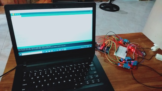
Hello everyone, welcome back to my channel. This is my 4th tutorial on how to drive a RELAY (not a relay module) with an Arduino.
There are hundreds of tutorial available on how to use a "relay module" but I could not find a good one that shows how to use a Relay and not a Relay module. So, here we are to discuss how a relay works and how we can hook it up to an Arduino.
Note: If you do any work with "mains power" such as 120v or 240v AC power wiring, you should always use proper equipments and safety gears and determine whether you have adequate skill and experience or consult a Licensed Electrician. This projects is not intended for use by children.
Blog: https://diyfactory007.blogspot.com/2018/04/driving-relay-with-arduino.html
0 notes
Text
A Year of Bittersweet Capstone
This school year has been extra challenging for us. Not just because it is our last year in high school but because of our capstone subject. Every time I hear that word, it seems very daunting and bothering at some point. Knowing that I have a few knowledge about wirings and how it works, I have already prepared myself on the amount of stress capstone may bring. As I am writing this personal blog, it amazes me on how I can look back at some of the hardest part of this school year and how I can finally say 'Salamat God kay tapos na'. My biggest achievement is finally relating to Aristotle's 'The roots of education are bitter, but the fruit is sweet.' This is truly hard yet rewarding task for all of us. I am very glad we are able to make our project as we have envisioned it to be.

Imagine if we were given the whole school year just to work on this project without other tasks, it would be the ultimate dream. Flying agricultural drones and robots equipped with artificial intelligence? If only we were given enough time for it, it would not be impossible. Of course, in reality, there are a lot more to do and accomplish in school. We had to juggle our time between doing school works for the whole day and going to a group activity for this project after school.
To be honest, I think our school is not ready for this subject and so are the students. The school is introducing robotics in the subject but there are only few teachers who are knowledgeable on programming. We cannot just solely rely on those Indian people on YouTube to teach us all of these things. Programming is new to us, especially we haven't had any computer-related subjects. We only had ICT subject when we were in 7th grade and nothing else. I also know some students in previous school years having the same subject who had the same struggle. However, since this is part of the new curriculum of K to 12, we cannot do anything but to bear with it. Also, as a student, we also wanted to do our best for the project but we lack support. It is ironic that the school is not even initiating a seminar or a workshop for programming but is having a subject for robotics. This is our struggle. I would not be shocked if other students would encounter this problem too in the next coming years. Unless the school would really take it seriously in coming up with ways on how to make students be ready and equipped for this subject and the so-called 'Industry 4.0', everything would be fine.
I salute all those programmers in YouTube who are very willing to share their innovative ideas to their subscribers. This allowed us to at least have an overview on how to properly connect and wire all the sensors. Following the instructions in YouTube was somewhat easy but programming was the hardest part since some were not willing to share their codes for the Arduino. Although they also film their codes but sometimes it is just 2 seconds of the whole instructional video. It's funny how we were so desperate to know the code that we had to screenshot some clips of the video and zoom in just to get an idea of it. We were totally clueless at the start of the year.
During our second semester, we were thankful that we had the subject Empowerment Technology. This subject was not a burden to us like how other subjects would feel like. It even made things easier for us by guiding us what to do in our projects. Calling it a blessing in disguise? I'd say yes. Our subject teacher, Sir Rae John Arango, was very willing to help us finish our project. He even set a target date for the project. I can clearly remember when he said 'Dapat before kayo magbakasyon tapos na 'yang mga projects niyo para pag Christmas wala nang problema'. Who would not want to enjoy the holidays, right? But of course, knowing that we are procrastinators, we did not meet that target date. Sir Arango still helped us program our projects despite being busy with his Continuous Improvement Project. Even if there were 11 groups for Capstone, he managed to help us all. I truly admire how he was very passionate in helping us one group at a time. To be honest, our capstone subject was only making us knowledgeable on the proper ways in conducting the research but not on how to do the actual project itself, on how to program and build the actual robot. I bet we are all very grateful that the Empowerment Technology subject are able to do this. Doing the project was somehow a lot easier for us by since our teacher was guided us on what we need to download, search for and other sensors to buy. Sir Arango is an angel sent from heaven to us struggling students or what I prefer to call 'frustrated programmers'. We owe the success of our projects to you Sir. (Sir Arango, if by any chance you are reading this, beke nemen)

We were on our track, fully confident that we are going to be able to at least start programming our project, AgriCop. When we thought everything is going in our favor, Typhoon Tisoy came. There was a blackout in our whole province. When we thought things couldn't get any worse, we were all wrong. There was no signal for us to communicate with other groupmates and to even just search in YouTube for the project. The scariest part of it is that I even had to charge our laptop using the generator while knowing the risks of the fluctuating current. I just needed to start doing the codes but then there was no internet to search for reference. We ended up doing nothing for the whole month of December. A month away from Capstone and a month before cramming and stress because of it.
Working in a group of five made it a lot easier. Although other groups have more members in their team, I mostly prefer to work in small groups. We are the only group with all girls which made it quite difficult since when need to immerse ourselves in mechanical and electronics. We are quite good in making arts and crafts, designing things, doing calligraphies and other artworks. However, this is the complete opposite of what we are used of doing. We had to let go of the paint brushes, scissors and color palettes. Instead, we learned how to properly handle screwdrivers, how to use a grinder and most especially how to solder. It was an intimidating task for all of us but we were open to learning new things. I am also grateful to my brother who taught us how to do all of these things. We did not know what tools to use but he was there to let us borrow all of the things that we needed for the project which allowed us to save a lot of money instead of buying new tools. I am so proud of what we have learned and achieved.

We were already warned by our teacher at the start of the school year that this capstone project would really be worth a lot of money. We had to save money from what my parents give as our allowance in school because sometimes it is quite embarrassing to ask extra money from my parents for this. Also, we had to buy the most basic parts first since our group did not have enough money to buy all things at once. Capstone even tested our negotiating skills since we have figured out that some of the things we have ordered were not useful for the mechatronic system of AgriCop. So, we had to sell it to other groups who needed extra relay drivers and arduino board. We were also lucky since one of our groupmates have vouchers and her shipping fee for her orders is always 50 pesos only. We also had to wait for Shopee's promo such as during 11.11 and 12.12 Christmas sale for us to get discounts. We also asked for scrap materials like aluminum tubes to reduce our expenses. Overall, we spent about 6 thousand for this robot. For me, that is already a large amount of money since it is like the salary of a normal government employee for a month of work. I am very thankful that our parents were very supportive and would understand us if sometimes we go home late just for this project. Seeing how the AgriCop works and operates is worth the amount of money that we have invested for it.

Last week has been the most tiring week in my entire existence. It was the very first time that I have experienced studying the whole day in school, going straight to our classmate's house, eating at around 8:30 or 9:00 in the evening, losing track of time, staying awake until 4 o' clock in the morning and going to school at 7:30 AM. We have gone through this cycle every day last week. It was physically and mentally draining. We also had different summative tests and projects to pass aside from the AgriCop. We did not even have the time to review or even do requirements in other subjects. Staying up late was the most challenging part of it. My father would always remind us to get enough hours of sleep but at that time we just cannot. We were deprived of sleep. The schedule of final defense was moved a week earlier than the planned date. Every single day we were required to pass different outputs in capstone. At that time there was no room for 8 hours of sleep but more space for eye bags and eye strain. We already divided the tasks for each of us. I was assigned to work on the write-up. There was this one time that I can't really handle my sleepiness anymore that I took a nap for an hour not minding how many mosquitoes were already buzzing in my ears and biting my arm. Four o' clock in the morning is our usual 'dismissal' in the group activity. We are so blessed that the father of one of our groupmates would drive each us to our houses even if it is already early in the morning. My father also does the same thing when we decided to do group activity for the last few days in our house. We are very grateful and blessed.

We have invested so much in this project, our effort, money, sleep and sacrificing time for other subjects. At some point, we felt like we were the underdog out of all the groups but I am glad that each of us did not let go of that little hope that we can pull this through. We were all tired. I saw it in the eyes of my classmates and even in my own groupmates' as we go to school in the morning after probably not getting enough rest at all. I heard their voices saying 'Di ko na aram ang uunahon', 'Papano na ini', 'Di pa ngani ako nangarigo nan nagmahaw'. We were all going through the toughest part of our life as graduating students. I always believe that the only way to overcome a situation is not to run away from it but to get through it with high hope. I am very thankful that I have groupmates who would always lift each other up and still laugh at the dumbest things that we would do at 2 AM. The perfect term to describe all of us is 'sabaw'.

We were nervous and at the same time excited during the poster presentation of our project. This was the time that we did not have any practice of our script. We just had the time to read the lines once and then the first judge already stood in front of us. We were glad that they get to appreciate our projects and made suggestions for the design of AgriCop. There was this one science teacher which was part of the judges who made me teary-eyed. Not because I was scared or intimated but because she understands what we have gone through and she was really listening and paying attention to every detail that we are saying. She told us that she really appreciates the Mechatronic System of AgriCop that is not complicated compared to other groups. She also mentioned about how it could help farmers to easily replicate our study using mechatronics. She appreciates how we put into consideration the situation of the farmers and the knowledge that they have when it comes to programming. In every word that she mentioned, I could sincerely feel her genuine appreciation to our project and how we, girls, are able to come up with AgriCop. Finally, there was at least this one teacher who can relate to all of our struggles and how hard research is. She understands our situation and acknowledges all the efforts that we have put in this project. We needed that extra boost of support at those moments. I would forever cherish all the kind words that she said to us.

The day of the final defense came. At this same day, we were also preparing for the awards in school so it made it extra hassle for us. We were practicing the script at around 10 AM and also writing down all the possible questions of the panel. I remember how nervous we were entering the STEM B room to present our project. We weren't able to finish our presentation since we exceeded the time limit and the panel already told us to show the remaining slides. The teachers were very kind to us which is the complete opposite of what we were expecting. I guess they already knew the amount of effort, money and sleepless nights we have invested for this. They commended and congratulated us for the project. They also mentioned that they witnessed how our research studies have evolved from simple studies in junior high to a research product with quality. We feel blessed that the AgriCop functioned properly and cooperated well with us. Leaving that room made us all sigh in relief. Finally, our capstone project is done. After a whole school year of working on it, it is already finished. I remember how we were all jumping around outside the room saying 'Tapos na!'. We also had a mini celebration and ate sotanghon and puto which was the food left for the panels. I can still feel that relief we all felt at that moment. A truly rewarding moment.

Capstone has been a very tough subject for all of us. We weren't prepared for it, especially in programming but we are thankful that our Empowerment Technology teacher guided us all the way. Being in a group of all girls did not became our weakness, instead Capstone allowed us to work even harder and build stronger friendship. I will leave all of the stress, rants, negative emotions, will and hopes that I have had doing this project here in my blog. As I venture more on robotics in college or in my future job, I'll look back at this and remember how we all started. I'd remind myself of a struggling student without any idea of robotics but manages to overcome it and finish strong.
1 note
·
View note
Text
A Semi-Automatic Turntable: Part 1
Part 1: Intro & Subsystems
For a while now, I've been considering using an Arduino in order to automate the operation of the turntable on my layout. After considering several 'bolt-on' additions, I realised that trying to add indexing to the existing, DC-motor mechanism would be cumbersome. As such, I decided to replace the drive mechanism with a stepper motor, and use that for indexing.
My original plan was to just add indexing, with a keypad to select the desired track. But then I realised that I could take it a step further, and make it fully automated. This didn't quite work out, and I instead ended up with a semi-automatic version. This is how it ended up working:
youtube
I decided on this approach for two reasons: 1) I couldn't find sensors which would give me the accuracy required while being hidden. That is, there was always a trade-off between accuracy and visual impact. 2) My layout is a backwoods operation, with operating ground throws to change the turnouts.
As such, I wanted to have a hands-on element to the turntable's operation. While testing the fully automatic version, I found that I felt a bit 'disconnected' from what was happening. So in this series of posts, I'll be covering how I built this final version, and some of the things I learned along the way.
This first part will cover the construction and testing of the subsystems that make up the turntable controller. Some of these were built or adjusted after I'd decided to go from a fully automatic to a semi-automatic system.

I started by working out how to operate the stepper motor, a 12-volt NEMA-17 motor. This was the key to the whole system, and I'd never used one before. In order to drive it, the Arduino controls an A4988 chip. This is the red board in the photo above, with a silver heatsink on it. It takes a control signal from the Arduino, and a completely separate power supply for the motor itself. The only additional component required is the capacitor, to protect the inputs for the motor power supply, as well as a 10K ohm resistor to hold down the motor step pin when not in use.
The A4988 offers the option to drive the motor in 'microsteps', in which each pulse moves the motor by a fraction of a full, 1.8-degree step. Pins MS1, MS2 and MS3 on the A4988 are used to set which fraction is used. Setting them high, in various combinations, allows the A4988 to drive the motor in increments as little as 1/16 of a step. At this point in the build, I wasn't sure what resolution I would need. As such, I added a 4-way DIP switch between these three pins and the +5v rail, to allow me to try them. One of the switches from the DIP switch wasn't used.
Working from what I'd worked out on the breadboard, I built a motor driver board to be used in the final build.

My next step was to test that the motor had enough torque to move my locomotives. My heaviest locomotive is my boxcab, which was built on an Athearn blue-box mechanism. As such, it weighs in at around 450g.

I cut a length of wood to the same length as the turntable bridge. After finding the centre, I attached the driveshaft adapter I'd had 3D-printed by Shapeways. This fits around the shaft of the stepper motor, with a flat section where the drive shaft is flattened. It took a few tries at different sizes before it fit perfectly.

To simulate the load, I used a box of old motors I'd bought at a sale at my model train club. They were the only thing I had to hand which were heavy enough. I taped them to the top of the board, until it weighed 500g (for a bit of wriggle room). I then placed it on the end of the driveshaft.
youtube
The motor was able to move the load without any problems. With that confirmed, I started working on the components for the control panel.
The original, fully-automatic design had two 3mm LEDs on it, one red and one green. These were to have been 'stop' and 'go' signals for when the automated turntable was operating. The other component for the control panel was a 4-digit LED display to show the address of the currently selected locomotive. Owing to the change in focus for this project, the design of the control panel changed slighlty between the initial and final versions. But before I could build it, I needed to build the 4-digit LED display.

I'd done one of these on the base station for my DCC system. On that occassion, I'd made the display from four individual 7-segment displays, driven my a MAX7219 LED driver chip. This time around, I decided to use a 4-digit display, driven by the same chip. With the four digits in the one package, it only needs 12 connections for full functionality. I wired the 4-digit display to the MAX7219, leaving out the connections for the decimal points between the digits. They weren't needed.
To test it, I wrote an Arduino sketch (program) that counted up to 10,000 in 0.01 second increments and ran it. I was able to re-use a function I'd written for the base station, which will take a number up to 9,999 and display it across the four digits of such a display.
With that done, I was able to build the control panel itself.

When I decided to go from automatic to semi-automatic operation, I replaced the red LED on the panel with a single-pole, double-throw momentary contact switch. This is used to turn the turntable, via the stepper motor. I'd used a length of Cat5 network cable to connect the control panel to the Arduino, to keep things organised. This had a spare wire left in it. As such, I was able to wire the switch to the ground connection, then use the original wire for the red LED and the spare wire to connect to each side of it.

In order to get the program to work properly, there are a couple of points at which it pauses to prevent a false triggering while the locomotives move on and off the turntable. After initial testing, I realised it would make things clearer if there were an indication of when these pauses were occurring. So I added a yellow LED to the control panel, to indicate when the system was active. If this LED is on, then the turntable can be turned, locos can arrive and depart, etc. If it's off, then the system is paused.
Once completed, this control panel was installed in place of the original control panel on the fascia. The original panel had just had two switches, a DPDT rocker to control the DC turntable motor, and a 12-position rotary switch to select track power.

Next up was the occupancy detector, to determine when a train was on the bridge. The design of this turntable provides constant power to the tracks, with an auto-reverser reversing the polarity as needed. After a bit of experimentation, I found that wrapping the wire at least four times through the coil was enough to allow it to detect the current of a sound decoder at idle. At least, that's what I thought.
It's the first time I've used a coil like this, and it was sold amongst other Arduino modules. As such, I thought I would be able to plug it straight into an analog pin of the Arduino, and take a reading from that. This was not actually the case. As DCC is very close to AC current, I ended up getting several values from the coil over the course of a second, including 0, which would create false negatives. After asking about this on the Arduino forums, I learned that the way these coils work is by generating AC current, in response to the current going through them. I thought they just sensed it. As such, I'd accidentally been putting 38v of AC into the analog pin I was using, and had damaged it.

In order to use the coil for DCC occupancy detection, some supporting circuitry is needed. I found this article here, outlining how to build a sensor out of such a coil. I didn't have the exact same transistor, and instead used a BC548 NPN general-purpose transistor. The yellow wires off the board go to the two sides of the coil, and the green one goes to the Arduino.
Once I'd built this, I tested it with my locomotives before connecting it to the Arduino. This was where I discovered something interesting. The circuit is designed to give a digital output, in which anything less than 1.5v on the Arduino pin is counted as a 0, and anything above it as a 1. When testing it, I found that it produced an output of 3.7 volts when no locomotive was present, and that this dropped when one was detected. However, about half of my locomotives only dropped it to a value above the 1.5v required for a digital 0, yet less than the 3.7v of the 'nothing detected' state. As such, I connected it to another analog pin on my Arduino. These voltages translated to an analog read value above 900 when nothing was detected, and below 900 when something was. Thus, I used an analog reading with a threshold of 900 in the program function to detect occupancy.
At this point, the next item to be tested was a socket for an XBee wireless module. I'd already used these to make my DCC system, as well as to transmit the address of the incoming locomotive to my automated staging controller. As such, I pulled out a spare XBee, and configured it identically to the one for the staging controller. It'll be used for the exact same purpose, receiving addresses when a locomotive is dispatched. I tested it by connecting it to the Arduino, then rigging up the Arduino to display the received locomotive address on the LED display.

The next step was to prepare the Arduino shield. I usually use prototyping shields for the connections to the Arduino, as this means that I can just unplug the shield and pull the Arduino out if any software updates are needed. I've found it's easier to solder two wires together under the layout, than it is to solder to a shield. So I added small lengths of decoder wire to each output.
My turntable has 11 tracks around it, and I didn't have 11 spare pins on the Arduino. Instead, I used a 16-channel multiplexer with channels 1-11 wired to a bank of relay switches. I started counting at channel 1 instead of 0 in order to make the software code a bit simpler. The resistor on pin 4 is 220 ohms, and is connected to the green LED on the control panel. At this point, I hadn't added the yellow LED to the control panel. When I did, I added a 220 ohm resistor to pin 13, and connected this LED in there.
The other component of note is the variable resistor connected to pin A1. I was originally going to have a light detecting resistor in the turntable lead track, to trigger the Arduino when a train was leaving or arriving. However, after getting the occupancy sensor working reliably, the LDR was no longer needed.

The final building block was the relay bank. I'd bought a 16-relay module off eBay, and I installed it behind the fascia, next to the control panel. The wires from the original 12-way rotary switch to the tracks came out here, so by putting it in this position, I didn't have to do too much in the way of rewiring. Each track was wired to the normally-open contacts on the first 11 switches, with wires from the common side of the relay going to the track bus. The multicoloured ribbon cable on the far side of the relay bank goes to the Arduino, with two wires for the power supply and the other wires for the track control.
With all the building blocks worked out, the next step was to install the stepper motor and modify the turntable. This will be covered in part 2 of this writeup.
4 notes
·
View notes
Text
Multifunctional bicycle light
Do you want dynamic LED turn signals for your bicycle? Do you also want a dynamic brake light? Or maybe you want an emergency signal?
And all that WITHOUT a microcontroller? (only logic circuits)
youtube
Part one. Basic functionality
If you drive a car, it's very likely that you've come across an uncomfortable situation involving a cyclist at least once or twice in your life. Bikes can be quite unpredictable on the road and you often have to guess what maneuver they'll pull next. Electrically-powered bicycles and scooters are especially erratic when it comes to sharing the road. And once it gets dark out, the situation worsens twofold.
Recently, I started dabbling in electric biking myself. However, I would say that factory reflectors on it aren't the best way to make your electric steed easily noticeable on a bike path. Therefore, it's time to unholster my trusty soldering iron and make this world brighter put together some LED turn signals.
I really like the dynamic LED turn signals that come pre-installed on some modern cars. I wish I had something like that on my bike. The most obvious solution would be to use an Arduino and LEDs with a WS2812 chip. Nowadays you can find a microcontroller with its own firmware in something as mundane as a teapot and no one would be surprised by it. However, the fact that this can be realized by just using some "hard" logic and without a microcontroller can really leave some modern electronics engineers scratching their collective heads. Unsurprisingly, that's exactly what I found myself doing when I came across the "RF74xxID The Multifunction Passive 7400 RFID Tag" project on the interwebs.
At the time I was so absorbed by microcontrollers that I didn't even think about the fact that just a couple of decades ago, electronics engineers somehow managed to get by without them, and even launched rockets into space.
Anyway, at some point this became an obsession for me, and I decided to design a dynamic turn indicator circuit using only 7400-series integrated circuit. And with that, I welcome you to dive a little bit into retro electronics with me.
The proposed dynamic turn indicator control circuit doesn't involve any expensive or scarce components. It's easy to reproduce and it works immediately after assembly (if everything is soldered properly).
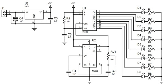
The high output of the first shift register is connected to the data input of the second register. You can also connect the data input of the third register from the high output of the second register. Then you can just keep going with this chain pretty much endlessly.
When adding another circuit, you should immediately add a trim resistor with a lower resistance. I recommend using 20kΩ.
Now let's talk a little bit about powering the circuit. The 7805 voltage regulator allows you to get +5V to power the circuit. The input voltage can vary from +7.5V to 15V. But don't forget that the 7805 can heat up quite a bit, in which case you should use it with a heat sink. The 7805, like any other radio component, also has an operating current limit. Take this into account when selecting the operating current for the LEDs. The total simultaneous current consumption of all the LEDs must not exceed the maximum operating current of the voltage regulator. It would be even better to have a safety margin of about 20 percent.
Do not use this circuit to modify a car! Personally, I'm against modifying cars from their factory state. But you can very well implement this circuit on something like a children's electric car, for example.
If you really want to use this circuit to modify a bicycle or kid's electric car, a turn signal relay is not an absolutely essential component. The circuit can flash on its own as long as there's a supply voltage. For this, all you need to do is connect a transistor instead of the D8 LED. The Q1 transistor will reset the outputs of the shift register after all the lights are activated. For this setup, I recommend using an RV1 variable resistor with a resistance of 100kΩ.
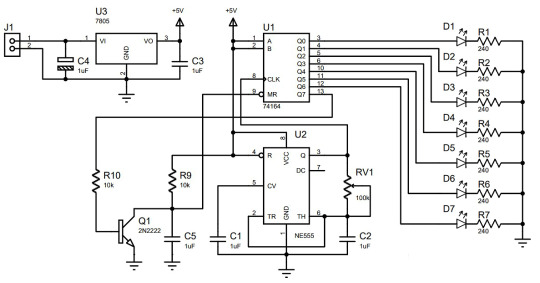
If you cross the first two circuits and replace the yellow LEDs with red ones, you get a dynamic brake light. You could simply connect the second strip of LEDs in parallel to the first one, but it is better to use a second circuit board. Firstly, it won't overload the current outputs of the shift registers, and secondly, it will be much easier to trace the board in the form of a narrow strip.

Part two. Cool device :) Even at the design phase of the previous dynamic turn indicator circuit, I realized that its functionality wasn't enough for me. I decided to pack both the right and left turn signal functions into a single strip of LEDs. The dynamic way in which LEDs light up is very good at indicating my intended turn direction. I also decided to add some functionality to the circuit to allow for a "sidelight/parking light" mode.
I don't usually ride very fast, so I thought that having brake lights seemed excessive. Besides, it would mean that I have to add additional sensors and wires to the system.
The "challenge" is also supplemented by some rather strict conditions. The device must be built around eight 5050 RGB LEDs which will dynamically light up to indicate right and left turns, and it has to include a parking light/sidelights mode. An important condition was that the circuit had to be made on a single-sided printed circuit board with the LEDs placed in the center of the board.
In the end, I formulated the following requirements for the circuit's functionality:
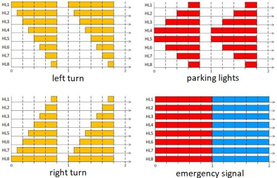
When power is supplied, the parking light/sidelight mode is immediately activated. The indication is performed by switching on the red LEDs. The switching intervals of the LEDs have equal values and the total repetition rate is about 1Hz.
The turn signals are activated by closing the "Button_Left" and "Button_Right" contacts with the common wire, i.e. closing the common wire with the "Button_Left" contact for a left turn indication and with the "Button_Right" contact to indicate a right turn. The indication is performed by simultaneously switching on the red and green LEDs. The switching intervals of the LEDs also have equal values, with a total repetition rate of about 1Hz. Simultaneously closing the "Button_Left" and "Button_Right" contacts with the common wire is an unacceptable combination and is mechanically prohibited by the design of the bike's handlebar buttons.
To prevent the blue diodes of the RGB LEDs from being neglected, I decided to add an emergency signal to the circuit. But that idea came to me a little later. I only implemented it in the second version of the board. The emergency signal mode is activated when the "Button_Strobe" contact is closed with the common wire of the circuit. The indication should be performed by alternately switching on the red and blue LEDs. The switching intervals should also be approximately 1Hz.
The previous turn signal circuit was realized using a shift register. It only had the function of indicating a turn in a single direction. But now I need to have the same dynamic lighting effect, but to show turns in either direction using the same strip of LEDs. However, doing this with shift registers and a diode matrix seemed like overkill even to me. But there had to be some kind of special feature in the circuit.
The basis of the circuit is a block of comparators, which control a line of 8 LEDs. The comparator compares the linear rising voltage from the LRVG (Linear-Ramp Voltage Generator) with the reference voltage from the RVS (Reference Voltage Source) also known simply as a voltage reference. The RVS generates 8 trigger thresholds to control each individual LED. The LED control scenario depends on how the control logic switches the RVS.
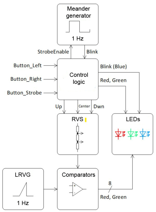
The RVS is a voltage divider made with resistors. There are voltage leads between the resistors that connect to the inverting inputs of the comparators. The voltage divider also has three special lines: "Up", "Center", and "Dwn". The reference voltages at the comparator inputs can change depending on how these lines are connected to the power circuits.
The control logic can switch the RVS in the following ways:
The "Center" line is disconnected from the power supply circuits, the "Up" line is connected to the positive power supply, and the "Dwn" line is connected to the common wire. With this switching scenario, the voltage at the outputs of the voltage divider increases from the lower "Dwn" lead to the upper "Up" lead. This corresponds to switching the LEDs to the left turn mode.
The "Center" line is disconnected from the power supply circuits, the "Up" line is connected to the common wire, and the "Dwn" line is connected to the positive power supply. In this case the voltage at the outputs of the divider will be distributed in the opposite manner: maximum voltage on the lower "Dwn" lead, minimum voltage on the upper "Up" lead, and the voltage will decrease from the lower to the upper lead. This corresponds to switching the LEDs to the right turn mode.
To control the LEDs so that they are in the parking light mode, the "Center" line connects the center of the voltage divider to the positive power supply, and the "Up" and "Down" lines are connected simultaneously to the common wire. This divides the voltage divider into two halves, and the reference voltage will decrease from the center to the upper and lower leads of the divider.
In the emergency signal mode, the "Center" line is also disconnected. Meanwhile, the "Up" and "Down" lines are simultaneously connected to the positive power supply or to the common wire. If a connection is made to the positive power supply, the positive power appears on all the leads of the voltage divider at once, and the outputs of all the comparators will be open at the same time. If "Up" and "Dwn" lines are connected to the common wire, the outputs of all the comparators will be simultaneously closed.
The first version of the circuit turned out to be even simpler than I could have imagined. I double- and triple-checked the circuit several times in the simulator and analyzed it empirically. According to my estimation, everything should work. However, this circuit didn't make it to the prototyping stage.
Click to zoom
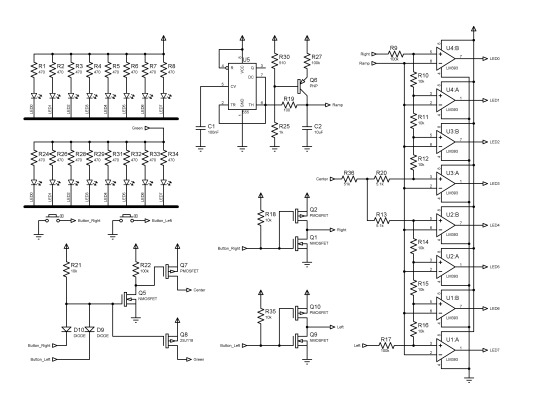
To facilitate installation to the bike, the right and left turn buttons are closed to ground. There is an OR circuit on the D9D10 diodes and the R21 resistor. The Q5 transistor inverts the button signal to control the Q7 transistor. The Q7 transistor closes when either button is closed and disconnects the "Center" lead from the positive power supply. At the same time, one of the half-bridges (Q1Q2 or Q9Q10) diverts its side of the voltage divider to the positive power supply. The other side remains diverted to ground.
The NE555 timer generates the sawtooth pulses. The Q6 transistor provides a linear charge to the C2 capacitor. The C2 capacitor is charged to 2/3 of the supply voltage. Then the timer switches and the capacitor is discharged through the R19 resistor. The resistor limits the discharge current of the capacitor. This also allows the timer to trip when C2 discharges to 1/3 of the supply voltage. Thus, the sawtooth pulse has a range of 1/3 to 2/3 of the supply and has a rising shape.
The R9, R17, and R36 resistors have a higher resistance than the other elements of the voltage divider reference. This is necessary so that the divider's voltages are in the same range as the sawtooth pulses.
The complete circuit differs from the previous one in that it has slightly more complex logic for controlling the LEDs. I decided not to mess around and make it on CD4000 series logic chips. Compared to the 74NS00 series, the CD4000 has an extended supply voltage range. Thus, the circuit works from 2.7V to 9V.
Another NE555 oscillator has been added to the circuit for the emergency signal mode. Its pulses determine the timing of the red and blue flashes. The rest of the circuit works in the same way as the previous one.

Click to zoom
I once again double-checked everything. The circuit turned to be incredibly simple, which is probably why I continued to doubt up to the very last moment that it would work when put to the hardware. With the help of an iron, I quickly assembled the prototype and everything worked as it was supposed to on the first try.


The board looked excellent when it was printed in green! All it took was six simple microchips and a handful of passive components, and there you go – another puzzle is solved.

The results of the work can be found in the video.
youtube
0 notes
Text

The Arduino 4 Relays Shield is a solution for driving high power loads that Arduino's digital IOs cannot control due to the current and voltage limits of the controller. The Shield features four relays, and each relay provides two pole changeover contacts (NO and NC). The two changeover contacts have been put in parallel to increase the current output limit. In addition, four LEDs indicate each relay's on/off state.
Arduino Four Relays Shield - Copperhill (copperhilltech.com)
0 notes
Text
Quality Arduino Alternative for Industrial Use
For the best quality Industrial Application of Arduino hurry up to visit Norvi. This is a leading platform offering a wide range of products available at affordable prices. Invest in Industrial Application of Arduino and you will certainly get the best value for your money. Other than real-time acquisition and pushing to an IoT platform, data loggers are one method of keeping track of values and analyzing. The industrial world is full of various types of data loggers. These include the following types:
USB loggers which are used for Short-term trend logging with manual offload
Bluetooth (BLE) Loggers with Wireless data access via mobile devices
Web-based Systems with Long-range wireless internet access
Wireless Sensors with Short-range centralized data collection
With the ESP32 based NORVI IIOT, you can build any of those solutions in the simplest way possible. You can invest in Arduino Wifi Data Logger and see that costs can also be kept lower compared to other data-loggers. NORVI IIOT ESP32 Data-logger with Web-access is the best choice offering almost all the acquisition types you need to build the Real-time data logger with web access. It includes digital inputs (As counters or ON-OFF status detection), 0-10V Voltage Analog Inputs, 4-20 mA Current Analog Inputs, temperature inputs, load cell inputs, RS-485 communication interface, and 12C communication interface. As NORVI IIOT supports all the above input types which means you have access to the real-word parameters. The next step is storing them with time stamp. Believe it or not, NORVI IIOT AE04 range is an amazing data-logger with Web access. To keep track of time and micro-SD card support providing storage facility for the data, you can also take advantage of DS3231 Real Time Clock (RTC). You can also store the needed data in microSD card in CSV format or in a database with SQLite3 library.
Due to ESP32 based NORVI IIOT, it is also possible to implement wireless access for the logged data and real-time data. You can access or view the data by using WiFi if you combine few libraries of ESP32 Arduino. There are several examples for ESP32 to work as a datalogger and Web-interface for real-time data.
If you want Arduino Alternative for Industrial Use you can rely on Norvi again and again. Remember that if you have access to efficient hardware, you will be able to finish your project in the fastest possible time. GPIO pins are isolated and connected to the relays and inputs. You can control relays and inputs via GPIO. You will be provided with LED Indicators for Inputs, Outputs and Seria, Arduino libraries for reading analog inputs and driving OLED Display, Expansion port with UART, SPI, I2C, and 2 GPIO which lets you access external devices or modules. You can also enjoy USB Connection as a usual Arduino board to connect with the Arduino IDE. What’s more, MicroSD card support is also provided. This means that you can add a micro SD card for expanding its capacity, for applications like dataloggers. Just order this Arduino Alternative for Industrial Use and be sure to enjoy these benefits.
0 notes
Text

L298N Motor Driver Module 2A
This L298N Motor Driver Module is a high power motor driver perfect for driving DC Motors and Stepper Motors. It uses the popular L298N motor driver IC and has the onboard 5V regulator which it can supply to an external circuit. It can control up to 4 DC motors, or 2 DC motors with directional and speed control This motor driver is perfect for robotics and mechatronics projects and perfect for controlling motors from microcontrollers, switches, relays, etc. Perfect for driving DC and Stepper motors for micro mouse, line-following robots, robot arms, etc.
Note: It is recommended to buy a good quality version of this product. You can buy it by clicking here: L298N Motor Driver Module – Good Quality. The reason is that the good quality version product has a better quality of components as compared to standard ones.
Pins:
Out1:Motor A lead out
Out2:Motor A lead out
Out3:Motor B lead out
Out4:Mo (Can actually be from 5v-35v, just marked as 12v)
GND :Ground
5v :5v input (unnecessary if your power source is 7v-35v, if the power source is 7v-35v then it can act as a 5v out)
EnA :Enables PWM signal for Motor A (Please see the “Arduino Sketch Considerations†section)
In1 :Enable Motor A
In2 :Enable Motor A
In3 :Enable Motor B
In4 :Enable Motor B
EnB :Enables PWM signal for Motor B (Please see the “Arduino Sketch Considerations†section)
Usage: H-bridges are typically used in controlling motors speed and direction but can be used for other projects such as driving the brightness of certain lighting projects such as high powered LED arrays.
Two things to mention: Make sure you have all of your grounds tied together; Arduino, Power source, and the Motor Controller. The PWM Pins are unnecessary if you do not want to control PWM features.
Arduino Sketch Considerations: The Arduino code sketch is pretty straightforward. Since there isn’t a library for the L298N Dual H-Bridge Motor Controller you just have to declare which pins the controller is hooked to. The “int dir(number)Pin(letter) pins can be connected to any available digital pin you have available, as long as you declare the correct pin in your sketch. This makes the L298N Dual H-Bridge Motor Controller very versatile if your project is using a lot of Arduino pins. The int“speeding(letter)†pins need to be connected to a PWM pin on the Arduino if you want to enable speed control through PWM. As a quick cheat I have included a list of PWM pins for the main two types of Arduino I use: AT MEGA PWM: 2 to 13 and 44 to 46. Provide 8-bit PWM output with the analogWrite() function. UNO PWM: 3, 5, 6, 9, 10, and 11. Provide 8-bit PWM output with the analogWrite() function. Note: Built-in 5v power supply, when the driving voltage is 7v-35v
Features: -Current Sense for each motor. -Heatsink for better performance. -Power-On LED indicator. -Drives up to 4 motors.
0 notes
Text
Solid State Relays ekuivalen semikonduktor dari Relays elektromekanis
Tidak seperti Relays elektro-mekanis (EMR) yang gunakan kumparan, medan magnet, pegas dan contact mekanis buat menjalankan dan memindah persediaan, Relays situasi padat, atau SSR, tidak punyai sisi yang bergerak tapi gunakan karakter listrik dan optik dari semikonduktor situasi padat buat mengerjakan input ke output isolasi dan peran switching. Seperti sama Relays elektro-mekanis normal, SSR siapkan isolasi listrik komplet di antara contact input dan outputnya dengan outputnya melakukan tindakan seperti sakelar listrik konservatif lantaran punyai resistansi yang tinggi sekali, nyaris tidak berbatas waktu nonkonduktor (terbuka), dan resistansi yang paling rendah waktu mengerjakan (tertutup). Solid State Relays bisa didesain buat memindah arus AC atau DC dengan gunakan SCR, TRIAC, atau switching transistor output bukannya contact mekanis yang rata-rata terbuka (NO).
Sementara Relays Solid state dan Relays elektro-mekanis secara prinsip sama lantaran input tegangan rendahnya diisolasi secara elektrik dari output yang memindah dan mengendalikan beban, Relays elektro-mekanis punyai transisi hidup contact yang terbatas, bisa menggunakan banyak area. dan punyai kecepatan sakelar yang lebih pelan, terlebih Relays dan kontaktor daya besar. Relay Solid state tidak punyai batas sesuai itu. Karena itu, keuntungan penting Relays Solid state ketimbang Relays elektro-mekanis konservatif merupakan kalau mereka tidak punyai sisi yang bergerak buat aus, dan oleh lantaran itu tidak ada soal refleksi contact, bisa aktifkan "ON" dan "OFF" semakin lebih cepat dibanding Relays mekanis. armature bisa bergerak, dan turn-on tegangan 0 dan turn-off arus 0 melenyapkan kegaduhan listrik dan transien.

Relays Solid state bisa diperoleh dalam paket standard yang siap mulai dengan cuma sejumlah volt atau ampere sampai beberapa ratus volt dan ampere kebolehan switching output. Tapi, Relays Solid state dengan posisi arus yang tinggi sekali (150A plus) masih begitu mahal buat dibeli lantaran semikonduktor daya dan kriteria heat sink, dan karena itu, kontaktor elektro-mekanis yang tambah murah masih dipakai. Serupa dengan Relays elektro-mekanis, tegangan input kecil, rata-rata 3 sampai 32 volt DC, bisa dipakai buat mengendalikan tegangan atau arus keluaran yang semakin lebih besar. Umpamanya 240V, 10Amp. Ini membuat baik buat antar-muka mikrokontroler, PIC, dan Arduino jadi isyarat arus rendah, 5 volt dari ungkapkanlah mikrokontroler atau gerbang pemikiran bisa dipakai buat mengendalikan beban serangkaian tersendiri, dan ini dijangkau dengan pemakaian opto- isolator.
Input Relays Situasi Padat

Satu diantaranya bagian penting dari Solid State Relays (SSR) merupakan opto-isolator (pula dimaksud optocoupler) yang berisi satu (atau mungkin lebih) dioda pemancar sinar infra merah, atau sumber sinar LED, dan feature peka poto didalamnya. satu kejadian. Opto-isolator mengurung input dari output. Sumber sinar LED tersambung ke sisi drive input SSR dan siapkan lanjutan optik lewat sela ke transistor peka poto, pasangan darlington, atau triac yang bersisihan. Di saat arus melalui LED, itu menyalak dan sinarnya diutamakan melalui sela ke foto-transistor/foto-triac. Karena itu, output dari SSR opto-coupled dihidupkan "ON" dengan memberinya energi di LED ini, rata-rata dengan isyarat tegangan rendah. Lantaran hanya satu pertalian di antara input dan output merupakan secuil sinar, isolasi tegangan tinggi (rata-rata sejumlah ribu volt) dijangkau lewat isolasi opto intern ini.
Opto-isolator bukan sekedar siapkan tingkat isolasi input/output yang bertambah tinggi, akan tetapi bisa juga mengantarkan isyarat dc dan frekwensi rendah. Pula, feature LED dan fotosensitif bisa serius terpisah keduanya dan dicampurkan secara optik lewat serat optik. Circuit input SSR bisa terbagi dalam resistor penghalang arus tunggal yang dirangkai seri dengan LED opto-isolator, atau circuit yang lebih kompleks dengan penyearah, penyusunan arus, pelindungan polaritas kebalik, pemfilteran, dan sebagainya. Buat aktifkan atau hidupkan "ON" Relays situasi yang dipasarkan jadi konduksi, tegangan yang makin besar dari nilai minimalnya (rata-rata 3 volt DC) mesti diimplementasikan ke terminal inputnya (sama dengan koil Relays elektro-mekanis). Isyarat DC ini bisa di turunkan dari sakelar mekanis, gerbang pemikiran, atau pengatur micro, sama yang ditampakkan.
0 notes
Photo

* 🇧🇷 #tbt - Board Mini Arduino Mega 2560 com Display Nokia 5110 ou Display TFT 1.8. shift register HC595 para acionamento de reles . Esse projeto foi utilizado para controle de Mini Painel Solar Fotovoltaico ---‐---------------------- youtube.com/ProjetosEletronicos ---‐---------------------- 🇺🇸 #tbt - Board Mini Arduino Mega 2560 with Nokia 5110 Display or TFT 1.8 Display. shift register HC595 for relay drive. This project was used to control Mini Photovoltaic Solar Panel -------------------------- #arduino #arduinouno #arduinonano #arduinomega #painel #fotovoltaico #display #nokia #maker #diy #geek #eletronica #eletrônica #hardware #walproj #projetosmaker #projetoseletronicos (em Projetos Eletronicos) https://www.instagram.com/p/CCKXBvKjro_/?igshid=1hh9040acil4e
#tbt#arduino#arduinouno#arduinonano#arduinomega#painel#fotovoltaico#display#nokia#maker#diy#geek#eletronica#eletrônica#hardware#walproj#projetosmaker#projetoseletronicos
1 note
·
View note
Text
72v 700w Brushless Motor Controller Driver Board

Brushless Motor Speed Controller
Items in search results
DC 36V 48V 72V 60V 700W Brushless Motor Drive Board Balanced Car BLDC Controller
EUR 13.49
+ EUR 1.13 postage
From Hong Kong
DC72V 4000W Electric Bicycle Brushless Motor Speed Controller for E-bike Scooter
EUR 236.18
Free Postage
From China
DC 36V-72V 700W Brushless Motor Controller Hall Motor Balanced Car Driver Board
EUR 13.49
+ EUR 1.13 postage
From Hong Kong
12V 24V 36V 48v 72V 30A DC MOTOR SPEED governor CONTROL PWM HHO RC CONTROLLER
EUR 9.33
+ EUR 1.13 postage
From Hong Kong
700W BLDC driver board DC brushless no Hall sensor motor control dc 36-72v 60v
EUR 14.94
+ EUR 1.13 postage
From Hong Kong
140A 200V 48V 72V current limited DC motor speed controller PWM RS232 arduino
EUR 97.58
+ EUR 10.65 postage
From Hungary
72V 1200W Electric Bicycle E-bike Scooter Brushless DC Motor Speed Controller SP
EUR 45.00
Free Postage
From Hong Kong
200A 100V 48V 72V current limited DC motor speed controller PWM RS232 arduino
EUR 88.71
+ EUR 10.65 postage
From Hungary
70A 100V 48 72v DC motor PWM Speed Controller Reversible H bridge RS232 Arduino
EUR 79.84
+ EUR 10.65 postage
From Hungary
NEW Malin Crown CR20334-000 72 Volt DC Truck Lift Turret Drive Motor 72V
EUR 584.67
+ EUR 675.44 postage
From United States
6-72V 450W DC Brushless Motor Controller BLDC PWM Hall Driver Board 12v 24v 48V
EUR 11.13
+ EUR 1.13 postage
From Hong Kong
DC 5-72V 15A Digital Display PWM DC Motor Speed Controller Module Button Versio
EUR 5.84
+ EUR 1.13 postage
From Hong Kong
Waterproof Digital Meter DC 3.5~150V Led Voltmeter 12V 24V 36v 48v 72v car Motor
EUR 4.49 toEUR 4.94
+ EUR 1.13 postage
From Hong Kong
48-72V 1000W Electric bike Scooter Hub Motor BLDC Brushless DC Speed Controller
EUR 52.83
(EUR 52.83/Unit)
Free Postage
From Hong Kong
Malin Crown CR20334-000 DC 72 Volt Truck Lift Turret Drive Motor 72V
EUR 275.77
+ EUR 531.08 postage
From United States
1000W 60/64/72V Brushless Motor Controller For E-bike & Scooter Electric Bicycle
EUR 30.37
Free Postage
From United Kingdom
60/64/72V 1000W Electric Bicycle E-bike Scooter Brushless Motor Speed Controller
EUR 29.92
Free Postage
From United Kingdom
DC Motor 12V 120rpm
EUR 1.13
1 bid
+ EUR 3.26 postage
From United Kingdom
KP-DHV821 Motor DC servo 6÷7.4VDC standard digital 72g 40x20x39mm K-POWER
EUR 100.21
+ EUR 1.11 postage
From United Kingdom
60W 12V 24V DC Reversible Speed Reducing Brush Gear Motor (+ Bracket)
EUR 138.08
Free Postage
From China
RS Pro, 3 V, 1.5 â?? 3 V dc, 1000 gcm, Brushed DC Geared Motor, Output Speed 72
EUR 32.03
Free Postage
From United Kingdom
18V DC Motor JD 550
EUR 5.61
0 bids
+ EUR 3.25 postage
From United Kingdom
Motor Large Torque Gear Motor 775/795/895 Motor Bracket DC 12V-24V 3000-12000RPM
EUR 5.55
Free Postage
Free returns
From Hong Kong
Faulhaber Brushed DC Motor, 1.72 W, 6 V dc, 2.9 mNm, 3860 rpm, 1.5mm Shaft Diame
EUR 162.27
Free Postage
From United Kingdom
Sanyo Denki Step-Syn Motor Model 103-7500-5110. 1.82V DC, 1.3A, 0.72° step >
EUR 50.69
+ EUR 53.01 postage
From United States
DC 6V 12V 18V 24V RS-775/795/895 Motor High Speed Large Torque Dual Ball Bearing
EUR 20.88
Free Postage
Free returns
From China
60/64/72V 1000W Electric Bicycle E-bike Scooter Brushless Motor Speed Controller
EUR 29.92
Free Postage
From Belgium
Nidec, 12 V dc, 0.98 Nm, Brushed DC Geared Motor, Output Speed 52.3 rpm
EUR 119.54
Free Postage
From United Kingdom
Large Torque Gear Motor DC12V-24V Motor Bracket 3000-12000RPM BeltSander
EUR 43.42
Free Postage
Free returns
From Hong Kong
Nidec, 24 V dc, 0.98 Nm, Brushed DC Geared Motor, Output Speed 52.3 rpm
EUR 119.54
Free Postage
From United Kingdom
DC Electric E Scooter Motor 24v 120w 16T Belt Sprocket ZY6812 Reversible 24 Volt
EUR 18.93
Free Postage
From United Kingdom
Electric bicycle E-bike DC Voltage Converter Regulator 36-72V to 12V 10A
EUR 5.61
+ EUR 1.11 postage
From China
DC6V~24V 12V 18V High Speed Large Torque RS-775/795/895 Electric Motor 5mm Shaft
EUR 20.88
Free Postage
Free returns
From China
1000W 60/64/72V Brushless Motor Controller For E-bike & Scooter Electric Bicycle
EUR 30.37
Free Postage
From Belgium
Parvalux 90BB-5501 Meditek 24V DC permanent magnet motor gearbox high torque
EUR 66.39
+ EUR 11.02 postage
From United Kingdom
DC geared motor 5 U / min 6 V P8F3
EUR 5.97
Was: Previous priceEUR 6.29
Free Postage
From Hong Kong
DC24V 200RPM Electric Micro High Torque Geared Motor for Spotlight
EUR 15.74
+ EUR 0.56 postage
From China
Synchronous Electric Oriental Motor 100v 60/72 RPM 0.17A Vexta B020-1500-V420A
EUR 22.49
0 bids
Free Postage
From United Kingdom
High speed R280 Carbon brush Motor DC 3-7.4V 7250rpm-17800rpm Miniature DC motor
EUR 3.36
Free Postage
From China
Miniature Round Small Electronic DC Motor 1.5-12V For DIY electric toy Small fan
EUR 3.59
Free Postage
From United Kingdom
DC Gear Motor High Torque 25GA 12V 10rpm 370 for DIY Robotics Arduino
EUR 16.83
+ EUR 21.99 postage
From United States
DC Gear Motor High Torque 37GB 12V 20rpm Long for DIY Robotics Arduino
EUR 25.72
+ EUR 21.99 postage
From United States
ALBRIGHT SW182B-316 72-80V 150A 1 pole DC dual switch relay MOTOR REVERSING
EUR 78.71
Free Postage
From United Kingdom
775 DC 24V Large Torque Low Noise High Speed Motor Gear Bearing 20000RPM
EUR 15.29
Free Postage
From China
DC Electric Brush Motor 200r/min 12V Reversible Speed Reduccer Motor
EUR 16.23
+ EUR 0.56 postage
From China
Miniature Small Electric Motor Brushed 1.5V - 12V DC for Models Crafts Robots
EUR 3.81
Free Postage
From United Kingdom
DC Speed Reducer Brush Motor 12V Reversible Electric Micro Geared Motor 47rpm
EUR 15.16
+ EUR 1.13 postage
From China
Reversible Brush Electric Motor 260r/min Motor DC12V for Cutting Bench
EUR 15.72
+ EUR 0.56 postage
From China
12V DC 3.5 RPM - Reversable Motor & GBox - High Torque - ARDUINO - RASPBERRY Pi
EUR 15.74
Free Postage
From United Kingdom
DC Speed Reducer Brush Motor 12V Reversible Electric Micro Geared Motor 65 rpm
EUR 15.16
+ EUR 1.13 postage
From China

(NEW) 12V 24V 20A Max PWM DC Motor Stepless Adjustable Speed Controller 25kHz
C $16.58
Free shipping
May 19, 2011 - Now You Can Stop Your Break Up, Divorce or Lovers Rejection, Even If Your Situation Seems Hopeless! I'll take you by the hand and show. Magic of making up system free download.
DC Motor Speed Control HHO / PWM 12V/24V 30A Max Digital Version (Free Shipping)
C $53.16
C $55.96
Free shipping
(NEW) DC 10~50V 60A 3000W Driver Module PWM Motor Speed Controller 12V 24V 48V
C $33.15
Free shipping
Circuit Board and DC Brushless Motor of Kathrein Integrated Remote Control Unit
C $17.97
C $19.97
Free shipping
12V 8010 DC Fan 80x80x10mm 2 Pin Brushless for PC Computer Hydroponics Cooling
C $11.96
Free shipping
Almost gone
HX-PWM AC90V-260V Input DC0-110V Output 8A 300W DC Motor Speed Controller Driver
C $58.06
C $61.11
Shipping: + C $6.50 Shipping
Almost gone
Excellway ZS-X4B 90W DC 3-35V Motor PWM Speed Controller Switch LED Fan Dimmer
C $9.99
Free shipping
HHO 64kHz PWM DC Motor Speed Controller 30A max plus soft start 12VDC ( CH003 )
C $58.22
ThePiratebay.org - Download movies, music, software, games and much more. The Pirate Bay Org is the biggest BitTorrent site. Looking for Piratebay.org. The pirate bay com download movies. The Pirate Bay is ranked #1 in alternatives to Kickass Torrents, #1 in torrent sites for music. In torrent sites for downloading Tollywood movies and TV shows. Download music, movies, games, software and much more. The Pirate Bay is the galaxy's most resilient BitTorrent site.
C $61.29
Free shipping
Last one
(NEW) DC 12V Four Wire Thermostat PWM Fan Speed Controller Module
C $14.18
Free shipping
Last one
12V-24V DC PWM Stepless Speed Controller Digital Display Speed Regulator Governo
C $15.99
Free shipping
PWM Voltage Converter Digital to Analog PLC Industrial Interface Conversion New
C $11.50
Colt python serial number dates. Used from 1953 to about 1961 SECOND TYPE TARGET 'Half moon' checkering border under the medallions. SERIAL NUMBERS Trooper serial numbers are very confusing. Silver medallions Used from about 1961 to end of production in 1969 SERVICE TYPE Silver Medallions Used throughout production. Loading clearance only on the left side.
Free shipping
HHO 132kHz PWM 0-100% Duty Cycle Control 30A max with automotive fuse 12 - 30VDC
C $59.49
C $62.62
Free shipping
FidgetFidget Dc 36V-72V 700W Brushless Motor Controller withou Hall Balanced Car Driver Board. By FidgetFidget. $22.32 $ 22 32. FREE Shipping on eligible orders. RAYOVAC AA 24-Pack FUSION Premium Alkaline Batteries, 815-24LTFUSK. $63.99 new (1 offer) 4.2 out of 5 stars 296.
Brushless Motor Speed Controller
3: As the BLDC motor factory may use different Hall sequence,if the motor start abnormal, can't start or the current getting to high, please adjust the sequence of the Hall, or the driver will be damaged. 6.5E 36v-72v 700W DC Brushless Motor Control Sensorless Board US $16.99 / piece Free Shipping| Orders (21). 5V-36V DC Brushless Motor Controller 350W BLDC PWM Driver Board with Cable Overcurrent Protection Motor Speed Controller US $19.82 / piece. Hot Promotions in 36v brushless motor controller: the best online deals and discounts with. 500W Brushless Motor Controller Hall Motor Balanced Car Driver Board 12v -36v dc. Free shipping. Dc 36V-72V 700W Brushless Motor Controller withou Hall Balanced Car Driver Board. 1 x 36V 48V 60V 72V 700W Brushless Motor Controller Hall Balanced Car Driver Board; Payment. 1.We accept PayPal only. 186 results for 72v dc motor. DC 36V-72V 700W Brushless Motor Controller Hall Motor Balanced Car Driver Board. 700W BLDC driver board DC brushless no Hall. 12-36V Brushless Motor Controller board test magnetic power. 12V-36V 500W Brushless Motor Controller - Part 1 - Duration. Run a Hard Drive Brushless Motor Without Driver - Duration.
0 notes
Text

ULN2003 Stepper Motor Driver Module
ULN2003 IC is one of the most commonly used Motor driver IC. This IC comes in handy when we need to drive high current loads using digital logic circuits like Op-maps, Timers, Gates, Arduino, PIC, ARM etc. For example a motor that requires 9V and 300mA to run cannot be powered by an Arduino I/O hence we use this IC to source enough current and voltage for the load. This ULN2003 Stepper motor Drive module is used to drive stepper motors, high current LEDs and Relay Modules. This IC utilizes Darlington pair to drive the output and can provide output upto 5V and 500mA. The power required to drive the transistors are taken from the control input hence there is no Vcc pin on the IC.
ULN2003 Stepper Motor Driver Module Specifications
7 high-voltage and high current Darlington pairs
50V and 500mA for each pair
Input pins triggering voltage: 5V
All seven Output pins can be connected to gather to drive loads up to 3.5A
Low cost and Reliable
Buy this ULN2003 Module: https://quartzcomponents.com/products/blue-pcb-board-uln2003-stepper-motor-drive-module
0 notes
Text
Arduino-controlled gas mixing device fills DIY laser tubes
Lasers come in two varieties: solid-state and gas tube. As the name suggests, the latter types contain gas. That is a mixture of gas in precise proportions. To fill his DIY laser tube, Cranktown City built an Arduino-controlled gas mixer.
This device has an Arduino Uno board that drives three relay modules. The first relay switches power to a gas pump, the second relay controls an output valve, and the third relay controls an input valve. A push button starts the pumping process. The pump turns on and the input valve opens. Gas from a storage tank is pumped into an inflatable bag. Once the bag is full, as detected by a limit switch, the two valves flip and the gas pumps into the laser tube.
Cranktown City knows the exact volume of the inflatable bag, so he knows how much gas has been pumped into the laser tube each time the device runs. Like mixing a cocktail, this lets him “pour” each part of the gas mixture into the laser tube until he ends up with the correct proportions.
The gas pump, Arduino, relays, and inflatable bag are all enclosed within a heavy duty case made from steel sheet cut on a plasma table. The resulting mixer is portable and robust enough to stand up to abuse of a shop environment. With this device, Cranktown City can continue with developing his DIY laser tube — a project we can’t wait to see completed.
youtube
The post Arduino-controlled gas mixing device fills DIY laser tubes appeared first on Arduino Blog.
Arduino-controlled gas mixing device fills DIY laser tubes was originally published on PlanetArduino
0 notes