#Fixed value resistor
Text
https://www.futureelectronics.com/p/passives--resistors--fixed-resistors/wsl25127l000fea-vishay-9135757
Chip resistors, what is a resistor, trimmer resistors, high power resistor
WSL Series 2512 1 W 0.007 Ohm ±1% ±75 ppm/°C SMT Power Metal Strip® Resistor
#Resistors#Fixed Resistors#WSL25127L000FEA#Vishay#manufacturers#surface mount resistor#Fixed value resistor#chip resistors#what is a resistor#high power resistor#Programmable variable resistor#High power resistor
1 note
·
View note
Text
Surface mount resistors, chip resistor manufacturers, Types of Fixed Resistors
WSL Series 2512 1 W 0.007 Ohm ±1% ±75 ppm/°C SMT Power Metal Strip® Resistor
#Vishay#WSL25127L000FEA#Resistors#Fixed Resistors#chip resistor manufacturers#Types of Fixed Resistors#what is a chip resistor#Panasonic Fixed Resistors#Fixed value resistor#electric circuit#fixed resistor cannot#resistor manufacturers
1 note
·
View note
Text
https://www.futureelectronics.com/p/passives--resistors--fixed-resistors/wsl25127l000fea-vishay-9135757
Vishay, WSL25127L000FEA, Resistors, Fixed Resistors
WSL Series 2512 1 W 0.007 Ohm ±1% ±75 ppm/°C SMT Power Metal Strip® Resistor
#Vishay#WSL25127L000FEA#Resistors#Fixed Resistors#Networks#motion control Resistor manufacturers#voltage dividers#value#Carbon Composition Resistors#Wire Wound Resistors#Thin Film Resistors
1 note
·
View note
Text
Decade Resistance Boxes Exporter In India - Vaiseshika
Unlocking Precision: Vaiseshika, the leading Decade Resistance Boxes exporter in India, revolutionizes electronic testing. Over the past decade, Vaiseshika has consistently delivered state-of-the-art resistance boxes, catering to diverse industries with unparalleled precision. As a trusted name in the market, their products boast superior quality and reliability. Engineers and technicians across India rely on Vaiseshika's Decade Resistance Boxes for accurate measurements in testing circuits and electronic components. With a commitment to excellence, Vaiseshika continues to shape the future of electronic testing, solidifying its position as the go-to exporter of precision instruments in the country.
#decade box#Decade Resistance Boxes#Decade Megohm Boxes#High Voltage Probes#Kelvin Bridges / Wheatstone Bridges#Precision Standard Resistors#Fixed Value Insulation Tester Calibration System#Micro/Milliohm Meter Calibration System
1 note
·
View note
Text

i take it back soldering smds is nothing compared to trying to build a layout where a solid 3/4 of the components are gonna be socketed or turned into trimpots
#i think this is all the fixed value resistors im using lmao#i have socket? written next to a 100k and a 470k im not sure why for either of them
1 note
·
View note
Text
Putting It All Together


I have a CPU board, I have an FPU board, and I have a video board. I know they all work; I know the CPU board works with the FPU board; I know the CPU board works with the video board. Time to bring them all together and see what happens.
It doesn't work.
Well that's disappointing. All the pieces work, and I can use one expansion board or the other, but if I try to use both together, the computer fails to boot.
It will still run if the address and data buses are connected to all three boards, but as soon as I connect the control bus to the third board, everything stops.
I tested the control bus signals one-by-one to see where things broke down. It wasn't RESET#, HALT#, or BERR# (though I really didn't expect them to be a problem). It wasn't the bus size selectors, R/W#, or the Address & Data Strobes. That really only left one thing — the DSACKx#, or Data Strobes Acknowledge, signals.
This is ... Not really surprising. I suspect that it was actually the DSACKx# signals that gave me so much trouble with my original prototype and with the 8kΩ pull-up resistors I used initially. These are wired-OR signals that get pulled low by peripherals or logic to acknowledge and end a bus transaction, and then the pull-up resistors return the signals to Vcc when de-asserted. With a lot of devices on the bus, or long signal traces, the capacitance starts to add up and a high resistor value for the pull-up can cause a slow rise time when the signal is de-asserted. If it gets too long, the CPU will detect the signal as still asserted when it starts the next bus transaction and end it really, resulting in the CPU reading garbage data from the bus.
There are a few ways I could fix this. I could use the equivalent of an AND gate to combine the disparate DSACKx# signals and send the result to the CPU, but this would require a significant amount of rework or even redesign. I could lower the pull-up resistance, but don't have any lower value SIP resistors or a good way to add parallel resistors to lower the value. Or I could try lowering the system clock speed to increase the timing tolerances.
That last option is easy — just replace the oscillator. I swapped out the 40Mhz oscillator for the next highest I had: 25MHz.
And it booted.
It's a little bit slower, but the computer is now running reliably with both the FPU and the Video board connected.
To make the most of the two boards together, I ported the Mandelbrot renderer from BASIC to 68k assembly using FPU instructions. The BASIC program renders a 60x22 image with 31 levels, output over serial as ASCII characters. My best time running the BASIC version was 14 seconds at 56MHz. This new assembly program renders a 160x100 image with 16 levels, output as video ... in just over four seconds at 25MHz.
That is an impressive time, but I'm hoping I can solve the problem with the DSACKx# signals so I can push the clock speed up again. I'd like to see how fast I can get this thing to run.
I also still want to modify EhBASIC to use the FPU. I'm interested to see what kind of a speed difference it would make running the original ASCII renderer.
#motorola 68030#motorola 68k#homebrew computer#vintage computer#BASIC programming#assembly programming#homebrew computing#motorola 68882
32 notes
·
View notes
Text
How to Accurately Measure Capacitance Using A Capacitor Tester
Capacitance refers to the ability to hold a charge. It is a medium for realizing the storage and release of static charges, with the characteristic of permanent charge storage. Capacitor components are widely used in power supply filtering, signal filtering, signal coupling, resonance, filtering, compensation, charging and discharging, energy storage, and power separation in circuits. According to its ability to accommodate charges, it is generally measured in Farads, and the international unit is Farads. Therefore, capacitors are essential components for electronics and power.
The role of capacitors: Bypass capacitors and decoupling capacitors are two devices that provide energy storage for local devices. Bypass capacitors can reduce load demand, make the output of the voltage regulator smooth, similar to a small rechargeable battery, and can be discharged and charged. The decoupling capacitor can smooth the edge signals of the device, so as to prevent the input signal from being too large and causing noise, and filter out interference in the output signal.
Large capacitors filter low frequencies, small capacitors filter high frequencies, filter out interference in the input signal, and the smaller the impedance, the higher the frequency passed through. Energy storage capacitors can collect charges and transfer them to the output end of the power supply. They can be units, parallel or series, to meet different power requirements. Therefore, measure capacitance is very important.
Capacitor meter is an important test instrument for detecting the parameters of capacitors in power supply engineering. It can accurately detect the capacitance of capacitors, test their characteristic parameters and accuracy, and ensure the normal operation of circuits. It uses an adjustable bridge circuit to measure the capacitance of the capacitor, and can better adjust the capacitor according to the test results to reach the best working state.
Working principle of capacitor meter:
The capacitor meter is a test instrument that uses synchronous sampling technology of standard and test capacitors, fault diagnosis procedure and fully automatic measurement process. It is not affected by the fluctuation of the power supply voltage, and can accurately and reliably measure resistors and capacitors, with high stability and repeatability.
Features of capacitor meter:
Capacitor meter can conveniently and quickly measure a single capacitor on site, without removing the connecting wire, thus avoiding a lot of time consuming work and damaging the capacitor. In addition, the capacitor meter will output a higher voltage than the capacitive table, which can improve the fault detection efficiency. In addition, the capacitor meter can not only measure capacitance, but also measure the inductance value of resistors.
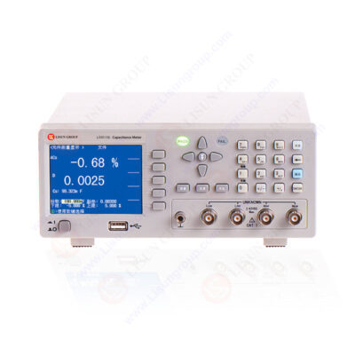
LS6515EN Capacitor meter
A deeper understanding of the working principle of capacitor meter:
The capacitor meter directly measures the capacitive current from the secondary side of the power distribution PT, which makes the test safe, simple and fast, so that the instrument does not need to communicate with the primary side and can accurately and reliably monitoring data, and without making complicated safety measures and waiting for lengthy dispatch command. In addition, the capacitor meter injects the harmonic test signal at the PT’s open triangular junction, not only will not cause any influence to the relay protection and PT itself, but also avoids the 50Hz power frequency interference signal, the output end withstands the AC voltage of 100V, the system has single-phase grounding fault, and will not damage the PT and tester, making the test results more accurate and reliable.
Measurement method of capacitor meter:
This introduces the measure capacitance method of fixed capacitors from 10pf to 001uF. First of all, check the capacitors below 10pf, which can be qualitatively checked using the R * 10k gear of the universal meter, to determine whether there is leakage, internal short circuit or breakdown phenomenon of the capacitor; secondly, 10pf to 001uF fixed capacitors, universal meter should select R*1k gear, using two transistors (passing current should be small, type such as 3DG6, β value greater than 100), and red, black pens of multi-functional meter, respectively Connected to the emitter and collector of the bi-directional tube, to determine whether there is a charging phenomenon, and then determine its quality.
Read the full article
0 notes
Text
Digital relative humidity sensor
My studies during the past few months were focused on Resistors, Fixed Resistors, WSL12068L000FEA18, Vishay, Fixed Resistors value and Digital relative humidity sensor.
0 notes
Text
Everything You Need to Know About Digikey Resistors - Technology Org
New Post has been published on https://thedigitalinsider.com/everything-you-need-to-know-about-digikey-resistors-technology-org/
Everything You Need to Know About Digikey Resistors - Technology Org
You’re probably aware that Digi-Key Electronics is a global electronic components distributor known for its wide selection of parts, including an extensive range of resistors.
Two resistors on a PCB. Image credit: gosiak1980 via Pixabay, free license
The truth is that resistors are fundamental components in virtually every electronic circuit, tasked with regulating current flow, dividing voltages, and performing a multitude of other essential functions. Discover more info here https://spectrum.ieee.org/slideshow-a-day-in-the-life-of-digikey.
So, understanding the different types of resistors and their specific applications is crucial for engineers, hobbyists, and professionals working in the electronics field. Digi-Key’s inventory covers a broad spectrum of resistor types, including fixed resistors, variable resistors, resistor networks, and special-purpose resistors, catering to a wide variety of electronic applications.
Fixed Resistors
Three resistors in a breadboard setup. Image credit: Harrison Broadbent via Unsplash, free license
Firstly, you should know that fixed resistors are the most common type found in electronic devices. These components have a predetermined resistance value that does not change over time or due to environmental conditions. Digi-Key offers fixed resistors in various form factors, including through-hole, surface mount, and chassis mount options, with resistance values ranging from fractions of an ohm to several megaohms.
Materials used in fixed resistors can vary, leading to differences in performance characteristics such as tolerance, temperature coefficient, and power rating. When selecting a fixed resistor from Digi-Key, consider the application’s voltage and current requirements to ensure the resistor can handle the expected power dissipation without exceeding its maximum ratings. Learn more on this page.
Variable Resistors
Variable resistors, or potentiometers, allow for the adjustment of resistance values within a specific range. These components are crucial for applications requiring fine-tuning of circuit parameters, such as volume controls in audio equipment or sensitivity adjustments in sensors.
Digi-Key’s selection includes both rotary and slide potentiometers, trimmers for circuit board mounting, and rheostats for handling higher power applications. When choosing a variable resistor, it’s important to consider the total resistance, adjustment range, physical size, and power rating to ensure compatibility with the intended application.
Resistor Networks
Resistor networks, also known as resistor arrays, consist of multiple resistors integrated into a single package. These components are ideal for use in applications requiring matched resistor values, such as voltage dividers or digital-to-analog converters.
Digi-Key provides resistor networks in various configurations, including isolated, bussed, and dual-terminator types, to accommodate different circuit designs. Resistor networks help streamline circuit layouts, reduce board space, and simplify assembly processes, making them a practical choice for densely packed electronic devices.
Meeting Unique Needs
Beyond standard resistive components, Digi-Key also offers special-purpose resistors designed for specific applications. This category includes current sense digikey resistors for precise current measurement, thermistors for temperature sensing, and varistors for transient voltage suppression.
Each type of special-purpose resistor has unique characteristics tailored to its specific function, such as low resistance values for minimal power loss in current sense resistors or negative temperature coefficients for thermistors. When selecting these components, understanding the application’s specific requirements is critical to ensure optimal performance and reliability.
Tips for Finding the Right Resistor
Navigating Digi-Key’s expansive inventory to find the perfect resistor for your project can be a breeze with the right approach. Given the critical role that resistors play in electronic circuits, choosing the right one is paramount to the success of any project.
Here are some tips to help you efficiently sift through Digi-Key’s selection and pinpoint the resistor that best fits your needs:
Define Your Requirements Clearly
Before diving into Digi-Key’s inventory, have a clear understanding of your project’s specific requirements.
This includes knowing the resistance value, power rating, tolerance, and temperature coefficient needed for your application. Consider the environment in which the resistor will operate, such as high-temperature conditions or exposure to high levels of moisture, as these factors can influence the type of resistor best suited for your project.
Use the Advanced Search and Filtering Tools
Digi-Key’s website is equipped with sophisticated search functionalities that allow you to narrow down your options based on various parameters.
Once you’ve defined your requirements, utilize these tools to filter results by resistance value, tolerance, power rating, and other relevant specifications. This can significantly reduce the time spent searching for the right component among thousands of options.
#analog#applications#approach#Arrays#audio#board#change#devices#diving#electronic#electronic devices#Electronics#engineers#Environment#Environmental#equipment#filter#form#Fundamental#Global#Hardware & gadgets#IEEE#it#Learn#life#materials#moisture#networks#One#Other
0 notes
Text
Debug Any Electronic Circuit in Simple Steps
Debugging and Troubleshooting are essential skills for any electronic circuit designer. Whether you are working on a simple or complex project, you may get in issues with the passive and active elements in your circuit, such as resistors, capacitors, transistors, and op-amps. However, when glitches occur, debugging becomes a crucial skill for engineers and hobbyists. In this article, we will show you how to identify and fix some in circuit problems with these debugging and troubleshooting techniques.
We will discuss on the following 7 techniques which you should used to debug an Electronic Circuit:
Visual Inspection
Power supply requirements
Examine the passive elements
Examine the active elements
Use a breadboard and a prototype board for debugging
Use simulation software and debugging tools
Documentation and Notes
7 Techniques to Debug an Electronic Circuit
Visual Inspection of Circuit and Circuit Diagram
Start with a thorough visual inspection of the circuit board. You should refer to your circuit diagram and implemented circuit to check whether all the connections are made properly. Look for any obvious signs of damage, loose connections, or burnt components. Check for solder joints that may be poorly connected or shorted. A magnifying glass can be handy for spotting minute details that may be overlooked.
Power Supply Requirements
Check if the power supply you provide is sufficient for the circuit or device to operate. Ensuring the power supply requirements are fulfilled is an important step in debugging any electronic circuit. Ensure that the power supply is delivering the correct voltage and current to the circuit. Use a multimeter to measure the voltage at various points in the circuit. Abnormal readings would indicate a power supply issue, such as a faulty regulator or a short circuit.
Examine The Passive Elements
Passive components, which operate without the need for external power, come with elements like resistors, capacitors, and inductors. Evaluate these components by using a multi-meter or an ohmmeter to gauge their resistance, capacitance, or inductance. Utilize a continuity tester to verify the absence of short circuits or open circuits. You should check the recorded measurements with the values you outlined in your circuit power calculation or datasheet. If any problem arises, either you can change the defective component or check for any loose or impaired connections.
Examine The Active Elements
Active components, uses external power for operation, include elements like transistors, op-amps, and integrated circuits. If your circuit has these components then you have to debug them using a multimeter or an oscilloscope to measure their input and output voltages and currents. Additionally, a logic probe or a logic analyzer can also be utilized to examine their digital signals. Check the recorded values with the projected values provided in your circuit power calculation or datasheet. If any issue occurs either substitute the defective component or look for any biasing, feedback, or stability issues.
Using A Breadboard And A Prototype Board For Debugging
A breadboard and a prototype board serve as the best way in the diagnosis and resolution of circuit issues. A breadboard comes with holes and metal contacts, facilitating the effortless insertion and removal of components. You can easily make a small circuit from your main circuit on a breadboard and test if it is working fine. On other hand, a prototype board is equipped with copper traces and pads, offering the capability to solder components permanently. These tools enable you to build and debug your circuit easily, and make the changes required in PCB as fast as possible.
Using Simulation Software (Like Proteus) For Debugging
Simulation software and diagnostic tools like Proteus, Eagle, National instruments, etc, stand out as the best instruments for pinpointing and resolving circuit-related debugging. Simulation software helps to build the circuit and simulate its working in your PC, you can implement everything in these simulation software without any power hazard. Simulation software uses algorithms to model and simulate the behavior of your circuit and its components. You can see real time working of your circuit and take readings without implementing it on the hardware. You can also use diagnostic tools which enable the monitoring and control of variables and parameters within your circuit and components through software commands and breakpoints.
Maintaining Debug Documentation and Notes
Maintain detailed documentation of your debugging process. Maintaining documentation of your debugging process is an important step so that you can check in future if any problem occurs in the circuit. This document will help you guide on debugging and will save a lot of time in future testing. Record the steps taken, measurements, and any findings. This documentation not only aids in tracking progress but also serves as a valuable reference for future troubleshooting.
Conclusion
In conclusion we would suggest you to always follow the above discussed 7 steps if you want to implement a debugging process in your organization. Debugging electronic circuits requires a systematic approach, combining theoretical knowledge with practical skills. By following these steps and leveraging the right software and hardware tools, you can identify and resolve issues efficiently and can ensure the optimal performance of your electronic circuits. Remember to stay patient and persistent – debugging is often a process of finding and elimination, leading you closer to a successful running circuit. Happy debugging!.
At Campus Component, the best electronic components online store you can get top-quality electronic components, cutting-edge debugging tools, and expert technical support. Whether you need resistors, capacitors, oscilloscopes, multimeters, etc or guidance on intricate debugging processes, Campus Component is there!
0 notes
Text
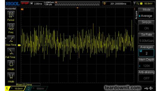
Review, teardown, and testing of LRS-150-24 Mean Well power supply
The LRS-150-24 power supply can operate from a 100–120 volt or 200–240 volt AC network. The manufacturer states it provides an output current of up to 6.5 amperes at 24 volts. The supply measures 5¾ × 3¾ × 1¼ inches (145 × 95 × 30 millimeters), made on a fiberglass printed circuit board fixed to the base's case. The top cover is perforated in a honeycomb pattern. The case and cover are both made of aluminum.
The board is put together neatly, with no visible defects. The components are arranged evenly, and soldering was done with a no-clean flux. Absolutely nothing dangles or rattles in the assembly.
No noises of any sort were noticed during the operation of the power supply.
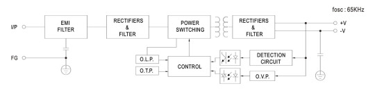
The power supply uses a flyback circuit without PFC.
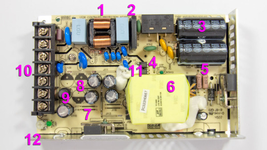
The input voltage is supplied to the input node: RF interference filter (1), a pulse surge limiter (varistor), then the voltage goes to the diode bridge (2) and two input electrolytic capacitors (3). The input voltage selector is also located here. Flyback, built on a MW03A controller (4, installed on the back side of the board) and a power switch (5) on a N-channel MOSFET transistor MMF60R290P. Unfortunately, there is no information about the controller on the Internet. The transistor has a channel resistance of 0.29 ohms at 650 volts and 13 amps. The transformer (6) is entirely covered by the casing, so it is unclear what core material is used. The output rectifier (7) is built using a Schottky diode HBR20150 in a TO-220F package screwed to the side wall and covered with casing. It is basically dual 150V 10A diodes connected in parallel. After the diode there are four output electrolytic capacitors (8) and an additional LC filter. Here (12), there is a small output voltage indicator (green LED) and a regulator (tuning resistor) for adjusting the output voltage. Input and output circuits are connected through a shared screw 7-terminal block (10). 3 terminals for the input line, neutral, and ground wires, and 2 in parallel for common and +24V output.
The main electrolytic capacitors are designed for operating temperatures up to 220°F (105°C), Rubycon. Two optocouplers (11) are installed in the feedback circuit, most likely with phototransistors transmitting control signals from the low-voltage output to the high-voltage input side.
The board has a few cutouts to increase the dielectric strength between the high-voltage and low-voltage sides of the circuit.
The picture shows that the board has three unused spots for storage output capacitors (8), most likely used in the other power supplies of the same series but with different output voltages.
Test conditions
Most tests use metering circuit #1 (see appendices) at 80°F (27°C), 70% relative humidity, and 29.8 inHg pressure.
The measurements were performed without preheating the power supply with a short-term load unless mentioned otherwise.
The following values were used to determine the load level:

Output voltage under a constant load

The high stability of the output voltage should be noted.
Power-on parameters
Powering on at 100% load
The power supply is turned off at least 5 minutes before the test, with a 100% load connected.
The oscillogram of switching to a 100% load is shown below (channel 1 is the output voltage, and channel 2 is the current consumption from the grid):
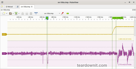
The picture shows three distinguishable phases of the power-on process:
The pulse of the input current charging the input capacitors when connected to the grid has an amplitude of about 7.5 A and a duration of 2 ms.
Waiting for the power supply control circuit to start for about 100 ms.
(Output Voltage Rise Time) Starting the converter, increasing the output voltage, and entering the operating mode) is 8 ms.
(Turn On Delay Time) The entire process of entering the operating mode from the moment of powering on) is 119 ms.
(Output Voltage Overshoot) Output voltage overshoot is absent; the switching process is aperiodic.
Powering on at 0% load
The power supply is turned off at least 5 minutes before the test, with a 100% load connected. Then, the load is disconnected, and the power supply is switched on.
The oscillogram of switching to a 0% load is shown below:
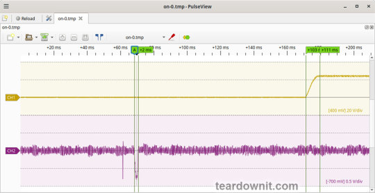
The picture shows three distinguishable phases of the power-on process:
The pulse of the input current charging the input capacitors when connected to the grid has an amplitude of about 7 A and a duration of 2 ms.
Waiting for the power supply control circuit to start for about 103 ms.
(Output Voltage Rise Time) Starting the converter, increasing the output voltage, and entering the operating mode) is 8 ms.
(Turn On Delay Time) The entire process of entering the operating mode from the moment of powering on) is 111 ms.
(Output Voltage Overshoot) Output voltage overshoot is absent; the switching process is aperiodic.
Power-off parameters
The power supply was turned off at 100% load, and the input voltage was nominal at the moment of powering off. The oscillogram of the shutdown process is shown below:

The picture shows two phases of the shutdown process:
(Shut Down Hold Up Time) The supply continues to operate due to the input capacitors holding charge until the voltage across them drops to a certain critical level at which maintaining the output voltage at the nominal level becomes impossible is 31 ms.
(Output Voltage Fall Time) Reduction of the output voltage, stopping voltage conversion, and accelerating the voltage drop is 21 ms.
(Output Voltage Undershoot) Output voltage undershoot is absent, and the shutdown process is aperiodic.
Ripple voltage and current
100% load
The diagram of the current draw from the grid at 100% load is shown in the oscillogram below. The amplitude of the current is about 7.5 A:
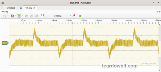
Low-frequency output voltage ripple is under 30 mV (see the oscillogram below):

Output voltage ripple at the converter frequency is under 30 mV (see the oscillogram below):

75% load
Output voltage ripple at the converter frequency is under 30 mV (see the oscillogram below):
Low-frequency output voltage ripple is under 30 mV (see the oscillogram below):

50% load
Output voltage ripple at the converter frequency stays below 10 mV; see the oscillogram (11):
10% load


0% load
No-load current consumption was measured with a multimeter, which is 60 mA RMS.
(Power Consumption) The first assumption of excessive standby power draw of more than 7 W is wrong since the current in this mode is predominantly reactive. Indeed, the input filter in the circuit contains two capacitors with a capacitance of 0.68 μF each; these low-frequency capacitors are connected in parallel, i.e., an equivalent capacitance of 1.36 μF is connected to the input terminals. A simple calculation shows that the current through these capacitors should be equal to Ic=120×2×pi×60×1.36e-6=61.5 mA. A slight difference from the measured value can be explained by the deviation of the actual parameters from their nominal values and measurement error.
Measuring the exact active power consumption at a 0% load with a basic set of instruments (oscilloscope, multimeter, etc.) is impossible.
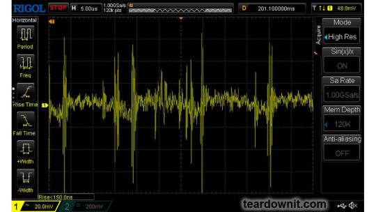
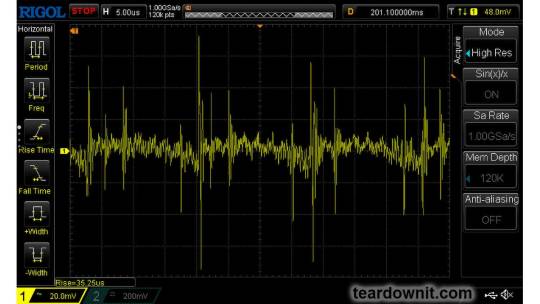
Output voltage ripple at the converter frequency is under 20 mV (see the oscillogram below):

The amplitude of low-frequency output voltage ripples is about 25 mV (see the oscillogram below):

Dynamic characteristics
A mode with periodic switching between 50% and 100% load was used to evaluate the dynamic characteristics. The process oscillogram is shown below (17):

It is evident that the supply’s response to loading changes is close to aperiodic, and there is no overshoot, which indicates a good stability margin. The magnitude of the response to load changes is within 200 mV.
Overload protection
The claimed protection type is "hiccup mode, recovers automatically after fault condition is removed". This was confirmed during testing. When a short circuit occurs, the power supply periodically tries to turn back on and, if the overload is still present, turns off again until the next attempt. This operating mode reduces energy losses and heating during overload. Still, it does not allow the parallel connection of multiple power supplies with a common output.
The output current for the overload protection to kick in is 8.5 A.
Input circuit safety assessment
(Input discharge) Safety assessment is based on the discharge time constant of the input circuits when disconnected from the grid; the value is 0.384 s. This means that when operating on a 120 V input voltage, the time required to discharge the input circuits to safe values (<42 V) will be 0.61 s:

Important: The result is valid for this particular power supply unit; it was obtained for testing purposes and should not be taken as a safety guarantee.
Thermal modes
When operating with no load connected, no component overheating had been noticed.
When operating under load, the input diode bridge heats up most noticeably.
With a load of 90% and the top cover closed, the case heats up to approximately 200°F; the hottest spot is located in the area of the diode bridge rectifier.
With a load of 95% and the lid closed, the case temperature reaches 230°F:

The temperature of the bridge rectifier itself is a dangerous 250°F:

Somewhere around these load values, the power supply goes into a pulse-power-limiting mode and remains in this state either until the load drops or until it cools down. Then this 'heat up', 'limit power', 'cool down', and 'turn back on' cycle repeats.
Other things to consider:
Hot summer weather will decrease the maximum sustainable power output this supply can provide even more.
The tests were conducted with unobstructed air access to the housing for cooling; any changes may increase the heating.
This means that the power supply cannot handle its rated load for a prolonged period with no forced ventilation, and the load should be limited to 5.5 or even 5.0 A.
Conclusions
The reviewed power supply unit has characteristics generally consistent with those declared by the manufacturer, except for the long-term output power, which should be around 120 W.
The build quality is decent; no components clearly unsuitable for the general application, power draw, current, voltage, or temperature were found in the circuit.
The stability of the output voltage should be especially noted.
0 notes
Text
Electronic Resistors Market Analysis, Dynamics, Players, Type, Applications, Trends, Regional Segmented, Outlook & Forecast till 2033
The global electrical resistors market size reached USD 6.03 Billion in 2023. expects the market to reach USD 10.60 Billion by 2033, exhibiting a growth rate (CAGR) of 5.8% during 2024-2033.
The competitive analysis of the Electronic Resistors Market offers a comprehensive examination of key market players. It encompasses detailed company profiles, insights into revenue distribution, innovations within their product portfolios, regional market presence, strategic development plans, pricing strategies, identified target markets, and immediate future initiatives of industry leaders. This section serves as a valuable resource for readers to understand the driving forces behind competition and what strategies can set them apart in capturing new target markets.
Market projections and forecasts are underpinned by extensive primary research, further validated through precise secondary research specific to the Electronic Resistors Market. Our research analysts have dedicated substantial time and effort to curate essential industry insights from key industry participants, including Original Equipment Manufacturers (OEMs), top-tier suppliers, distributors, and relevant government entities.
Receive the FREE Sample Report of Electronic Resistors Market Research Insights @ https://stringentdatalytics.com/sample-request/electronic-resistors-market/12545/
Market Segmentations:
Global Electronic Resistors Market: By Company
• Yageo
• VISHAY
• Bourns
• TT Electronics
• ROHM
• Viking
• Cyntec
• Susumu
• Panasonic
• Samsung
• Ohmite
• KOA Speer
• Crownpoc
• TOKEN
• TA-I
• Walter
• Caddock
Global Electronic Resistors Market: By Type
• Fixed Resistor
• Variable Resistors
Global Electronic Resistors Market: By Application
• Industrial Electricity
• Computers and Peripherals
• Automotive
• Consumer Electronics
• Commercial Electrical
• Household Electrical
• Other
Regional Analysis of Global Electronic Resistors Market
All the regional segmentation has been studied based on recent and future trends, and the market is forecasted throughout the prediction period. The countries covered in the regional analysis of the Global Electronic Resistors market report are U.S., Canada, and Mexico in North America, Germany, France, U.K., Russia, Italy, Spain, Turkey, Netherlands, Switzerland, Belgium, and Rest of Europe in Europe, Singapore, Malaysia, Australia, Thailand, Indonesia, Philippines, China, Japan, India, South Korea, Rest of Asia-Pacific (APAC) in the Asia-Pacific (APAC), Saudi Arabia, U.A.E, South Africa, Egypt, Israel, Rest of Middle East and Africa (MEA) as a part of Middle East and Africa (MEA), and Argentina, Brazil, and Rest of South America as part of South America.
Click to Purchase Electronic Resistors Market Research Report @ https://stringentdatalytics.com/purchase/electronic-resistors-market/12545/
Report includes Competitor's Landscape:
➊ Major trends and growth projections by region and country
➋ Key winning strategies followed by the competitors
➌ Who are the key competitors in this industry?
➍ What shall be the potential of this industry over the forecast tenure?
➎ What are the factors propelling the demand for the Electronic Resistors?
➏ What are the opportunities that shall aid in significant proliferation of the market growth?
➐ What are the regional and country wise regulations that shall either hamper or boost the demand for Electronic Resistors?
➑ How has the covid-19 impacted the growth of the market?
➒ Has the supply chain disruption caused changes in the entire value chain?
Customization of the Report:
This report can be customized to meet the client’s requirements. Please connect with our sales team ([email protected]), who will ensure that you get a report that suits your needs. You can also get in touch with our executives on +1 346 666 6655 to share your research requirements.
About Stringent Datalytics
Stringent Datalytics offers both custom and syndicated market research reports. Custom market research reports are tailored to a specific client's needs and requirements. These reports provide unique insights into a particular industry or market segment and can help businesses make informed decisions about their strategies and operations.
Syndicated market research reports, on the other hand, are pre-existing reports that are available for purchase by multiple clients. These reports are often produced on a regular basis, such as annually or quarterly, and cover a broad range of industries and market segments. Syndicated reports provide clients with insights into industry trends, market sizes, and competitive landscapes. By offering both custom and syndicated reports, Stringent Datalytics can provide clients with a range of market research solutions that can be customized to their specific needs.
Reach US
Stringent Datalytics
+1 346 666 6655
Social Channels:
Linkedin | Facebook | Twitter | YouTube
0 notes
Text
How valve amplifier repairs improve audio quality?
The timeless charm of valve amplifiers endures in the ever-changing field of audio technology, captivating both music lovers and audiophiles. These amplifiers are time-tested and renowned for their rich, warm sound signature and retro appeal. To preserve or even improve their audio quality, valve amplifiers could need periodic repairs, just like any other complex piece of machinery. We will examine how valve amplifier repairs can greatly improve audio quality in this blog post, going into the complex mechanisms that make these repairs an essential part of maintaining and enhancing sonic brilliance.

Repairs' effect on audio quality
Vacuum tube aging is one of the most prominent causes of a decrease in audio quality. These tubes may become less effective with time, which would result in a loss of warmth and clarity. A competent technician can revitalise a valve amplifier with a methodical valve replacement procedure. Switching to premium tubes can extend the amplifier's life and improve the clarity and depth of the sound it generates.
Within the amplifier, capacitors are essential for filtering and balancing the electrical impulses. Capacitors may lose some of their effectiveness with age, which can cause distortion and noise to appear in the audio output. High-quality, contemporary capacitors can replace obsolete ones, improving signal integrity lowering distortion and eventually raising the level of audio quality.
Essential parts that regulate the electrical current flow in the amplifier circuit are resistors. They may deviate from their initial values over time, which could impact how well the amplifier works. Expert technicians are capable of locating and swapping out malfunctioning resistors, guaranteeing that the amplifier functions within its intended specifications. This may improve performance overall in addition to restoring the original acoustic qualities.
A well-done repair may include signal route optimisation in the amplifier circuit. Maintaining a clear and continuous audio signal flow may entail cleaning or replacing input and output jacks. Furthermore, signal deterioration can be removed by fixing solder joints and connections, which will produce a more accurate copy of the original audio.
Conclusion
In addition to fixing problems, valve amplifier repairs open the door to the complete potential of this classic audio equipment. Expert technicians may restore a valve amplifier to its former glory and allow it to produce sounds that are on par with or even better than it did by carefully identifying and resolving problems like resistor drift, capacitor degradation, and tube attrition. The warmth and character of valve amplifiers are still valued by audio fans, and in the digital age, maintaining and enhancing the enchantment of analogue sound requires skilful repairs. For more information about valve amplifier repair, contact us today.
Disclaimer: This is generic Information & post; content about the services can be changed from time to time as per your requirements and contract. To get the latest and updated information, contact us today or visit our website.
0 notes
Text
Understanding Resistor Networks: Exploring Fixed Film Types and Where to Buy Electronic Parts Today
Resistor networks play a crucial role in electronic circuits, providing resistance to control the flow of electric current. Among the various types available, fixed film resistors are widely used for their stability and reliability. In this blog post, we will delve into the world of resistor networks, focusing on fixed film types, and explore where you can conveniently buy electronic parts today.
Resistor Networks: An Overview Resistor networks consist of multiple resistors connected together, often in a single package. These networks offer advantages in terms of space efficiency and simplified circuit design. Fixed film resistors, a common type within resistor networks, are constructed with a thin film of resistive material. This film is deposited onto a ceramic substrate, providing a stable and precise resistance value.
Understanding Fixed Film Resistors Fixed film resistors are known for their accuracy, low noise, and reliability. The thin film technology allows for precise control of resistance values, making them suitable for various applications, from consumer electronics to industrial equipment. The fixed nature of these resistors means that their resistance values remain constant over time and under varying environmental conditions.
Applications of Resistor Networks Resistor networks find applications in diverse electronic circuits, such as voltage dividers, signal conditioning, and feedback networks. Their compact design makes them ideal for use in integrated circuits and densely populated circuit boards. Fixed film resistors within these networks contribute to the overall stability and performance of electronic devices.
Where to Buy Electronic Parts Today If you're in need of resistor networks, fixed film resistors, or any other electronic components, it's essential to find a reliable source. One reputable option is NSN Parts Lookup, a leading online platform offering a wide range of electronic parts. With a user-friendly interface and a vast inventory, NSN Parts Lookup simplifies the process of sourcing quality components for your projects.
Visit NSN Parts Lookup Today and explore their extensive catalog of electronic parts. Whether you're a hobbyist or a professional engineer, finding the right resistor networks and fixed film resistors has never been easier.
Conclusion Resistor networks, especially those incorporating fixed film resistors, are integral to the functionality of electronic devices. Understanding their properties and applications is crucial for designing robust circuits. When it comes to sourcing electronic parts, consider NSN Parts Lookup for a hassle-free and reliable experience. Buy electronic parts today and embark on your journey to building innovative and efficient electronic systems.
0 notes
Text
Wireless rf circuit
Next year, I will concentrate on learning about the best Capacitors, Tantalum Capacitors, 594D476X9016C2T, Vishay. I will also focus on Wireless rf circuit and Fixed value resistor.
0 notes
Text
Common faults and problems of automation equipment
With the popularity of non-standard automation and the maturity of technology, more and more enterprises have adopted non-standard automation equipment. When the automation equipment suddenly fails to work, or the working sequence fails, fault diagnosis must be carried out.

The common problems of automation equipment are as follows:
1. Open circuit or open circuit: The disconnection or open circuit of the output of the instrumentation equipment and the input circuit of the feedback signal during the use of the machine is a general fixed fault.
2. Power failure: Power failure is a static failure. This fault is mostly caused by open circuit of the power line or ground wire, wrong wiring or poor contact. It may also be caused by the input voltage of the instrument equipment or the circuit board's own power supply component exceeding the allowable deviation, and the output of the power supply component's own circuit failure. The voltage exceeds the allowable deviation (such as abnormal increase or decrease of voltage).
3. Failure of passive components: loose end caps of resistors often lead to open circuits, open circuits or open circuits of capacitors, changes in capacitance or resistance values, and burnout of resistors. Changes in the resistance value cause failures such as fuzzy logic values, and changes in the capacitance value may cause failures such as poor decoupling, changes in the frequency of the oscillator, and failure to start equipment such as motors.

4. Poor power supply decoupling: This type of fault is mainly caused by the interference waveform (or signal) being superimposed on the normal waveform. This kind of interference can be suppressed by a large-capacity filter capacitor and a ceramic capacitor with good high-frequency performance.
5. Interference: The signal on one line is coupled to another line due to induction, which often causes interference in the product. The size of the crosstalk signal is proportional to the line spacing and signal frequency. If the strong current and the weak current are mixed in the same cable, the signal of the weak current will be bad or even burn the signal channel.
6. Unreliable auxiliary equipment or devices: Unreliable performance of nodes or contactors, mechanical failures and other equipment or devices will cause poor reliability.
7. PCB failure: PCB power supply short circuit or open circuit, jumper address error, especially highly integrated IC chips due to manufacturing defects, overheating and other reasons may interact and cause transient failure or permanent damage.

8. Poor contact: Poor contact occurs frequently, similar to an open circuit, but it is accidental, and it is extremely difficult to detect the fault at the initial stage. The common causes of poor contact are: loose plug-in, poor welding, oxidation of the contact surface, loose terminal wiring (sometimes caused by large environmental vibrations), and elastic degradation of the contact reed.
9. Poor insulation: Poor insulation is often ignored by the staff because of its small impact on the machine. Poor insulation caused by surface treatment and processing problems on the circuit board will further lead to signal cross-wiring and leakage, making the circuit board unstable or even unable to work normally.
10. Poor shielding: Poor shielding often causes related faults such as signal distortion or distortion.

11. Component aging and poor quality: equipment has a certain service life. When the equipment works longer than the service life, each component will enter the attenuation period. Therefore, the functional characteristics of the component will be greatly reduced, and the failure rate will increase. Poor quality of the component will also cause a high failure rate.
0 notes
Last Seen Blogs

sainthill
𝕊𝕒𝕚𝕟𝕥ℍ𝕚𝕝𝕃.

silentwhispersintheforest
Silent Whispers in the Forest

oneeyecatnamedkay
Abode of OneEyeCat

2alldapear
Nique Baby ✨

alcinassugarbby
Vampy Wifey Supremacy