#Fottery
Text
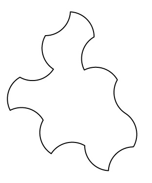
Circle designs
From a Mastodon toot "This is how a real data scientist drinks coffee"

The image is by Javier Jaén. It looks very real but it must be computer-generated. I wondered if I could make it real and used my work on Eulerian circuits to create a spiral-printed version (sans handles). Intersecting circles create a Eulerian circuit since every intersection is even, but the path is not so obvious. The code in JavaScript computes the intersections and the arcs between intersections, constructs a graph and uses the Hierholzer algorithm to find a path.
This is the Gcode generated from Fottery
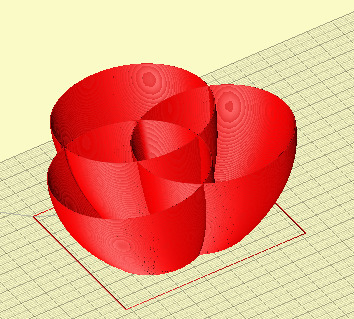
and here printed in white PLA
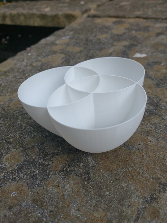
The cup profile is adapted to make it easier to print.
Next step is to make it in ceramic.
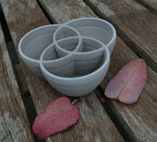
Printed in a stoneware clay on my Eazao Zero. Not as prefect as the computer-constructed image, just as useless as a cup but it is a real object (and will look better once fired and glazed).
2 notes
·
View notes
Text
Non sbagliatevi
Esser di sinistra è in piccolissima minoranza il desiderio di cummannari e fotteri il prossimo per occuparsi del “loro benecomune” che evidentemente conoscono meglio degli stessi. Una assoluta minoranza.
La vastissima maggioranza della gente di sinistra sta lì perché GODE a sentirsi dominata, gestita, oppressa, comandata, direzionata nei più minimi dettagli.
3 notes
·
View notes
Text
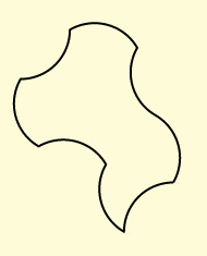
The 'Spectre' monotile
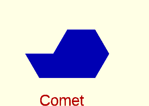
The recently discovered Hat and Turtle monotiles needed to use a reflected version of the tile in aperiodic tiling and this seemed a bit untidy. Although I had used OpenScad to generate the continuum of tiles from Comet to Chevron via Hat, I hadn't appreciated that 'Turtle' lay in the continuum and created a separate continuum for that tile with a different perimeter. Doh!
In my parametrisation, the continuum is generated by varying the kite semi-angle A from 0 to 90, with the two side lengths respectively a=cos(A) and b=sin(A) .
This OpenSCAD function generates the tile perimeter for a given angle A:
function monotile(r,A) =
// r is the radius of the base hexagon
// returns perimeter as a sequence of [side,internal angle]
let (a = r * cos(A) ,b = r * sin(A) )
[[a,180],[a,120],[a,270],[b,120],[b,90],[a,120],[a,270],[b,120],
[b,90],[a,240],[a,90],[b,240],[b,90],[a,120]];
where these are the special case (together with the Smith et al parameterisation)
A=0 : Chevron Tile(0,1)
A=30 : Hat Tile(1, sqrt(3))
A=45 : Equilateral Tile (1,1)
A=60 : Turtle Tile(sqrt(3),1)
A=90: Comet Tile(1,0)
It turns out (that phrase covers a huge amount of work described in the most recent paper) that the Equilateral tile (A=45) is quasi-aperiodic in that it is aperiodic only if reflections are forbidden.
To modify the tile to prevent reflections, one approach is to replace the straight sides with arcs which alternate left and right. Since the tile is equilateral (noting that the long side is composed of two co-lateral short sides) , a common arc angle yields arcs of common curvature
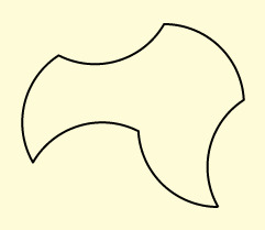
It's easy to see how the resultant tile got its nickname 'Spectre'

although we might be calling it 'Elephant' if the arcs had been oriented in the opposite direction:
This version of the tile was generated from the perimeter by a JavaScript tool developed for ceramic design which uses a form of Turtle language. It's the 'Spectre' function in the list of functions. The Arc angle here is 90 degrees.
OpenSCAD
The online tool generates the perimeter as a sequence of points, intended for copying into the Fottery tool to create the Gcode to print ceramic objects. The sequence is in the same format as that used to define a polygon in OpenSCAD so a minimal script looks like:
thickness=4;
perimeter = {paste the sequence here };
linear_extrude(height=thickness)
offset(delta=-1)
polygon(perimeter);
[I should really implement this version of the Turtle language in OpenSCAD so resolution is determined in the OpenSCAD script]
The negative offset here allows for slightly excess filament width in a 3D printed part. (you still have to clean off any 'elephants foot'). Offset would be positive for laser-cutting to allow for the kerf.

Diversion
The JavaScript tool also generates arced versions of the other tiles in the continuum from Comet to Chevron. These two periodic tiles are also equilateral so all sides have the same curvature. These are rather pleasing shapes to use for tesselation:
The number of sides is 8 for the Comet, 6 for the Chevron, corresponding to the 8 a sides and 6 b sides in the common perimeter.
Further reading
'A chiral aperiodic monotile' David Smith, Joseph Samuel Myers, Craig S. Kaplan, Chaim Goodman-Strauss https://arxiv.org/abs/2305.17743
Aperiodical : Now that's what I call an aperiodic monotile
Craig Kaplan -Mastodon Thread
Craig Kaplan : Blog
0 notes
Text
Texture on printed pots

So far I’ve focused my work on 3D printed ceramics on the form of the pot rather than the texture of the surface. Much of the work I see from others has it the other way round: put complex textures on simple round vase shapes.
In summer, my life turns from messing with 3D printing to sailing. I’ve seen a lot of water in my time and am always fascinated by the wave patterns. These are particularly interesting when the water is quite smooth but mottled by two wave trains coming from different directions. These give rise to interference patterns, with wave heights adding in some places to increase the height of crests or depths of troughs but in other places cancelling each other out. Often two main wave trains can be seen with a third with a shorter wavelength where wind is rippling the surface.
This clip shows the effect of waves crossing their own reflection.
[My interest was stirred when as a schoolboy in New Zealand, we were lucky to be taught Nuffield physics (or was it PSSC physics?). The ripple tank was one of my favourite pieces of equipment which allowed different kinds of wave interactions to be created.]
In seaching for ways of modulating the surface of a 3D printed vase, I tried to model this situation with two or more sine waves defined by an amplitude and frequency running at an angle to the horizontal. The interaction between a wave and its reflection can be modeled with a wave at angle A to the horizonal whose amplitude at each point is added to that of another wave at angle -A . The Sum Sine perimeter modulation function in Fottery supports up to 3 sine waves. Natural water waves are more complicated than pure sine waves but I think it captures the essence.
I prototype these patterns in clear PLA . I like the way light plays on these surfaces and hope I can get a similar effect on a glazed pot.

2 notes
·
View notes
Text
Handles on mugs
An obvious object to print with the 3D clay printer would be a mug, Made with the printer, a mug is freed from the constraints of a thrown pot and doesn’t have to be round, but it does have to be drinkable from. You also need to be able to hold it when it contains a hot drink, hence the need for a handle. I’ve seen various attempts to include a handle in a 3D print, but it’s not easy in clay. A mug with a graspable handle has a hole in the cross section and can’t be printed as one continuous path. In addition, to make a usable handle will involve steep angles and unsupported sections which would need additional support structures. So printing a handle is very problematic.
A thrown pot or one made with slabs has the same problem. Typically this is solved by making the handle as a separate object and attaching it to the mug in the hard leather stage of drying, when both are rigid enough to handle but soft enough for scoring and joining with slip.
Benjamin Buchenot has very helpful video explaining the design problem and how to make and attach a handle to a mug.
However, for the thin-walled pots coming off the printer, attaching a handle is going to be a rather delicate. A handmade, perhaps slighly misshapen handle may also look incongruous against the precision of a printed mug.
The problem of holding a hot mug is solved in plastic mugs in a different way. Typically these are double walled, which has the added advantage of keeping the contents hot. Printing a double-walled mug with a outer and separate inner and a gap between them could be done but not as a continuous extrusion.
I printed this bowl - planter yesterday. It was designed in Fottery, my own design and gcode tool. Printed in Sibelco White Clay which is heavily grogged - 30% 0.5mm. Mixed to a syringe pressure of about 3kg it extruded fine and seems to have better green strength but the finish is quite rough.

The pot uses a family of Reuleux curves. These are generalisations of the Reuleux triangle, a surprising curve you can use as the profile of a roller since it has the property of constant width. Bending the rules to include a fractional number of sides generates this curve with seven sides over two rotations.
In the bowl design, there is an added rotation between the top and bottom layers so the interpolation between the layers results in a flared twist.
This bowl gave me the idea of using this curve for a mug. When holding the bowl in your hand, you are not in direct contact with the liquid inside, though the mug as a whole will warm up through conduction. To make a rim we need to close up the top layer. This creates air pockets but the base could be made with holes to vent the spaces. These are the two layers, red for bottom, blue for top:

Other curves with multiple revolutions could be used. This is a Rose Curve which takes 3 rotations to close.

Here there are two air pockets so no point on the outside is in contact with the hot liquid inside. However this design has more material and will be heavier, although the walls can be quite thin because the object gains rigidity from the cross-linking. To make the lip, I’ve uses a Lame curve with k= 2( ie a circle) but 3 iterations of the curve to allow it to match the Rose curve. The full shape is obtained by interpolated between bottom and top over the height of the mug. A side effect is a thickening of the material through repeated passes at the top (progressive reduction in the extrusion rate might help here).
Another possible design is to have an inner and outer wall, connected by a connecting wall. It’s less obvious here that the object can be printed as a continuous extrusion but it can be. Again the triple-wal wil lmake the mug heavy.

Here are a couple of scaled down bottom-less tests :


So will any of these design work in practice? I’ll print all three designs + a plain cylinder to test. Ive a hand-held infrared thermometer to measure the wall temperature and I can see myself getting distracted into making a temperature recorder!
2 notes
·
View notes
Text
Turtle Paths and Ceramics design
Mathematical functions can create some wonderful, surprising shapes but the reverse, to devise a function to create a given shape, is usually harder, for example a rectangular pot with rounded corners. A 3D design language like OpenSCAD can to this but it's not trivial and difficult to import the result into the Fottery tool. The Inverse Fourier Transform can do this if the original shape is already defined in cartesian coordinates.
An alternative approach is to create a language in which to describe the shape and convert that to a sequence of points.
Cartesian Coordinates and Turtle Paths
Typically we describe a curve as a sequence of [x,y] Cartesian coordinates representing the end-points of straight line seqments. x and y are absolute values in a common coordinate system. This form is easy to convert to a graphical display and to GCode.
In Turtle graphics (1), the curve is defined by relative steps along the curve, from the point of view of a robot turtle drawing the line. Steps are of three kinds: F to move forward an amount and L amd R to turn left or right by an angle. So a rectangle can be described by the sequence of steps:
F 20, L 90, F 10, L 90, F 20, L 90, F 10, L 90
This form is readily converted to Cartesian form.
[this and other images are taken from OpenSCAD where the design was protyped]
Lines and arcs
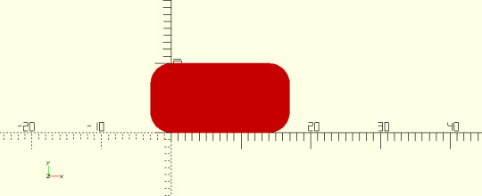
These sharp corners are not suitable for ceramic printing and limit the shapes which can be described. An extension to the language is to add a radius to the turn commands, which would be by defailt 0 for a sharp turn.
F 20, L 90 3, F 10, L 90 3 ,F 20, L 90 3, F 10, L 90 3
where L 90 3 means turn left 90 degrees with a radius of 3.

Note that this has enlarged the rectangle - adding the radius to height and width at each corner. To get back to the original dimensions, I have to adjust the side lengths:
F 14, L 90 3, F 4, L 90 3,F 14, L 90 3, F 4, L 90 3
Yin-Yang
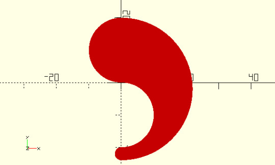
One motivation for this style of Turtle language was to be able to create a Yin-Yang bowl with two identical half bowls so that they nest nicely. The Turtle for one half is
L 180 10, R 180 10, R 180 20, R 180 0

The sharp point isn't really printable but we can increase the radius as long as we increase the outer radius of the outer semicircle as well:
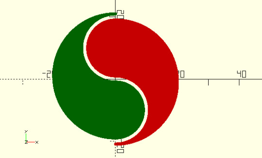
This requires a parametric path :
L 180 a, R 180 a, R 180 2*a+b, R 180 b
where a is the major radius, b the minor radius.
To make a matching pair, we need to account for the wall width by insetting the curve by about half the wall width (or a bit more here to show the matched pair)
Reuleux curves and Triguetra
The reuleux triangle is a constant-width curve composed on three 60 degree arcs. It is expressed in Turtle form as
L 60 r, L 60, L 60 r, L 60 ,L 60 r, L 60
where r is the radius of the arc. The two turns at each corner, one the arc, the other a sharp angle together produce a turn of 120 degrees to get a total turning of 360.
This form is readily generalised to arcs of any angle a :
L a r, L 120-a, L a r, L 120-a,L a r, L 120-a
which in one extreme where a = 120 defines another constant-width curve, the circle. I haven't figured out if all curves with a in the range [120 , 60] are constant width. Further generalization to different numbers of sides and different multiples of 360 yield curves such as the triquerta:
L 180 10,L 60,L 180 10,L 60,L 180 10,L 60
Tricurves
Tim Lexen (2) has researched curved triangles with one convex side and two concave sides, all arcs with the same radius, such that the sum of the arc angles (and hence arc lengths) of the concave sides is equal to that of the convex side. These curves tile in periodic and non-periodic ways. For pottery, bowls in this shape will fit together.
Here the parametric path of a tricurve with a common radius r, a convex angle A and concave angles B and C where B+C=A:
L A r , L 180-C, R B r, L A, R C r, L 180-B
eg where A=108, B=36 C=72:

Implementation
This variant of the Turtle language is implemented in an online tool which incorporates the above functions and allows the curve to be exported to the Fottery tool or as SVG.
I look forward to using some of these curves in ceramics when I get back from sailing in Scotland - with a rather broken computer:(
Turtle graphs was developed by researchers at MIT including the maths educator Seymour Papert in the 1960's and lives on in many variants. See Turtle Graphics by Abelson and DiSessa and Mindstorms by Seymour Papert.
Tim Lexen tricurves https://aperiodical.com/2018/07/bending-the-law-of-sines/
11011110 some posts on arc triangles:
https://11011110.github.io/blog/2021/05/09/arc-triangle-tilings.html
https://11011110.github.io/blog/2021/07/10/angles-arc-triangles.html
1 note
·
View note
Text
Eazao Zero : Progress and notes
I’ve learnt a lot over the past couple of months about the Eazao Zero and clay printing in general. I am very pleased that the printer has performed so well. The only barrier is my knowledge of pottery, access to a kiln and my imagination!
These notes are mainly to gather my experience in one place. I hope they might be useful to others. Do let me know what I’ve missed or got wrong. I’ve included some notes on using Pronterface to control the printer externally.
Local here means Bristol,UK.
Clay
I buy my clay from nearby Hot Clay. I took Jonathan Keep’s guide to clays along when I first went and the technical guy there matched Jonathan’s recipe to this Sibelco Scandi clay with 25% 0.2mm grog. Most of my prints have been made with this clay. I’ve also used this more groggy clay which extruded fine despite its 30% 0.5mm grog and prints have a rough texture, better overhang strength but dry quickly with a short leather stage.
Bats and bed height
I made a number of 9.5 mm thick bats from offcut MDF. These absorb a bit of wetness to help the first layer stick and dry the base of the print well.
I find it useful to have a few sheets of card ready to use as shims under the bat if the nozzle height is a bit high. Light card that I use is 0.2mm thick.
Nozzles
There a number of Luer fittings and I found it difficult to find the ones used. Finally the magic search term seemed to be “Luer Smooth Flow Tapered Dispense Tips” . The sizes of needles and nozzles are I think defined by the Birmingham guage although the colours (for hypodermic needles) dont seem to agree with this table and sizes are slighly different. These are some of the colours and guages
colour, gauge, internal diameter
White 27ga 0.20 mm
Red 25ga 0.25mm
Blue 22ga 0,41 mm
Pink 20ga 0.61 mm
Green 18ga 0.84mm
Grey 16ga 1.2 mm
Olive 14ga 1.55 mm (Easao call this bright green) [metal]
Light Blue? 13 ga 1.8mm
Light Blue 12 ga 2.2 mm (Eazao call this bright blue) [metal]
Orange 11ga 2.4mm
Light Green 10 ga 2.7mm [metal]
8 ga 3.4mm [metal]
Individual packs of larger sizes are available from AliExpress . I now have some Orange 11Ga nozzles for thicker walls.
I’ve mainly used 14ga and some finer work with 16ga. I have been unable to locate 12ga nozzles which are included in the Eazao nozzle selection. It would have been nice if the printer had come with this selection. Nozzles are avaliable in the UK from Adhesive Dispensing and mixed packs are also available on Ebay.
I experimented with a thicker nozzle by cutting down a 1.55 nozzle to about 2mm. This reduced the length by some 6mm and since Marlin doesn’t handle negative z heights, I made some 19mm thick MDF bats to compensate. Still experimenting with this but a proper 12ga nozzle would be better.
I now have some metal nozzles to cover the larger sizes. These have very long barrel which creates friction - perhaps they could be carefully cut done but the edge would not be very clean.
Cartridge
https://www.eazao.com/product/cartridge-for-eazao-zero
You really need more than one so one can be being refilled while the other is being used to print. I havent found an equivalent to this item and the carriage from China is very expensive. Need a local stockist able to buy in bulk.
From the dimensions of the cartridge, with an ID of 49.65mm , a 1 mm section of the tube contains PI * 49.65 * 49.65 / 4 mm^3 = 1936 mm^3 = 1.936 cm^3 (ml) . so 50ml occupies 50 /1.936 =25.825mm which is pretty close to an inch (25.4mm). So a inch ruler, offset about 20mm from the front plate, measures the remaining clay in 50ml units. My Fottery tool estimates the volume of a print so this can be used to see if enough clay is left for a print ( this needs checking!).
Someone on the Facebook group found a near-equivalent tube as the main part of an oil syringe, available in the UK at . The outer thread is just a bit big but can be worke down, whilst the output is a loose fit for the G1/4 thread on the tibe connector.
Feeding tube
As supplied this is a tube with an OD of 10mm and ID of 7mm. https://www.eazao.com/product/feeding-tube/ When I clogged my tube by neglecting to clean it, I looked for a replacement in the UK but could only find clear polyurthane tube as 10x8 from https://www.advancedfluidsolutions.co.uk/ ( PU10/08010mm OD x 8mm ID Metric Polyurethane Flexible Tubing PU Air Pipe CLEAR)
Considering that the cross-sectional area of this tube is 31% ( 8*8)/(7*7) more than the supplied tube this seemed to be a better choice if rigid enough. In practice it has worked fine and allows rather thicker clay with no downside. Should be the recommended tube I think.
Pipe connections
The tube fittings are standard eg https://www.aquatuning.co.uk/water-cooling/fittings/push-in-fittings/208/10mm-g1/4-plug-fitting-bl=
Extruder bearing
I found the bearing https://www.eazao.com/product/f634zz-bearing/ had rusted to the extruder auger. Obviously it needs drying and perhaps oiling if it’s going to be left for any time Finding a new bearing locally wasn’t a problem as this is a standard item F634zz and I found them for a few quid. I damaged the oil seal by stupidly removing it over the auger screw (rather than taking the extruder apart first) but then found this size of seal 4 x 17 x 7 (ID, OD, width) was unavailable in the UK. Eazao found them on Aliexpress and I’ve ordered a couple. I’d included a second extruder in my kickstarter and this came with a spare oilseal.
Cleaning
I’ve got a bit quicker at cleaning up the printer prior to leaving it for a while. My equipment is
a thick dowel rod to push the rubber plunger back out - I find it helps to soak the cartridge for a while if it’s stuck
a large bottle brush for cleaning out the cartridge tube
a thin dowel rod to run through the feeding tube
a small bottle brush attached to a length of curtain wire to drag through the feeding tube
another small bottle brush to clean the extruder and connectors
a nail brush to clean threads and outsides
Direct control of the printer
I use Pronterface to interface with my Prusa 3D plastic printer so that was my first choice of software to control the clay printer directly. Other software is available and Eazao have a useful tutorial on using Repetier.
Connect at a baud rate of 250000
Pronterface sends commands to the Eazao, either from its graphical interface or as typed commands. Movement commands and extrusions are all relative. Pronterface doesn’t know about the mix (unless you send the appropriate commands) so each ‘extruder’ runs separately:
Extruder is Tool 0 - set with T0 (the default)
Putter is Tool 1 set with T1
So each ‘extruder’ can be controlled by first sending the appropriate T code. To move the putter a longer distance than the graphic interface allows, sent a G1 command eg.
G1 F1000 E1000
will move the putter out by 15 mm.
G1 F1000 E-1000
will move it back by the same distance
The gearbox stops the motor running much faster that the feedrate used here.
I use this to back the putter off in one command eg
G1 F1000 E-10000
will back the putter off by 150mm
[I found that using the LCD panel, the 1000 setting moved the putter by a little over 30mm so 4 presses would move it about 120 mm - bit tricky to know how many times it’s been pressed so needs watching]
Alternatively you can set up the printer to use a mix:
M163 S0 P0.9
M163 S1 P0.1
M164 S0
So that G codes move both ‘extruders’ at the same time.
The Stop button on the Eazao LCD stops the motion.
The printer can be paused, moved aside amd then later the extruder reprimed (just in case) and resumed from where it left off.
Download
The printer can be driven by Gode either directly (Load and Print) or by downloading to the SD card. For any experimentation I prefer to print from Pronterface because this is the quickest way to tweak the Gcode if the extrusion rate is too low or too high, or the bed height is wrong, or the extruder needs more priming.
Putter
The original 1.2 Nm Nema23 stepper motor to drive the worm gear on the putter does stall if the clay consistancy is too hard, which sometimes happens towards the end of a cartridge. I followed the Eazao upgrade directions and now a 3 Nm motor which is silent and handles stiffer clay.
1 note
·
View note
Text
Making a star pattern
Instructions for using Fottery to make a star pattern tile.

This 9-pointed star design is now one of the sample designs in Fottery. This is how it was constructed. The version above was printed on my Eazao Zero with added stick-on feet.
Instructions
Go to the Index
First select the Eulerian path generators
There are a number of experimental patterns here - scroll down to “Simple Star”
To make a full 9 point pattern, enter 9 as the number of sides and check ‘fully connected’ Check border if you want the outer polygon too.
Click Run
At the top of the page there will be a list of Generated Points - copy these.
Go back to the index and then to Fottery Fottery is the designer and Gcode generator.
Select the Printer Tab .
I have defined two printers, PLA and Clay . Select the Clay profile - it works ok for me but you can adjust speed and nozzle size etc here
Select the Layers Tab . It starts with the bottom layer. There are several ways to create this layer - we will be using a path defined by a set of points (the ones copied)
Select ‘input a sequence of points’
Paste the points into the Points box
Click Refesh
The first layer will be drawn on the RHS .
You can resize the layer width and height - the checkboxs control defaults and can be a bit funny
When you’ve sized it, select the top layer which will initially become a copy of the bottom) For a tile they will remain identical.
Select the Object tab
Set the height of the object - say 5mm
Click Generate
The properties of the print are displayed. If they look OK:
Cick Download
You now have Gcode to run on the Clay Printer
Notes
If you find the printer motion is rather ragged, try increasing the step size in the points generator to 10 rather than 5 - not sure what is happening yet
0 notes
Text
Glazed pots
My first 3D pots have now been glazed with a simple white glaze thanks to local potter Tamsin John . All survived without problems and I like the grey speckle finish of this clay. The glaze has run a bit but the layer lines are much less visible now, and the hand-made base merges well into the printed perimeter.
I feel after years of printing in plastic, at last I’ve made some real things. They actually hold water - or whisky even!
Each piece is rather small - miniatures really - only 30 mm high - just test pieces. The problem is now what to use this technology for - decorative or functional, small or large - I need to find a direction.
The pieces have been designed and Gcode generated by my experimental online tool Fottery - for Functions to Pottery. Rather too much time has been spent on this tool and it really needs another round of development.
This piece is based on a photograph of an Ivy leaf

This one is a pentangle based on a hypotrochoid curve

and this is my version of the Savoy vase by the Finnish designer Alvar Aalto (1930)

1 note
·
View note
Text
Finding Eulerian circuits
As discussed previously, Eulerian circuits are useful in 3D printing because they enable continuous extrusion which increases the strength of the printed object . In addition the lack of a seam improves its visual appearance.
However finding a Eulerian circuit in a design is not always easy, and finding the ‘best’ even harder.
For a rectangular grid (3 x 2)

a braiding program I developed a while ago finds a circuit. It attempts to find a braid on an N x M grid. If N and M are relatively prime, one rope (ie. a Eulerian circuit) completes the grid but if not (like this 6 x 3), multiple ropes are needed.
This restriction on the size of this mesh is not helpful. Since every N x M mesh of this style is Eulerian, they must all have a Eulerian circuit. This could be constructed if we were able to join up the separate partial loops. Start somewhere and follow a chain of unvisited edges until you get back to the start. If all edges have been visited, you are done. If not, go back to the last vertex with unvisited edges and start a new circuit at that point, with those points inserted into the current circuit .This is the Hierholzer algorithm.
Hierholzer algorithm
I searched for a pseudo code implementation but wasn’t satisfied with any that I found. Any implementation depends heavily on the data structures used: for the graph itself in a form in which edges can be removed as they are visited and for the path as it is constructed, adding a vertex to the end and rotating the path to backtrack.
One representation of a graph with V vertices and E edges is as a V x V adjacency matrix where adj[i,j] =1 indicates the edge i to j which will be symmetric across the diagonal if the graph (as here) is undirected. Updating is straightforward but navigating from vertex to vertex requires a scan through a row.
Alternatively, the graph can be represented as an array of lists of the connected vertices - easy to navigate, more compact for a sparse graph (as these are) but harder to update.
The JavaScript array structure can implement the vertex list and the evolving path. I found this is a useful summary of operators. push() and pop() will add and remove the head of the list; unshift() and shift() do the same at the tail of the list. myArray[myArray.length - 1] and myArray[0] return the head and tail of the list respectively.
Minimizing turns in the circuit
The Hierholzer algorithm mechanically selects the next vertex by taking any vertex (the first or the last perhaps) from the list of possible vertices. This does find a circuit but not necessarily a good circuit. For the purposes of 3D printing, good means a circuit with a minimum number of turns since straight runs will be stronger and faster. To get a good, though not necessarily the best, circuit, I added a kind code to each edge and then choose a vertex in the same kind if possible. For the rectangular mesh above, there are two kinds , coded +1 for the right diagonal, -1 for the left. (note that we don’t need to distinguish between the direction of travel on a diagonal since we can’t reverse direction at a vertex as that edge has just been traversed)
JavaScript Implementation
In the Fottery suite, the algorithm is implemented as a method in a Graph class which includes the adjacency structure adj and supporting functions:
find_circuit(kind-0,start_vertex = 0 ) {
// assumes graph is connected and a euler circuit exists
var cpath =[];
var vertex, next_vertex, edge, edges;
cpath.push(start_vertex);
while (cpath.length < this.n_edges ) {
vertex = cpath[cpath.length - 1]; // the last vertex in the constructed path
edges = this.adj[vertex]; // get its adjacent nodes (untraversed edges)
if (edges.length == 0) { // if no untraversed edges
cpath.pop(); // rotate back to the previous vertex
if (!(vertex == initial_vertex && cpath[0]==vertex)) { // dont include the start at the end
cpath.unshift(vertex);
}
} else {
edge = this.best_edge(edges,kind);
next_vertex= edge[0];
kind = edge[1];
cpath.push(next_vertex); // add vertex to the path
this.remove_edge(vertex,next_vertex); // remove the traversed edge
}
}
// get start back to the first in the path
while (cpath[0] != start_vertex)
cpath.push(cpath.shift());
return cpath;
[damn discovered a use-case where this implementation fails!
16 April 2024 - fixed edge case with the bold change ]
Example
A rectangular N x M mesh like the one above is more useful if the vertices at the edges are connected to make a border. This addition does not change the Eulerian nature of the graph, but introduces two more directions, horizonal and vertical. This is the resultant 2 x 3 mesh.

and this a box constructed from rectangular meshes. The sides are bevelled by insetting the top layer from the bottom by the thickness of the tile to make a 45 degree bevel. Assembled with plastic glue (UHU).

Stars (stellated polygons)
This algorithm has been applied to other structures such as a triangular mesh and stars.
A pentagram can be constructed with 5 vertices and 5 edges connecting pairs of vertices.This is a closed path so Eulerian.

A hexagram looks Eulerian, but if constructed by connecting the vertices of the star, the graph is not connected (two separate triangular paths).

To make a circuit so it can be printed continuously, we have to compute the 6 intersections and the 18 edges (of 3 kinds) which result from the intersections, and then use the modified Hierholzer algorithm to find a good circuit.
A fully connected star is only Eulerian if the number of vertices is odd - which makes for a kind of infill pattern.

Nearly Eulerian graphs
Structures which are Eulerian are rather limited. An hexagonal tiling is not Eulerian because vertices are order 3. However it and many others are nearly Eulerian in the sense that small modifications to the graph will make the graph Eulerian. The basic idea is to duplicate ( the minimum number of ) edges. If this is a problem with printing, the edge could be omitted or an additional edge inserted.
This problem is called the Chinese Postman Problem or Route Inspection Problem and the subject of extensive research.
This is work for another day -.April 2024 see Non-Eulerian graphs
References
Fleischner, Herbert (1991), "X.1 Algorithms for Eulerian Trails” https://archive.org/details/euleriangraphsre0001flei/page/
Gregory Dreifus,Kyle Goodrick,Scott Giles,Milan Patel Path Optimization Along Lattices in Additive Manufacturing Using the Chinese Postman Problem June 2017 https://www.researchgate.net/publication/317701126_Path_Optimization_Along_Lattices_in_Additive_Manufacturing_Using_the_Chinese_Postman_Problem
Prashant Gupta, Bala Krishnamoorthy, Gregory Dreifus Continuous Toolpath Planning in a Graphical Framework for Sparse Infill Additive Manufacturing April 2021 https://arxiv.org/pdf/1908.07452.pdf
https://algorithms.discrete.ma.tum.de/graph-algorithms/directed-chinese-postman/index_en.html
https://www.stem.org.uk/resources/elibrary/resource/31128/chinese-postman-problems
https://ibmathsresources.com/2014/11/28/the-chinese-postman-problem/
http://www.suffolkmaths.co.uk/pages/Maths%20Projects/Projects/Topology%20and%20Graph%20Theory/Chinese%20Postman%20Problem.pdf
1 note
·
View note
Text
Euler and spiral printing
The beginning of topology
Topology was born in 1736 when Leonard Euler solved the problem set by The Seven Bridges of Konisberg. Konisberg (now Kalingrad in Russia) is a river city and seven bridges then connected the two banks of the city and two islands in the river. The problem was to find a circular walk which crossed all the bridges once and once only. Trial and error seemed to indicate that this didn’t seem to be possible but was it and if so then why?

The first and seminal step of Euler’s solution was to realise that the physical layout of the land and bridges was irrelevant to the problem so he could abstract to a depiction in which areas of land become points (nodes, vertices) and bridges became connecting lines (edges) to create a network (graph):

Once abstacted, the essence of the problem is easier to see: to start and finish at the same point, traversing each edge once and once only, you must be able to walk into and out of every node. so every node must have an even number of paths connected to it -i.e. be of even order. Such a path is an Euler circuit. Finding such a path is still a problem but thanks to Euler we know that there must be one. The bridges problem has 4 nodes of odd order so there can be no Euler circuit.
Printing in Clay
How is this relevant to 3D printing in clay? A spiral path is good for clay printing because it eliminates non-extrusion moves (which can dribble) and the continuous coil of clay improves the strength especially for clay while printing.
And the condition for a spiral path is that it starts and ends in the same place and passes through each edge once and once only - just the condition for an Euler circuit.
A simple path (ie without crossings) is trivially an Euler circuit but many interesting functions generate paths like this:

These too are Euler circuits since they are generated as closed curves and each crossing has an order of 4.
But what other curves can be constructed with a spiral path, i.e. what curves have a graph which satisfies the Euler Circuit condition?
Here is one which does and I printed it as a spiral:

but how to construct it? First we have to find a Euler circuit - trial and error is good enough on a small graph. This is OpenSCAD code to generate the points in path order:
points=[[0,0],[0.5,0],[1,0],[1,0.5],[1,1],[0.5,1],[0,1],[0,0.5]];
path= [0,2,4,6,7,1,3,5,7];
function path_to_points(points,path) =
[for (node = path) points[node]];
pnts = path_to_points(points,path);
echo (pnts);
yielding
[[0, 0], [1, 0], [1, 1], [0, 1], [0, 0.5], [0.5, 0], [1, 0.5], [0.5, 1], [0, 0.5]]
and hence via Fottery to Gcode.
The picture suggests a recursive structure with nested squares:

and generalisation to other polygons

These all conform to the conditions for Euler circuits so all, despite appearances, can be printed in a spiral.
JavaScript code for the general case is here which also allows the nesting to be at any fractional distance along the enclosing edges . This is a pentagonal spiral generated from that code.

Functional benefits
These structures are not just decorative but have functional use too. The continuous path gives strength to objects printed in PLA and a single-walled object is fast and clean to print. The ability to create multiple connected walls whilst retaining the spiral manner provides rigidity as well.
This is a square section beam, 200 x16.5x16.5 mm with two inner walls. It’s the tallest thing I’ve ever printed and despite having no brim to help adhesion, it printed easily.

I haven’t tested the strength of the beam but it feels quite rigid and useful for something - not sure what yet!
Triangular net
Looking for a way to develop an infinite net, I found that triangles could be tiled in a way which created an Euler net . Vertices are of order 2, 4 or 6

The algorithm for generating the points and the tour of those points to create the circuit for a net with N triangles on a side is here (in Javascript).
Constructing special case algorithms for spiral polygons and a triangular net is fun but it would be preferable to generate the vertices and edges and then use a general algorithm, such as Fleury’s to find the circuit. However the special cases compute paths much more efficiently for very large numbers of nodes.
1 note
·
View note
Text
Almost a potter
Today I got back my first batch of small, 3D-printed objects, generated by Fottery and fired by Marketa and Duncan from the awesome Meridian Handpans

They are very white, light and clinky. Now to figure out about glazes and making some bigger pieces and lots of designs to expore.
These are ruled surfaces which are constructed by point-by-point interpolation between top and bottom with the starting point on one part has been rotated (the Align parameter).

I have added surface modulation to allow some form of surface texturing - only a couple of functions implemented so far.

I hope that launching Fottery as an open-source project will mean that others will contribute ideas and code for perimeter functions, easing functions and modulation functions. One useful addition is a small collection of sample designs which illustrate features of the tool and can be modified.
The perimeter functions are parametric in parameter t running from 0 to 360, called once for each step in the path There are interesting functions which are difficult to cast into parametric form so I need to implement a type of perimeter function which can use explicit representations or even solve implicit equations, generating the whole path in one call.
0 notes
Text
An interactive pottery designer
I’ve been getting to grips with the Eazao 3D clay printer for the last couple of weeks and my first objects are due to be fired any day now. Exciting times.
All the pieces I’ve made have used Gcode generated from Fottery, an experimental HTML + JavaScript tool which generates continuous path Gcode for objects defined by mathematical functions.
Background
For printing in plastic, I have been using OpenSCAD to generate STL which is then converted by Slic3r into G-code. My work has mostly used OpenSCAD as a convenient functional programming language with minimal use of the CSG operations. This approach via STL can and is used for clay too and the Eazeo comes with configurations and advice for the Cura slicer.
For my clay objects I want to use mathematical functions to define the perimeter of the printed object, and its vertical profile. It would be possible to generate OpenSCAD code and this was done for another tool which generates 2.5D braided objects from functions. STL slicers can handle these shapes and in ‘vase’ mode, even generate a continuous spiralling filament path. But many interesting functions generate paths which self-intersect, and slicers aren’t very good at these.
Generating Gcode
So I wondered about generating Gcode directly from the mathematical function to make the object with a single, spiralling path. Having treated Gcode previously as assembler code not to be looked at, I now realise that G1 commands can correspond directly to steps in a straight-line approximated path. It turns out that generating Gcode directly wasn’t so hard after all, although in the Fottery tool I’ve been pretty conservative about the shapes it can make.
I tested the tool on PLA which was interesting in its own right, created objects which were surprisingly strong and flexible when constructed from a single continuous extruded thread. Printed in natural PLA, I think they would look great with some lights.

I had wondered if crossings would lead to increased thickess at that point. What appears to happen is that second pass thickens the crossing slightly but is thinned on the downstream side. This creates a slight weakness at this point but is otherwise not noticable.
Some results
These are a few examples drying on the wooden boards. Following Jonathan Keep’s advice, these are printed onto a handmade clay base - it’s difficult to print a waterproof base and Fottery can’t print bases anyway. When leather dry the bases were trimmed and excess clay reused (I love this aspect of clay printing)

(apologies for the poor photo)
These objects have been made with different functions and different ancillary tools:
Top-left and Middle-left are two vases constructed using a Heart equation, one of many such equations to represent a heart shape.
Top-right is constructed from points provided by an ancillary Fractal tool - the bottom is a Koch Square order 1, the top Koch Anti-square more familiar perhaps as Star and Cross tiling) with linear interpolation between corresponding points on the two curves - (the idea was too messy so it didnt make the cut)
Middle-right is a hypotrochoid with different parametric values defining top and bottom. Here interpolation uses linear interpolation between parameter values
Bottom row are based on curves derived from images via Inkscape to SVG then smoothed with a Fourier analysis tool: on the right is a fig leaf; on the left is a Savoy vase.
The tool
This is early days for this tool. The interface has grown more complicated as features have been added and I will be interested to see what others think. I’ve integrated the ancillary tools but they are in different stages of user-readiness
Code for Fottery is on Github
0 notes
Last Seen Blogs
rock-is-love-rock-is-life
I Just Love Rocks

mit
MIT

thecrystalmaiden
Enter the Frozen Throne

breakingnews0
İsimsiz

tatbiqatcom
تطبيقاتكم | tatbiqatcom