#Linear electric positioners
Text
Improving Precision with Linear Electric Positioners
Achieving precision in linear motion control can be challenging, but linear electric positioners offer a solution. In this guide, we explore the advantages of these devices, including their ability to provide highly accurate positioning, improved repeatability, and reduced maintenance requirements.
0 notes
Text

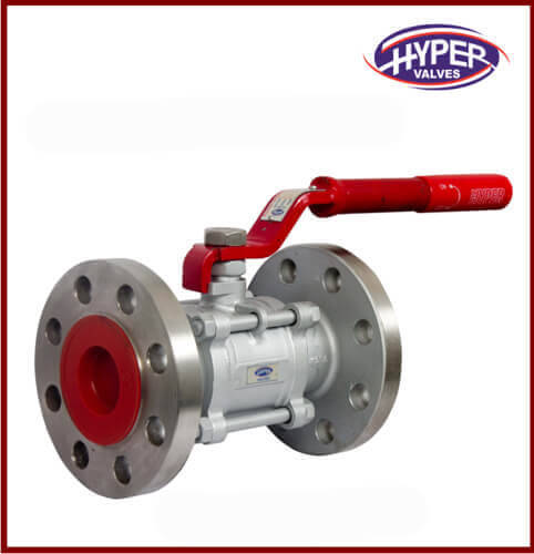
pneumatic valve in Kenya
Explore a wide range of high-quality valve positioners at Najem Alshahab, designed for precise control in industrial applications. Our valve positioners, including electric, pneumatic, and electro-pneumatic models, ensure accurate valve movement, enhancing operational efficiency. With features like easy adjustment, auto-tuning, and durability, they cater to diverse needs such as rotary and linear motion systems. Ideal for industries like water treatment, oil and gas, and manufacturing. Buy a Wide range of Pneumatic valves. We also supply Pneumatic valve and Actuator Valve products in other regions like Ghana, Kenya, Saudi Arabia, Riyadh and South Africa
0 notes
Text
Electro Pneumatic Positioner Market Size, Share and Price Analysis.
The electro-pneumatic positioner market refers to the industry that deals with the manufacturing, distribution, and sale of electro-pneumatic positioners.
Electro-pneumatic positioners are devices used in industrial processes to accurately control the position of valves and actuators. These positioners receive an electrical signal from a controller or a control system and convert it into a pneumatic signal, which is then used to position the valve or actuator. They play a crucial role in various industries, including oil and gas, chemical, power generation, water and wastewater treatment, and manufacturing.
The market for electro-pneumatic positioners has been witnessing growth due to several factors. The increasing demand for process automation in industries, the need for accurate control and positioning of valves, and the growing adoption of Industrial Internet of Things (IIoT) and digitalization are some of the key drivers for this market.
Enquiry now:- https://www.alliedmarketresearch.com/request-toc-and-sample/4452
The electro-pneumatic positioner market is highly competitive and consists of several manufacturers and suppliers. Companies in this market offer a wide range of products with different features and specifications to cater to the diverse requirements of industries. Some of the prominent players in the market include ABB Ltd., Emerson Electric Co., Siemens AG, Schneider Electric SE, and Yokogawa Electric Corporation.
The market is also influenced by technological advancements. Manufacturers are focusing on developing advanced electro-pneumatic positioners with improved accuracy, reliability, and communication capabilities. Integration of smart features such as diagnostics, predictive maintenance, and remote monitoring is becoming increasingly common.
Enquiry for price :- https://www.alliedmarketresearch.com/electro-pneumatic-positioner-market/purchase-options
Geographically, the market for electro-pneumatic positioners is spread across various regions, including North America, Europe, Asia Pacific, Latin America, and the Middle East and Africa. The Asia Pacific region is expected to witness significant growth in the market due to the rapid industrialization and infrastructure development in countries like China and India.

The global electro pneumatic positioner market is segmented based on type, end-user industry, and geography. By type, the market is divided into linear positioner and rotary positioner. By end-user industry, the market is divided into oil & gas, power generation, chemical, metal & mining, and others. Based on region, it is analyzed across North America, Europe, Asia-Pacific, and LAMEA.
Contact for Customization :- https://www.alliedmarketresearch.com/request-for-customization/4452
At present, the global electro pneumatic positioner market in dominated some key players namely: Actuant Corporation, Danaher Corporation, Emerson Electric Co., Hilti Corporation, Hitachi Koki Ltd., Makita Corporation, Robert Bosch GmbH, SKF, Stanley Black & Decker, Inc, and Techtronic Industries.
In summary, the electro-pneumatic positioner market is a dynamic and growing industry driven by the need for precise valve and actuator control in various industrial processes. The market is competitive, with a focus on technological advancements and the integration of smart features.
About Us:
Allied Market Research (AMR) is a full-service market research and business-consulting wing of Allied Analytics LLP based in Portland, Oregon. Allied Market Research provides global enterprises as well as medium and small businesses with unmatched quality of “Market Research Reports” and “Business Intelligence Solutions.” AMR has a targeted view to provide business insights and consulting to assist its clients to make strategic business decisions and achieve sustainable growth in their respective market domain.
Contact Us:
David Correa
5933 NE Win Sivers Drive
#205, Portland, OR 97220
United States
USA/Canada (Toll Free): +1–800–792–5285, +1–503–894–6022
UK: +44–845–528–1300
Hong Kong: +852–301–84916
India (Pune): +91–20–66346060
Fax: +1(855)550–5975
[email protected]
Web: https://www.alliedmarketresearch.com/reports-store/construction-and-manufacturing
0 notes
Text
Control Valve Manufacturer in USA

SVR Global is the leading and the top rated Control Valve manufacturer in USA. Control valve is operated electrically and it’s function is to control the flow of fluids through a pipeline as its name suggests. It can sustain smallest to largest capacity of fluid flow in numerous ways. This type of valve alter the spot of the plug or disc to control the flow of medium. It is controlled by an actuator. A control valve receives signal from a controller to change the flow by opening or closing the valve. The control valve manipulates the flow of medium in the form of gas, steam, water, or another suspended medium whenever there is load disturbance. Control Valve manufacturer in USA provides leak-proof, cost-effective valve delivered at your doorstep.
Control valve are used to maintain the process parameters to the optimal points as and when required. The controller set points of this valve are flow rate, pressure, and temperature. They also can sustain fluid static pressure and support seat surface and valve closure elements.
PARTS
Valve body: The valve body is the main housing that contains the valve mechanism and connects to the process piping.
Valve trim: The valve trim includes the internal components of the valve, such as the valve plug, seat, and stem. The valve trim is designed to control the flow rate of the fluid or gas passing through the valve.
Actuator: The actuator is the device that provides the force necessary to move the valve plug and adjust the flow rate. There are several types of actuators, including pneumatic, electric, and hydraulic.
Positioner: The positioner is a device that is used to accurately position the valve plug based on the control signal received from the controller. It is typically used in conjunction with an actuator to ensure accurate control of the valve.
Controller: The controller is the device that receives input from sensors and other sources to determine the desired flow rate, and sends a control signal to the valve actuator to adjust the valve position.
TYPES
Globe control valves: Globe valves are the most common type of control valve. They have a linear motion valve plug that is moved up and down to regulate flow. Globe valves are used in a variety of applications and can be designed for a wide range of temperatures and pressures.
Butterfly control valves: Butterfly valves are another common type of control valve. They have a disk-shaped valve plug that rotates to regulate flow. Butterfly valves are used in applications where low pressure drop and quick shutoff are required.
Ball control valves: Ball valves have a spherical valve plug that rotates to regulate flow. They are used in applications where high flow rates and tight shutoff are required.
Diaphragm control valves: Diaphragm valves use a flexible diaphragm to regulate flow. They are often used in applications where the fluid being handled is viscous or contains solids.
Single seat control valve: A single seat control valve has a single valve plug and seat. It is a common type of control valve used in industrial applications to regulate fluid flow.
Pinch control valves: Pinch valves use a flexible tube that is pinched to regulate flow. They are often used in applications where the fluid being handled is abrasive or corrosive.
Needle control valves: Needle valves have a long, tapered needle-shaped valve plug that is moved up and down to regulate flow. They are used in applications where precise flow control is required.
Three-way control valves: Three-way valves have three ports and are used to divert flow between two different directions or to mix two flows together.
INDUSTRIES
Oil & Gas Industry
Pipeline Industry
Marine Industry
Power Industry
Nuclear Industry
Mining Industry
Chemical Industry
Petrochemical Industry
APPLICATIONS
Chemical Processing: Control valves are widely used in chemical processing plants to regulate the flow of fluids and gases during chemical reactions.
Oil and Gas Production: Control valves are used extensively in the oil and gas industry to regulate the flow of fluids, gases, and other process variables during the production and processing of oil and gas.
Power Generation: Control valves are used in power generation plants to regulate the flow of steam and other fluids used in the generation of electricity.
Water Treatment: Control valves are used in water treatment plants to regulate the flow of chemicals and other substances used in the treatment process.
HVAC: Control valves are used in HVAC systems to regulate the flow of air or water, depending on the specific application.
ADVANTAGES
Precise control: Control valves provide precise control over the flow of fluids, gases, or other process variables, ensuring that the process is operating at optimal levels.
Energy efficiency: Control valves can be used to regulate the flow of fluids and gases to minimize energy consumption, reducing operating costs and improving efficiency.
Safety: Control valves can be used to regulate the flow of hazardous fluids or gases, ensuring that they are handled safely and minimizing the risk of accidents.
Reduced maintenance: Control valves can be designed to operate reliably for extended periods with minimal maintenance, reducing downtime and maintenance costs.
Flexibility: Control valves can be customized to meet the specific needs of a process, making them suitable for a wide range of applications.
Description:
Body Materials: Ductile Iron, Cast iron (WCB, WCC, WC6) LCC, LCB, Stainless Steel (SS316, SS304), Super Duplex (F51, F53, F55)
Class: 150 to 2500, PN10 to PN450
Operations: Electro Pneumatic and Pneumatic
Size: DN15 to DN600
Ends: Flanged, butt weld, socket weld, threaded
Visit our site for more information- https://svrglobal.net/products/control-valve/
0 notes
Text
PLC Controlled Hydraulic & Pneumatic System Trainer
Specification: a rodless cylinder (Ø 25 mm and stroke of 300 mm) a magnetic linear position sensor an electrically driven 5/3-way proportional pneumatic valve a filter unit with a 3-2-way loop valve, a dehumidifier with automatic drain, pressure reducer (0 to 8 bars) and a pressure gauge a flat supporting base and a sloping base of painted steel for cylinder- sensor set and proportional valve a spiral hose of plastic with airtight quick connect fittings, for air supply cables with plugs of 2 mm 1 analog input 0-10 V 1 analog output 0-10 V Power supply: 24 Vdc – 2A – 100 VA an electro-pneumatic flow control valve with proportional positioner an electronic flow-meter a filter unit with a 3-2-way loop valve, dehumidifier with automatic drain, 2 pressure reducers (0 to 8 bars) and 2 pressure gauges a flat supporting base and a sloping base of painted steel for the valve unit for the proportional flow control and the flow-meter a spir al hose of plastic with airtight quick connect fittings, for air supply cables with plugs of 2 mm a bidirectional pneumatic motor (6000 RPM max.) a tachogenerator (0-10 V) an electrically driven 5/3-way proportional pneumatic valve a filter unit with 3-2-way loop valve , a dehumidifier with automatic drain, pressure reducer (0 to 8 bars) and a pressure gauge a flat supporting base and a sloping base of painted steel for cylinder sensor set and proportional valve a spir al hose of plastic with airtight quick connect fittings, for air supply cables with plugs of 2 mm Accessories: Connecting Wire: 1 set User Manual: 1 N
Fabotronix’s is an Electrical and Electronics based Research and Development Company. There are several services that we offer. The services being Printed Circuit Board Design, Fabrication and Assembly, Industrial Training, Educational Industrial Trainer Development, Custom Electronics Design and Industrial Solutions. In the Industrial Solutions Sector we provide mostly microcontroller and PLC based solutions. We also design power charts for the industry.
0 notes
Text
The role of laser positioning
The laser locator is a special high-precision reference measuring instrument designed for the installation, maintenance and inspection of large-scale equipment. The light emitted by the laser locator is clear, bright, uniform in lines, high in collimation, intuitive and practical, stable, and easy to operate. The light target of the laser locator can be attached to the object to be measured, so that the user can complete the needs of detection, processing, installation, etc. It can be installed on the vertical or horizontal plane of the mechanical equipment, and the laser line can be arbitrarily fine-tuned in the three-dimensional space.
The laser positioner is made of a semiconductor laser and a linear optical lens system. It is used in industrial marking positioning lasers. It can be used as a standard component and widely used in various industrial processing machinery. It can play marking and positioning functions and increase the use of equipment. Convenience improves the working efficiency of the equipment and reduces material waste.
The marking of the laser locator is accurate, intuitive and practical, and can improve work efficiency. It is mostly used in bridge stone cutting machines. The laser locator measures the light spot at a long distance with a circular grid structure, and the image is clear, so that there is no need to adjust the focus during the whole measurement process, and the whole process has no focusing operation difference, thus ensuring that the laser beam provided by the host is a high-definition. Easy to distinguish laser beam.
The laser positioner is mainly used for knife setting of various sheet cutting and forming machines, tire building machines, woodworking machinery, stone bridge cutting machines, steel scribing and positioning, sheet metal shearing and pressing machinery, stone machinery, woodworking machinery, metal sawing machines, and packaging machinery. Put the line.
Laser locator is widely used in the fields of mechanical plate gold marking, electric saw marking and positioning, cutting machine material cutting marking and positioning, screen printing positioning, cross line template positioning, textile printing and dyeing garment positioning, tire positioning and other fields.
Changshu Desheng Optical Electronics Co., Ltd. was established in 2010, specializing in the R&D, production and sales of semiconductor laser modules. It is a qualified manufacturer of laser systems and laser projectors in various industries. Desheng focuses on the planning, development and manufacturing of high-stability and high-quality laser systems. Desheng has a group of professionals who have been engaged in design, research and development, and production management for more than 10 years. Desheng can provide domestic and foreign markets with high-quality, excellent performance and cost-effective laser modules in a timely manner. We conform to the trend of artificial intelligence automation. Desheng warmly welcomes you to share your ideas with us. We are 635nm 180mw Laser Module Positioning manufacturer, if you need it, please contact us.
0 notes
Text
Maximizing Performance with Linear Electric Positioners
Linear electric positioners are a critical component in many industrial processes that require precise linear motion control. In this guide, we explore how these devices work, their key features, and how they can be optimized for maximum performance in a variety of applications.
0 notes
Text
All About Pneumatic Actuators
Pneumatic actuators use air power to produce rotary and linear motion. In the broadest sense, an air cylinder is a pneumatic actuator. For the purpose of this article, pneumatic actuators that are intended to produce rotary motion for operating valves, for automating manufacturing, for clamping work, etc. are the primary focus. Their use in linear applications such as valve operating and positioning is also discussed. Air cylinders, in general, are not covered. For information on other types of actuators, please see our related Actuators Buyers Guide.
Pneumatic rotary actuators
Pneumatic rotary actuators rely on a variety of mechanisms to produce rotary motion. Two common styles use pistons or diaphragms. In one style, the piston moves a rack past a gear pinion, rotating the pinion to produce a limited range of rotation at the output shaft. Another style uses a scotch yoke, a well-known kinematic link, to produce up to 90° of rotation of the output shaft. A third method uses no pistons or diaphragms but instead employs one or two vanes that are pressurized to produce rotary motion directly within a round housing.
Rack-and-pinion styles use at least one, and sometimes two or four, cylinders to drive the rack(s) past the pinion. The pinion rotates in response, driving the output shaft. A rack-and-pinion actuator will continue to revolve the pinion until it reaches the end of the stroke, although modulation is possible. In many instances, the pistons in the cylinders will work against large coil springs which provide the valve with the capacity to return to a safe position during a power interruption. Diaphragms are sometimes used in place of pistons but the operating principle remains the same. The number of revolutions a rack-and-pinion actuator can make is limited only by the length of the rack.
Scotch-yoke actuators are usually limited to 90° of rotation and see applications in quarter-turn valves. Pneumatic vane actuators can produce rotations in excess of 360°.
Pneumatic actuators work with on/off valves such as ball valves. They can be adapted to work with control valves as well. Control valves necessarily need to be positioned at intermediate locations in order to regulate fluid flow. Modulating pneumatic actuators are available for this task. Typically, a 3-15 psi industry-standard air pressure signal is sent to a modulating positioner at the valve, which adjusts (in the case of a quarter-turn valve) the valve stem anywhere between 0 and 90° depending on downstream flow measurements. Electro-pneumatic positioners do the same thing using electrical signals.
Motion-control applications using pneumatic rotary actuators generally fall into the rack-and-pinion or vane styles. Often, double-acting rack-and-pinion arrangements are used. Multi-position actuators, with three, four, or five stops, are often used for sequential assembly operations. Rotary actuators may also be used for indexing, stepping, and pick-and-place motions.
Pneumatic linear actuators
Pneumatic linear actuators are used on rising-stem valves to directly operate the gate, globe, etc. Two types are normally used, the diaphragm and the piston. Diaphragm styles are popular as their wide surface areas can produce tremendous force with moderate air pressure. The diaphragm is a rubber membrane whose rim is sealed to the outer casing of the actuator. Air pressure displaces the diaphragm up or down against spring pressure depending on whether the actuator is designed to fail open or fail closed. Stroke lengths are generally shorter than piston valves where strokes are dependent only on the length of the cylinder, not the amount of stretch the diaphragm can tolerate. Piston style actuators can be sized to produce an appropriate actuating force based on the pressure of available air and can be manufactured in double-acting and spring-return styles. Some linear actuators use the familiar air springs in place of diaphragms.
As globe valves are common for control applications, modulating linear actuators are available. Pneumatic modulating valves are particularly effective because their speed is adjustable by throttling the airflow. Thus, a pneumatic actuator can speed quickly toward a setpoint but slow as it reaches it, eliminating overshoot. Unlike electric actuators, pneumatic actuators can run continuously.
Combination rotary/linear actuators
The ability to provide both linear travel and limited rotation is handy in certain applications such as work holding. Clamps can be raised and swung clear of a workpiece to allow its removal and then pressurized and reengaged once a new workpiece is positioned.
Applications
Air-powered actuators are a proven method of obtaining rotary and linear motion. For valve actuation, both on/off and control, air provides a reliable, safe, economical method. Discounting the cost of furnishing compressed air itself, air actuators are usually more cost-effective than electric actuators up to a certain diameter valve. As valves become larger, the economics begin tilting more in favor of electric actuators.
Electrical valve actuators are being employed with greater frequency. Still, pneumatic actuators have their proponents due to their simplicity, ruggedness, and ease with which they are made fail-safe. They can move faster than electric actuators and are not subject to duty cycles. Efforts to make traditional pneumatic and hydraulic actuators more compatible with distributed control systems are ongoing.
Rotary actuators are used in many motion-control systems to operate, for instance, pick-and-place handlers or clamps. Linear air cylinders have long been a staple of automation and continue to be so despite the influx of sophisticated stepper- and servo-motor driven electrical actuators. While their primary application is in point-to-point moves, cylinders equipped with feedback are enabling servo-pneumatic actuators to handle positioning applications that are too fine for ordinary cylinders yet too coarse for electrical actuators. Such devices can provide high forces in small packages and can operate continuously without heat buildup. Part of their development has been in figuring out control algorithms that can account for the compressibility of air, which has always made air cylinders better for point-to-point motions.
For more information please visit: www.uflow-pneumatic.com
0 notes
Text
Know Your Pneumatics: Rotary Actuator Basics
Pneumatic actuators are commonly used to convert compressed air pressure (in the form of a cylinder stroke) into an oscillating rotary motion. Like other pneumatic components, they are durable, offer simplicity and high force for their size, and can operate in hazardous environments.
There are two main types of pneumatic rotary actuators: rack and pinion, and vane – both are available in either single or double actuation:
Rack and pinion rotary actuators use a cylinder piston attached to a rack gear. When actuated, the piston and rack move in a linear fashion rotating the pinion gear and output shaft. A double rack unit utilizes two racks on opposite sides of the pinion gear, in effect, doubling the output torque of the unit.
Vane actuators have a cylindrical chamber in which a vane is mounted on a central shaft. Air pressure applied on one side of the vane forces it to rotate until it reaches the end of the stroke. Alternatively, air pressure from the opposite side of the vane drives the shaft in the opposite direction until it reaches the end of stroke. In a single vane style, the rotary motion is typically limited to 280 degrees. In a double vane style, the motion is typically 90 or 100 degrees, offering less rotational range with double the force of the single vane construction. Our Series is an example of a vane actuator available in 9 sizes in single or double vane versions.
Rotary actuators can often be overlooked in the specification process as common pneumatic cylinders are specified with a pivot arm to achieve the necessary rotary motion. However, rotary actuators have the potential to greatly simplify applications because they are self-contained components capable of supporting loads due to the internal bearing sets.
Additionally, there is no need to design and construct external pillow block bearings. Unlike piston rods exposed to airborne contaminants, rotary actuators can reduce maintenance headaches in dirty environments.
A butterfly valve is a quarter-turn rotational motion device that utilizes a rotary disc to allow, obstruct, or control the flow of fluids in a piping system. It features a rotating disc that is situated on the passageway of the flowing media. The disc is rotated and controlled by an external actuating mechanism through the stem attached to it. When the disc is coplanar to the flow cross-sectional area, the flow is fully obstructed. Otherwise, the fluid is fully or partially allowed to pass through the butterfly valve. It takes a 900 turn to fully open a butterfly valve from a closed position, which means the disc should lie perpendicular to the flow cross-sectional area.
Butterfly valves are quarter-turn valves like ball valves and plug valves. They have a fairly simple construction and operation mechanism, and they have a compact size designed to fit two pipe flanges.
They can be operated manually or by an automatic actuating mechanism that is integrated into the process control system of the pipeline. They are ideal for on-and-off applications, but their applications to flow throttling are limited.
There are several types and designs of butterfly valves available, rated in varying temperatures, pressures, and flow rates to suit the needs of pipeline systems handling liquids and gases.
A limit switch box is an electromechanical device operated by a physical force applied to it by an object. Limit switches are used to detect the presence or absence of an object. These switches were originally used to define the limit of travel of an object, and as a result, they were named Limit Switch.
A solenoid valve is an electrically controlled valve. The valve features a solenoid, which is an electric coil with a movable ferromagnetic core (plunger) in its center. In the rest position, the plunger closes off a small orifice. An electric current through the coil creates a magnetic field. The magnetic field exerts an upwards force on the plunger opening the orifice. This is the basic principle that is used to open and close solenoid valves.
There are several features of a filter regulator, all as important as the last. The point of an airline filter, regulator, lubricator is to ensure that every component or process is receiving a clean and lubricated supply of compressed air. But, this must also be done at the correct pressure to achieve peak performance. It is stated that every 2-psi increase in operating pressure adds an additional 1% to compression energy cost. Therefore, unregulated or incorrect pressure settings can result in increased compressed air demand and consequently high energy consumption. This excess of pressure can also create equipment wear, causing a rise in maintenance costs and a limited application lifespan. Air filter regulators maximize longevity and reliability, making them an essential component of many applications.
There are a few different types of valve positioners available. Depending on the type of positioner, it either uses air or electricity to move the actuator. Let’s discuss some of the popular options. Pneumatic positioners receive pneumatic signals (usually 3-15 psig). The positioner then supplies the valve actuator with the correct air pressure to move the valve to the required position. Pneumatic positioners are intrinsically safe and can provide a large amount of force to close a valve. Electric valve positioners receive electric (usually 4-20 mA) signals. They perform the same function as pneumatic positioners do, but use electricity instead of air pressure as an input signal. There are three electric actuation types: single-phase and three-phase alternating current (AC), and direct current (DC) voltage. Electric-pneumatic valve positionerss convert current control signals to equivalent pneumatic signals. It uses a mix of both electricity and air, as implied by the name.
0 notes
Text
What is the goal of a control valve?
A control valve manages fluid flow by changing its size or direction in response to controller input. It aids in the direct control of flow rate and the regulation of other critical process variables, including temperature, liquid level/flow, and pressure. In automatic control terminology, it is also known as the "final control element."
In other words, a Safety Valve is used to regulate the flow, pressure, liquid level, and temperature of a system by entirely or partially opening or closing it in response to controller signals. The positioners control the closing and opening of the electric, hydraulic, and pneumatic actuators, which govern the opening and shutting of the control valve.
How does it work?
To offer constant quality goods, the process plant has several control loops. These control loops have a predetermined pressure, temperature, flow, and level to maintain the desired working range. Internal disturbances occur in each of these control loops, which are monitored by sensors and transmitters. The controllers subsequently analyze the acquired data, who determine what should be done to correct the load disruptions. A controlling element is implemented after the data has been examined, measured, compared, and calculated. The control valve enters the scene at this point and works to lessen the disturbances.
As a result, the control valve's working concept relies on manipulating flowing fluids like water, gas, steam, or chemical compounds to guarantee that load disturbance is minimized, and the process variable is regulated to the closest value of the desired set point.
Gate valves are used to open and close doors.
The Automatic Control Valve is made up of a flat barrier that may change the flow area. It has an on-off application and is well suited to regulate high temperature and pressure for various liquid flows. The valves that regulate the automated emergency cut-off and the hand-operated valves have this design or body.
THE BENEFITS OF A GATE VALVE
· It features an excellent Closing feature.
· In a circuit, it can be used in either direction.
· It creates laminar flow, resulting in minimal pressure loss.
GLOBE VALVE

The phrase "globe valve" refers to the outer shape of the valve, which is utilized for throttling. The globe valves have a stem that moves up and down in a linear motion to modify the position of the plug. It has a short stem journey, a lot of seating capacity, a lot of pressure drop, and flow controllability.
THE BENEFITS OF A GLOBE VALVE
· Has an excellent full-closing feature.
· Because the strokes are more minor, the valve opens and closes faster than a gate valve.
· Has a practical throttling feature.
· With little change in shaft disconnection, it can be used as a stop check valve.
PLUG VALVES
Plug valves are made up of a plug, a body, and a cover and are used for on-off services in refineries, chemical plants, and petrochemical plants. Typically tiny in size, they require less headroom and come in a variety of materials. They provide a tight seal, rapid opening, and minimal pressure drop.
· It is made up of only a few elements and has a straightforward design.
· Easily opens and closes.
· It is simple to maintain and repair at the location of operation.
· They offer a low flow resistance and a leak-proof feature that is trustworthy.
BALL VALVES
The pressure and flow of corrosive fluids, regular liquids, gases, and slurries are controlled by a ball valve. It also keeps high temperatures and stress under control.
BALL VALVES HAVE MANY BENEFITS
· Provides a leak-free service.
· Service that is quick to open and close.
· When compared to gate valves, it has a relatively modest size.
· In comparison to gate valves, it is lightweight.
· Has the ability to reduce the number of valves necessary by using a multi-way design.
· Under high temperature and pressure conditions, it provides dependable and safe service.
· When compared to gate and globe valves, it requires less force to operate.
DIAPHRAGM VALVES
For corrosive fluids at low temperatures and pressures, a diaphragm valve is utilized by deforming one surface with force from the valve stem.
ADVANTAGES OF DIAPHRAGM VALVES
· The diaphragm isolates the working parts from the process fluids completely.
· Construction is simple, making it easier to operate and maintain.
· It has hassle-free functioning due to its basic design and convenience of use.
· It can be utilized for a variety of purposes, including opening, throttling, and closing.
· It provides solid chemical resistance because it is based on the body's internal sheathing.
· There is no shaft leakage since the fluid is kept separate from the bonnet group.
· Heavy chemical, chemical, and radioactive fluids are all compatible.
· It can protect the system from microbiological contamination because the fluid is kept apart from the bonnet group, and it can be utilized in the food, pharmaceutical, and beer industries.
0 notes
Text
Global piezoelectric actuator market
Global piezoelectric actuator market
size was US$ XX Bn in 2019 and is expected to reach US$ XX Bn by 2027, at a CAGR of ~4% during the forecast period.
The report study has analyzed the revenue impact of COVID -19 pandemic on the sales revenue of market leaders, market followers, and market disrupters in the report, and the same is reflected in our analysis.
Market Definition
Piezoelectric actuators are devices that are used to convert electrical signals into linear motion or mechanical displacement with unlimited resolution, high force, and speed. They are widely used in the high precision positioning mechanism as it provides benefits such as ease of use, stable displacement, and large generated force.
Market Dynamics
A surge in the adoption of piezoelectric actuators in various advanced high-tech sectors such as semiconductor inspection & test, bio-nanotechnology, aerospace and astronomy technology and in super-resolution microscopy field is major driving factor behind the growth of the market. A growing adoption of piezoelectric actuators in precision motion control applications, rising significance in high-frequency switches and industrial automation, increasing demand of piezoelectric actuators in aerospace applications and growing technological advancements in piezoelectric effect are expected to improve growth of the market during the forecast period.However, high initial cost required for the integration of piezoelectric actuators into the industrial machines is the major restraining factor that could hamper the growth of the market.
Global Piezoelectric Actuator Market: Segmentation Analysis
By industry, medical segment dominated the market in 2019 and is projected to witness fast growth at a CAGR of XX% during the forecast period. A surge in the adoption of piezoelectric actuators in variety of medical devices such as in surgical devices, laser beam steering devices, micro dose dispensers, micro-liter and nano-liter pumps, ultrasonic emitters and in 3D scanners is accredited to the growth of the market. In addition, rising significance of piezoelectric actuators in applications such as MRI-compatible robotics, drug delivery and material handling applications are expected to expand growth of the market in medical industry.
Alternatively, aerospace and defence segment is projected to witness fast growth at a CAGR of XX% during the forecast period. A growing adoption of piezoelectric devices such as actuators, sensor and motors in aerospace and defence applications is attributed to the growth of the market. An increasing use of piezoelectric actuators in various parts of aircraft to damp unwanted vibrations, rising significance of this actuators is in wind turbines, planes, motors, laboratory tables and machine tools and rising production of commercial and military aircrafts are likely to impel growth of the market during the forecast period.
Global Piezoelectric Actuator Market: Regional Analysis
Region wise, Asia pacific held the largest market share in 2019 and is expected to maintain its dominance at CAGR of XX% during the forecast period. The developing economies such as China, Japan, South Korea, and India are the major key contributors behind the growth of the market. The growth is attributed to the high adoption of piezoelectric actuators in industries such as automotive, aerospace and defense and medical industry across the globe.
Growing technological advancements in micro electromechanical (MEMS), materials, manufacturing and biotechnology field, rapid growth in industrial automation technology and rising adoption of piezoelectric actuators in semiconductor processing equipments are driving the growth of the market in APAC region.
The objective of the report is to present a comprehensive analysis of the Global Piezoelectric Actuator Market including all the stakeholders of the industry. The past and current status of the industry with forecasted market size and trends are presented in the report with the analysis of complicated data in simple language. The report covers all the aspects of the industry with a dedicated study of key players that includes market leaders, followers and new entrants. PORTER, SVOR, PESTEL analysis with the potential impact of micro-economic factors of the market have been presented in the report. External as well as internal factors that are supposed to affect the business positively or negatively have been analyzed, which will give a clear futuristic view of the industry to the decision-makers. The report also helps in understanding Global Piezoelectric Actuator Market dynamics, structure by analyzing the market segments and projects the Global Piezoelectric Actuator Market. Clear representation of competitive analysis of key players by Application, price, financial position, Product portfolio, growth strategies, and regional presence in the Global Piezoelectric Actuator Market make the report investor’s guide.
For More Information Visit :
https://www.maximizemarketresearch.com/market-report/global-piezoelectric-actuator-market/78990/
Scope of Global Piezoelectric Actuator Market
Global Piezoelectric Actuator Market, By Type
• Multilayer Actuators• Multilayer Chip Actuators• Bulk Stacked Actuators• Shear Actuators• Amplified Actuators• BendersGlobal Piezoelectric Actuator Market, By Application
• Valves• Printed Heads• Positioners• Optical Instruments• Scientific Instruments• OthersGlobal Piezoelectric Actuator Market, By Industry
• Automotive• Medical• Consumer Electronics• Aerospace & Defence• Manufacturing & Processing• OthersGlobal Piezoelectric Actuator Market, By Region
• North America US Canada• Europe UK France Germany Italy Spain Norway Russia• Asia Pacific China India Japan South Korea Australia Malaysia Indonesia• South America Brazil Mexico Argentina• Middle East and AfricaGlobal Piezoelectric Actuator Market, Key Players
• APC International Ltd.• Cedrat Technologies• CeramTec GmbH• CTS Corporation• TDK Corporation• Johnson Matthey• Kinetic Ceramics• Murata Manufacturing Co. Ltd.• Tokin Corporation• NGK Insulators• PCB Motor Ltd.• Physik Instrumente (PI) GmbH & Co. KG.• Piezomechanik GmbH• Steminc (STEINER & MARTINS, INC.)• Thorlabs Inc.• Ningbo Best Group Co., Ltd.• Hanse-john Electronics Co., Ltd• Piezo Hannas (Wuhan) Tech Co Ltd.• Sinocera Piezotronics, INC• XX
• XX
This Report Is Submitted By : Maximize Market Research Company
Customization of the report:
Maximize Market Research provides free personalized of reports as per your demand. This report can be personalized to meet your requirements. Get in touch with us and our sales team will guarantee provide you to get a report that suits your necessities.
About Maximize Market Research:
Maximize Market Research provides B2B and B2C research on 20,000 high growth emerging opportunities & technologies as well as threats to the companies across the Healthcare, Pharmaceuticals, Electronics & Communications, Internet of Things, Food and Beverages, Aerospace and Defense and other manufacturing sectors.
Contact info:
Name: Lumawant Godage
Organization Address: MAXIMIZE MARKET RESEARCH PVT. LTD.
Email: [email protected]
Address : Pune, Maharashtra 411051, India.
Contact: +919607195908
0 notes
Text
Covid-19 Outbreak: Electropneumatic Positioner Market 2020 Top Manufactures, Growth Opportunities And Investment Feasibility 2027
Electro-Pneumatic Positioner: Introduction
Electro-pneumatic positioner is an equipment that controls the motion involved in the valves and actuators that improves the productivity of the equipment.
Electro-pneumatic positioners are made of vibration-resistant and corrosion-resistant aluminum die-cast. It provides a simple structure for feedback connection, sensitive response, and easy maintenance.
The two types of electro-pneumatic positioners available in the market includes linear acting, and rotary acting electro-pneumatic positioners. These are used in chemical, electric power generation, metals & mining, textile, marine, oil & gas, refining, and water & wastewater end-use industries.
Manufacturers are moving from conventional pneumatic positioners to fully digitalized electro-pneumatic positioners.
Rise in Demand in the Oil & Gas Industry
By end-use industry, the oil & gas industry is expected the fastest growing segment of the electro-pneumatic positioner market during the forecast period.
Consumption of fuel & gas is increasing globally and companies operating in the oil & gas industry are always looking to cut their operating costs and enhance the overall efficiency of oil & gas plants. This encourages the installation of electro-pneumatic positioners in control valve assemblies that supports efficient plant operations of the oil & gas industry.
Moreover, electro-pneumatic positioners are critical components which determine plant efficiency. This is expected to drive the demand for electro-pneumatic positioners in new installations.
Profit margins get reduced and presence of unorganized manufacturers hinders the entry of national and international suppliers. These are major restraints of the global electro-pneumatic positioner market.
For Right Perspective & Competitive Insights on Electro-Pneumatic Positioner Market, Request for a Sample
Asia Pacific to Lead the Electro-Pneumatic Positioner Market
In terms of region, the global electro-pneumatic positioner market can be divided into North America, Europe, Asia Pacific, Middle East & Africa, and South America.
Asia Pacific is expected to witness the highest growth in the electro-pneumatic positioner market throughout the forecast period due to rising urban population in APAC, positive prospects for the oil & gas industry in the region, and growth in pipelines in Asian countries such as China, Japan, India, Indonesia, and Australia.
Moreover, the high demand for new and improved wastewater treatment systems, and growing recognition of water as a resource for various purposes in manufacturing and agriculture also propels the growth of the electro-pneumatic positioner market in the region.
North America is expected to hold the second largest share of the electro-pneumatic positioner market during the forecast period due to increased spending on electro-pneumatic positioners in the next few years, and the high growth of the oil and gas industry that increases the use of electro-pneumatic positioners.
The electro-pneumatic positioner market in Europe is expected to expand at a substantial rate during the forecast period. On the other hand, the market in Middle East & Africa and South America is estimated to expand at a moderate pace during the forecast period.
Key Players Operating in the Global Electro-Pneumatic Positioner Market
The global electro-pneumatic positioner market was highly fragmented in 2019. Major players operating in the global market are focusing on technological advancements and expansions to meet the rising demand for electro-pneumatic positioners. Moreover, manufacturers are undertaking mergers and acquisitions for the development of innovative products.
Key players operating in the global electro-pneumatic positioner market are:
Emerson Electric
Schneider Electric
ABB
Siemens AG
Baker Hughes
Flowserve
Actuant Corporation
Danaher Corporation
Hilti Corporation
Hitachi Koki Ltd.
Makita Corporation
Robert Bosch GmbH
Techtronic Industries
Are you a start-up willing to make it big in the business? Grab an exclusive PDF Brochure of this report
Global Electro-Pneumatic Positioner Market: Research ScopeGlobal Electro-Pneumatic Positioner Market, by Type
Linear
Single Acting
Double Acting
Rotary
Single Acting
Double Acting
Global Electro-Pneumatic Positioner Market, by End-use Industry
Chemical
Electric Power Generation
Metals & Mining
Textile
Marine
Oil & Gas
Refining
Water & Wastewater
This study by TMR is all-encompassing framework of the dynamics of the market. It mainly comprises critical assessment of consumers' or customers' journeys, current and emerging avenues, and strategic framework to enable CXOs take effective decisions.
Our key underpinning is the 4-Quadrant Framework EIRS that offers detailed visualization of four elements:
Customer Experience Maps
Insights and Tools based on data-driven research
Actionable Results to meet all the business priorities
Strategic Frameworks to boost the growth journey
The study strives to evaluate the current and future growth prospects, untapped avenues, factors shaping their revenue potential, and demand and consumption patterns in the global market by breaking it into region-wise assessment.
The following regional segments are covered comprehensively:
North America
Asia Pacific
Europe
Latin America
The Middle East and Africa
More Trending Reports by Transparency Market Research -
1. https://www.prnewswire.com/news-releases/increasing-demand-for-efficient-and-reliable-power-transmission-to-propel-growth-of-global-fault-circuit-indicator-market-tmr-projects-valuation-to-rise-up-to-us2-2-bn-by-2027--301006480.html
2. https://www.prnewswire.com/news-releases/global-racing-drone-market-to-reach-valuation-of-us786-mn-by-2027-increasing-popularity-of-commercial-racing-events-to-drive-growth-finds-tmr-301007400.html
About Us
Transparency Market Research is a next-generation market intelligence provider, offering fact-based solutions to business leaders, consultants, and strategy professionals.
Our reports are single-point solutions for businesses to grow, evolve, and mature. Our real-time data collection methods along with ability to track more than one million high growth niche products are aligned with your aims. The detailed and proprietary statistical models used by our analysts offer insights for making right decision in the shortest span of time. For organizations that require specific but comprehensive information, we offer customized solutions through adhoc reports. These requests are delivered with the perfect combination of right sense of fact-oriented problem solving methodologies and leveraging existing data repositories.
TMR believes that unison of solutions for clients-specific problems with right methodology of research is the key to help enterprises reach right decision.”
Contact
Transparency Market Research
State Tower,
90 State Street,
Suite 700,
Albany NY - 12207
United States
USA - Canada Toll Free: 866-552-3453
Email: [email protected]
Website: https://www.transparencymarketresearch.com
0 notes
Text
How Do Control Valves Work In The Instrumentation Industry?
Control valves are devices that, by opening and closing according to the controller, can control certain conditions such as pressure, temperature, flow, and liquid level; the control valve is often referred to as the final control function. The controller sends out the signal by comparing a fixed point to a process variable. The final control factor is instrumentation valves for in-process control industries. To compensate for the load disruption, the control valve will control the liquid-like gas, steam, and water flow.
Electrical, hydraulic, or pneumatic actuators are automatically used to shut and open a control valve. Positioners monitor the actuators' closure, which is performed by the positioners according to electrical or pneumatic signals. Instrumentation valves consist of parts of the inner trim, valve body, actuators that can provide the required amount of power to operate the valve, and other accessories such as positioners, transducers; pressure regulators limit switches. In pipelines, control valves are used for establishing externally variable and customizable restrictions.
How to use control valves in instrumentation work?
Process plants consist of control loops of hundreds, or even thousands, all networked together to create a commodity to be sold. within a required operating range to ensure the end product's quality.
These loops obtain and create changes internally that have a negative effect on the process variable, and input from other system loops generates things that impact the process variable. Sensors and transmitters collect information about the process variable and its relation to some desired fixed point to decrease these load disturbances.
This information is then interpreted by a controller and defines what must be done to get the process variable back to where it should be after a load disturbance happens. When all weighing, measuring, and estimating are done, some final control function must implement the controller's strategy.
Conventional Double Seat Valve
Because a larger valve with a more considerable sacrifice is used to pass through larger amounts of the medium, it would also increase the force that the actuator needs to produce to close the instrument valves. The point can be reached where it becomes impossible to have adequate force to close a traditional control valve when very large capacity must be passed using large valves or very high differential pressures.
The primary solution to this problem in such a situation is the double seat valve to achieve a roughly balanced design.
It is a critical decision to pick the right control valves for your project loop. Cost-effectiveness, efficiency, and protection are on the line. Keep the flow of gases and liquids going smoothly? Industrial transport of liquids and gases, from energy to foodstuffs, is part of many things. You can need rotary or linear valves depending on the design of the objects transferred. The choice of instrumentation valve suppliers is as crucial as the choice of valves. Actuators also provide the necessary speedy response and automation for precise process control.
0 notes
Text
Know more about Welding Techniques and equipment which are used commonly by leading service providers
‘Hobart Brothers’ was a family unit until it was acquired by Illinois Tool Works (ITW) in 1996. ITW is a multinational corporation that manufactures a varied range of value-adding and short-lead-time industrial commoditiesand equipment and is also the father company of Miller Electric Manufacturing.
Hobart welding equipmentis one of the best suppliers of various welding equipment and there supply chain in Miami known as Miller welders Miami have the best team to take care of your onsite welding works.
Common types of welding and what they are used for
Generally, only four welding types are used commonly for the simple reason as they are the best by Miller welding supply Miami, and they are MIG, TIG, Stick, and Flux-Cored arc welding.There are usually more than 35 different types of welding whichare there, and they vary from simple methodologies like oxy-fuel to high-tech processes such as laser beam welding
· MIG Welding.
· Stick Welding.
· TIG Welding.
· Plasma Arc Welding.
· Electron Beam and Laser Welding.
· Gas Welding.
Hobart Welding Miami uses those welding machines and joining machines that encompass devices that are used for numerous joining processes.
These processes include:
· Arc welding (MIG, TIG, stick, submerged arc)
· Resistance welding
· Laser welding
· Electron beam welding
· Stud welding
· Orbital welding
· Wave soldering
· Hot-dip brazing
· Torch brazing
· Induction brazing
· Ultrasonic
· Friction welding
Complete set-up of a welding machine or joining machine system consists of complete welding, surfacing, or cutting machines, equipment, or system. Also, a power source, torch or gun, cables, feeders, positioners, robots, or other required components are included.
Generally, a power source for a welding machine or a joining machine provides a TIG gun, MIG gun, electrode holder, laser, electron beam gun, or other welding units with sufficient output power to melt material.
Welding monitors or controllers for welding machines are equipment that perceivesthe quality of weldingslike nugget size or weld integrity or output power supply variations.
Generic Arc or resistance-welding types are:
· Flux Cored Arc Welding (FCAW)
· Gas Metal Arc Welding (GMAW)
· Multi-process
· Orbital / Tube Arc Welding
· Plasma arc welding
· Flash welding
· Projection welding
· Resistance seam welding
· Spot welding
· Shielded Metal Arc Welding (SMAW)
· stud arc welding
· Submerged arc welding (SAW)
· Gas Tungsten Arc Welding (GTAW)
Frictional or other fusion welding types include:
· Electron beam welding
· friction welding
· Hot plate welding
· plastic welding
· Laser welding
· Oxy-fuel welding
· Thermite or exothermic welding
· ultrasonic or linear friction welding
You need to be aware of the duty cycle, or the percentage of time the welding unit can remain on in a ten-minute period before powering off to cool and prevent damage to components. Check the output power capability specifications, which include AC output, DC output, AC/DC selectable output, and high frequency. Also look at the output voltage range, which is the proposed range of voltage of the welding unit.
Generators which are engine driven, machine duty or corrosion resistance, multi-operator, and water-cooled are features that are common to the best welding and joining machines.
For more info : -
Lincoln electric Miami
0 notes
Link
Selection and Applications of Control Valves
July 3, 2017
P.Eng.
Meena Rezkallah
Definition of Control Valves
Unlike valves in a piping system that primarily serve to shut off, drain, fill, or divert, control valves are a part of an automated control system. They are considered the ‘‘final control element’’ in an automated and usually very sophisticated ‘‘control loop.’’ Aside from the control valve, the ‘‘loop’’ consists of a transmitter that measures the variable to be controlled (usually pressure, flow, level, or temperature) and a controller (nowadays a computer of sorts). Following an error in the variable to be controlled (such an error being sensed by the transmitter), the controller sends a signal change to the control valve which, in turn, responds by altering the flow rate through the valve sufficiently to restore the desired variable (such as pressure, for example).
Control valves have basically three interactive components: (1) a valve body sub assembly (either with a reciprocating or rotating stem), (2) an actuating device (usually a spring diaphragm type), (3) a valve positioner (an instrument that converts an electronic control signal from a controller, or computer, into an air signal to control the position of the control valve stem), and (4) an airset or regulator to supply air pressure to the positioner (see Figure A10.34).
How to Specify Control Valves
The first step in specifying a control valve is to define its function in the given application. In some, it will operate as an on-off valve that opens or closes following the commands of a programmable controller on, say, a batch process. In others, it will be used to remotely set a flow rate in a process—that is, it will be used as a manually controlled variable orifice in a pipe (an open-loop application). Finally, in more sophisticated applications, the control valve will serve as the final control element in a process control loop and respond to the sometimes infinitely small variations of a signal coming from a controller (typically a computer). The signal will be generated in response to a deviation in the desired temperature, pressure, or level of a process fluid as measured by a transmitter.
Application Classes
In the first type of application, any on-off valve with a pneumatic or electrical actuator (say, for example, a ball valve) may suffice. The requirements are to provide tight shutoff (perhaps with a Teflon® seat) to withstand the pressure, temperature, and corrosiveness of the fluid, and, finally, to have sufficient flow capacity. No valve positioner is required (see Figure A10.35).
Open-loop control requires a higher level of sophistication, such as a character- ized valve plug and good repeatability. The latter calls for a valve/actuator combina- tion with low dead band (low friction). A valve positioner, a device that is essentially a stem position controller with an accuracy between 0.5 and 1.0 percent of stem position, may be required. Controlling the stem position may not always assure that the valve plug or ball moves the required amount unless the stem or shaft is pinned or welded to the ball, vane, or plug (unless fluid pressure assures constant contact). See Figure A10.36.
The modulating control valve that is part of a control loop is the most sophisticated device. Typical features are plug or ball with either linear or equal percentage flow characteristic, low-friction packing and actuating devices, and, if required, low-noise or anticavitation features. These are in addition to the previously stated requirements.
Figure A10.37 shows an eccentric rotary plug valve with a low noise restrictor in the valve outlet port. Part of the pressure drop at moderate to high flow rates occurs across this slotted device. The smaller jets created by the slots produce about 10 to 15 dBA less noise than the valve itself.
Flow control is only possible if the control valve can reduce some of the fluid pressure. Such pressure reduction (also used for valve sizing) typically amounts to 5 to 10 percent of the maximum pump pressure. This makes a streamlined valve trim (highly desirable for on-off valves) actually less desirable for control purposes. It takes much higher velocities with a streamlined trim or valve (hence, more noise or cavitation) to achieve a certain pressure drop than with a nonstreamlined valve. Signals from controllers to control valves are 3 to 15 psi (0.2 to 1.0 bar) if pneumatic or 4 to 20 mA if electronic. Digital signals will be used in the future
once the question of fieldbus standardization has been resolved.
Control Valve Styles.
Let’s take a look at the characteristics of some of the most commonly used control valve types:
Globe valve. The globe valve (see Figure A10.34), which is the most widely used type of control valve, has a screwed-on, integrally attached, or cage-supported seat ring, and typically a lathe-turned, single-seated valve plug. Larger valves or high-pressure valves may have designs such that the valve plug is cage-guided and pressure-balanced to reduce actuator force requirements. Globe valves are cost effective in sizes NPS 2 (DN 50) and below and are available in sizes as small as NPS ¹⁄₄ (DN 6) for research applications. End connections are flanged or threaded. High-pressure or high-temperature valves can be welded to the piping. NPS 2 (DN 50) and smaller can be provided with socket-welding or threaded ends. NPS 2¹⁄₂ (DN 65) and larger are generally butt-welded or flanged.
Angle valves. Angle valves are a special variety of globe valves typically having an inlet port at a right angle to the valve stem and a discharge port in line with the valve orifice. Typical applications include flashing and erosive fluids.
Three-way valves. As the name implies, three-way valves are globe valves (or some rotary valves) that have three access ports and two plugs and orifices opposed to each other. Depending on the flow direction, three-way valves may serve as either mixing valves (where two different fluids enter the valve through two of the ports, and discharge as a mixture through the third), or diverting valves around heat exchangers (for example, where a fluid enters at one port and discharges through either the second or the third port).
Eccentric rotary plug valves. Eccentric rotary plug valves are designed especially for modulating control (i.e., they have solid stem connections, low or constant operating torque, a good flow characteristic, and tight shutoff). They feature a lower weight than globe valves and, therefore, have a cost advantage in sizes NPS 3 (DN 80) and above. They are either flanged or wafer-style for installation between flanges (Figure A10.37).
Characterized semispherical ball valves. The characterized semispherical ball valve is another form of ‘‘designed for modulation’’ rotary control valve with a backlash-free stem connection. Here, the seal is a thin metal or plastic ring that engages a segmented rotating ball. A V-notch in the ball surface gives a good repeatable flow characteristic. This valve type is popular in the paper industry and is available in either flanged or wafer-style (Figure A10.36).
Ball valves. Ball valves have a good shutoff characteristic and high flow capacity. As a result, they are a good choice for on-off or sequencing control. End connec- tions are flanged or wafer-style. Metal-seated ball valves are designed for high temperature applications and can be provided with welded connections. Soft- seated ball valves are used for normal liquid or gaseous fluids up to 482°F (250°C) and where tight shutoff is required (Figure A10.35).
Butterfly valves. Except for some special designs with low-torque and low-noise features, butterfly valves for modulating control have to be selected with care. This is because their high-torque (both seating and dynamic) and high-pressure recovery tend to encourage noise and cavitation. A lower-cost valve choice in sizes NPS 6 (DN 150) and above, butterfly valves are typically wafer-style due to their narrow profile.
Actuators. More than 90 percent of all control valves use pneumatic actuating devices—either spring-opposed diaphragm types or piston actuated. The spring/diaphragm actuator is by far the most popular due to its simplicity and ability to fail-safe (that is, the spring force will drive the valve either to close [fail- close] or in the open position [fail-open], depending on process safety requirements, should the air pressure be lost). Piston actuators provide more dynamic stiffness. In addition, because they use higher air pressures, they are more compact than spring-opposed diaphragm actua- tors. Other forms of actuation are electric or hydraulic. They are used more for special applications and their use is limited due to higher cost and limited reliability.
Materials of Construction. For noncorrosive use, the material of choice is carbon steel (ASTM A216 Grade WCB, if cast; and A105 when forged). Valve plugs and seat rings are typically ASTM A 351, CF8M (316 stainless steel). For mild, corrosive applications, valve housings are made from type CF8M (316 stainless steel). However, Teflon®-lined housings and exotic alloys, such as Hastelloy®, monel, or titanium are available for highly corrosive fluids. For additional information, refer to: Hans D. Baumann, Control Valve Primer, A User’s Guide, ISA, Research Triangle Park, 1998.
How to Size Control Valves
The flow capacity of control valves is expressed by the coefficient Cv. This is a combination of valve flow area and the valve’s headloss coefficient K. It is ex- pressed as
where A is the ‘‘vena contracta’’ area of the valve’s orifice, typically 70 percent of the orifice area. Cv is expressed in the flow of U.S. gallons per minute of water when the pressure drop is one psi. N1 is a numerical constant = 0.059 if A is in
mm2, or 38.1 if A is in inch2. For example, if K = 1 and A = 25 mm2, then the
Cv = 25 × 0.059/C1 = 1.475.
While Cv was initially a liquid flow coefficient, this term can also be used for gases or steam with the proper conversion coefficients as shown below.
We have to distinguish two modes of flow in a control valve which, in turn, governs the use of the correct equation.
Normal Flow. This occurs when the pressure drop across the valve lies below the following limits
where Aplim is the limited pressure drop across the valve (see equations), p1 is the valve’s inlet pressure, and pv is the vapor pressure of the respective fluid and at the flowing temperature (all pressures absolute).
Choked Flow. This occurs if the actual pressure drop exceeds Aplim. CAUTION: Such conditions could cause cavitation in valves handling liquids, or high sound levels with gas or steam. Consult your control valve supplier.
#Little_PEng
Engineering Consultant Services
TAGS:
Control Valves
valves
Selection and Applications of Control Valves
0 notes
Text
Piezoelectric Positioners Market Profile | Opportunities & Challenges | Forecast To 2028
DUBAI, UAE. 13th September 2019: Piezoelectric Positioners Market is anticipated to grow at a significant CAGR during the forecast period. The materials producing electric charges on their surfaces owing to application of mechanical stress following which the induced charges are proportional to the mechanical stress is called as piezoelectric effect. Scientifically, materials with this phenomenon have a geometric strain proportional to the applied electric field. This implies converse piezoelectric effect.

Commercially, piezoelectricity is extensively used in the fabrication industry for production of devices such as actuators, transducers and acoustic wave devices. Piezoelectric positioners offer advantages such as unlimited resolution, faster expansion, no magnetic fields, generation of a large force, no wear and tear, low power consumption, operation at cryogenic temperatures and higher compatibility.
Request Sample Copy @ https://www.millioninsights.com/industry-reports/piezoelectric-positioners-market/request-sample
Piezoelectric positioners market is driven by upgrade in technological infrastructure in manufacturing sector for LED followed by demand for a greater control in nanopositioning applications. In addition, critical use of piezoelectric positioners in the biotechnology, nanotechnology and semiconductor test adds to the market growth. By type, market is segmented as rotary, linear piezo stages Application category for piezoelectric positioners market comprises metrology equipment, optical component and precision finishing.
Geographical segmentation for market spans North America, South America, Europe, Asia-Pacific, Middle East and Africa. North America and Europe market is likely to grow at a significant pace during the forecast period owing to rise in nanotechnology, semiconductor panel and increase in demand for precision control in nanopositioning application.
Asia-Pacific regions are likely to grow at a significant pace during the forecast period due to increase in demand for semiconductor applications followed by resolution and accuracy. In addition, advances in the nanotechnology is supplementing the market growth. The key players profiled in the piezoelectric positioners market are Aerotech Inc, Piezosystem USA, Micronix USA, MICOS USA, Mad City Labs, PCBMotor, Kingwei Electronic, Physil Instrumente, Mechonics AG and SmarAct GmbH.
Browse Complete Report with TOC @ https://www.millioninsights.com/industry-reports/piezoelectric-positioners-market
Market split by Type, can be divided into:
• Digital
• Analog
Market split by Application, can be divided into:
• Optical Component
• Robots
• Automobile
• Electric
• Healthcare
• Other
Market split by Sales Channel, can be divided into:
• Direct Channel
• Distribution Channel
For More Information, Visit Our Blog @ www.digitalmarket360.wordpress.com
0 notes
Last Seen Blogs

aidiaries
Dead Stars

rp-hub
RP Account Hub

nanabeats
Alice's Music Corner

aether-asterisk
Aether*.

killa-805-kalifornia-blog
Killa Kalifonia Blog