#Piezo sensor
Explore tagged Tumblr posts
Visit Tumblr Blog
Explore Tumblr blogs with no restrictions, modern design and the best experience.
Last Seen Tumblr Blogs


Fun Fact
1,644 Tumblr posts in 1 second.
Text
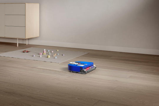
The Dyson Revolution: A New Era in Robot Vacuum Cleaners
🚀Take your cleaning to the next level with Dyson's 360 Vis Nav robot vacuum cleaner! The future is here and it's never been easier to keep your home spotless. #Dyson #robotvacuumcleaner
View On WordPress
#3D mapping#AI#dual-link suspension#dyson#Dyson 360 Vis Nav#Dyson Purifier#Dyson Submarine#future of robot vacuums#HEPA filtration#Hyperdymium motor#LED light ring#MyDyson app#Piezo sensor#robot vacuum#smart navigation#vacuum technology
1 note
·
View note
Text


youtube
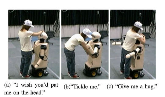
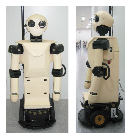
Robovie-IIF (2005) by Takahiro Miyashita, ATR, Kyoto, Japan. Robovie-IIF's skin is a sensor network with 274 3×3cm, or 5×5cm piezo-film (PVDF film) touch sensors, embedded in soft silicone rubber.
"The Osaka-based Advanced Telecommunications Research Institute (ATR) has developed a crowd-monitoring humanoid robot that recognizes when people are lost and helps them find their way. In a series of demonstrations … a souped-up version of ATR's Robovie humanoid robot monitored people as they passed through a 100 square meter (1,076 sq ft) section of the Universal Citywalk Osaka shopping center. Relying on data from 16 cameras, 6 laser range finders and 9 RFID tag readers installed in and around the area, the robot was able to watch up to 20 people at a time, pinpoint their locations to within a few centimeters, and classify each individual's behavior into one of 10 categories (waiting, wandering, walking fast, running, etc.). Whenever Robovie spotted people who looked disoriented, the child-sized droid wheeled up to them and asked, "Are you lost?" If so, the robot provided simple directions to the destination and pointed the way. If not, the robot proceeded to recommend nearby shops and restaurants." – Robovie droid helps lost shoppers, pink tentacle.
20 notes
·
View notes
Text
An international research group has engineered a novel high-strength flexible device by combining piezoelectric composites with unidirectional carbon fiber (UDCF), an anisotropic material that provides strength only in the direction of the fibers. The new device transforms kinetic energy from the human motion into electricity, providing an efficient and reliable means for high-strength and self-powered sensors. Details of the group's research were published in the journal Small on Dec.14, 2023. Motion diction involves converting energy from the human motion into measurable electrical signals and is something crucial for ensuring a sustainable future.
Read more.
8 notes
·
View notes
Text
Achieve Precision Motion Control with Robust Piezoelectric Bimorphs
A piezoelectric bimorph is a specialized bending actuator or sensor comprised of two bonded piezoelectric ceramic layers separated by an inner passive layer. When subjected to an electric field, one ceramic layer expands while the other contracts due to the converse piezoelectric effect, causing the composite to bend. This bending motion can be harnessed for precision actuation and vibration control applications.

The central passive layer, typically made of a metal or polymer, provides mechanical support and prevents electrical shorting between the two active piezo layers. The ceramic layers are poled during manufacturing to align their electric dipole moments in opposite axial directions. When an electric field is applied across the bimorph’s thickness, one layer expands longitudinally while the other contracts, resulting in a net bending displacement perpendicular to the field direction.
For More Information Please visit, pzt bimorph
Bimorphs exhibit higher generative force compared to unimorphs, but slightly lower displacement range. The three-layer symmetric configuration also provides enhanced thermal stability. Bimorphs are engineered to resonance in desired frequency ranges from ~5 Hz up to hundreds of kHz depending on the materials and construction.
Key bimorph advantages:
Large bidirectional bending motions possible up to ±1 mm range.
Fast response times in milliseconds or less.
Generative force up to 100s of newtons.
Low operating voltages, often less than 30V.
Tailorable dynamics via materials selection and dimensions.
Compact, simple construction suitable for arrays.
Lower cost compared to stacks.
Consistent performance over billions of cycles.

Bimorph applications include:
Precision positioning stages and manipulators.
Piezoelectric motors and pumps.
Speakers and headphones due to good audio range response.
Vibration suppression and shock absorption.
Energy harvesting from vibrations and motion.
Overall, the bimorph configuration offers a balanced set of advantages for electromechanical transduction compared to other multilayer piezo options. With thoughtful design, bimorphs enable highly adaptable and robust motion control, acoustic, and sensor solutions.
2 notes
·
View notes
Text
Elmalo, let's move forward with scoping a full pilot buildout—starting with the v1 Mars Habitat Monitor. This path offers a compelling, high-stakes testbed for the Iron Spine system and allows us to prototype under extreme, failure-intolerant conditions. Designing for Mars pushes the architecture to its limits, ensuring resilience, autonomy, and layered intelligence from the outset.
🚀 v1 Mars Habitat Monitor – Pilot Buildout
🔧 Environmental Design Requirements
Radiation-Hardened Components: Select radiation-tolerant MCU/FPGA and sensor components (e.g., RAD750 derivatives or Microsemi FPGAs).
Thermal Regulation: Passive and active methods (phase-change materials, aerogels, thin-film heaters).
Dust Protection: Hermetically sealed enclosures with electrostatic or vibrational dust mitigation (similar to the Mars 2020 rover’s approach).
Power Constraints: Solar panels + supercapacitors for charge buffering, with ultra-low power idle modes.
Communications Delay Tolerance: Incorporate DTN (Delay-Tolerant Networking) bundles for relayed Earth-Mars messaging.
🧠 Sensor Suite
Life Support Monitoring:
CO₂ / O₂ / CH₄ levels
Humidity / Temperature / Pressure
Structural Integrity:
Microfracture sensors (piezo-acoustic or fiber optic strain gauges)
Vibration analysis (accelerometers/IMUs)
Radiation Exposure:
Ionizing radiation detectors (Geiger-Müller tubes or RADFETs)
Environmental:
Dust density (LIDAR or IR scattering)
UV exposure, ambient EM fields
🧩 System Architecture
Sensor Synchronization:
Use local PTP clocks with oscillator drift correction from a central unit
Redundant clocks for fault detection
Data Fusion Layer:
Edge-level Kalman filters for each sensor type
Onboard anomaly detection with TensorRT-lite or ONNX models for pattern deviation
Edge Inference:
PyTorch Mobile or ONNX on an ARM-based SOM (e.g., NVIDIA Jetson Nano with radiation shielding)
Data Relay and Storage:
Store all telemetry in redundant onboard buffers
Use prepackaged DTN bundles and error-correcting transmission protocols to transmit during windowed comms
Digital Twin Integration:
Each monitor syncs with a simulated Mars habitat replica in Earth orbit or ground control
Dashboard via Prometheus/Grafana or a bespoke Unity/Unreal-powered 3D monitoring console
⚙️ Resilience & Power
Watchdog Timers: Auto-reset on failure, with a secondary power rail for minimal heartbeat signal
Power Monitoring: Real-time tracking of draw, supercapacitor status, and solar charge
Failover States: Downgraded functionality tier for power preservation and sensor core redundancy
Would you like a modular breakdown of the above, suitable for PCB design, mechanical housing, and software stack implementation? Or perhaps a visual mission profile that tracks expected operational phases, anomaly response, and maintenance cycles for the Mars system?
Let’s make this pilot the template for Iron Spine’s interplanetary leap.
0 notes
Text
Enhance Operational Efficiency with High-Performance Numeric Keypads

In industrial and commercial sectors where precision and resilience are non-negotiable, numeric keypads serve as critical interfaces for data entry, equipment control, and security systems. However, standard keypads often struggle with wear, environmental exposure, or complex maintenance. Our 13x4 Aluminium Piezo Keypad IP68 KPF34 redefines durability without compromising functionality, offering a seamless blend of engineering excellence and practicality for mission-critical applications.
Traditional keypads with mechanical switches are prone to degradation from dust, moisture, and frequent use. Our 13x4 Aluminium Piezo Keypad IP68 KPF34 eliminates these vulnerabilities through piezo switch technology, which uses advanced pressure-sensitive sensors instead of moving parts. This innovation ensures:
• IP68 Protection: Sealed against water, dust, and contaminants, ideal for outdoor, marine, or manufacturing settings.
• Zero Maintenance: A single-piece aluminum construction and potted rear switches prevent corrosion and mechanical failure.
• Enhanced Longevity: Engineered for high-cycle use, reducing replacement costs and downtime.
Key Features Tailored for Demanding Applications
1. 3x4 Keypad Layout with 12 Keys ,Optimized for numeric input in logistics, HVAC, or access control systems, the compact design maximizes workspace efficiency.
2. Matrix Keypad Output ,Simplifies integration with industrial PLCs, HMIs, or IoT devices through standardized matrix signaling.
3. Solid Aluminium Construction
A monolithic aluminum body withstands impacts, extreme temperatures, and prolonged UV exposure, ensuring reliability in harsh climates.
4. Ruggedized Switching Technology ,Piezo elements eliminate contact bounce and wear, delivering consistent performance even after millions of actuations.
Streamline Your Equipment with Versatile Deployment Solutions
Unlike bulky or fragile alternatives, the 13x4 Aluminium Piezo Keypad IP68 KPF34 combines lightweight design with industrial-grade durability. Its IP68-rated sealing and corrugated aluminum surface resist abrasion, making it suitable for:
• Outdoor Terminals: Weatherproof operation in transportation or energy sectors.
• Food Processing: Hygienic, easy-to-clean surfaces compliant with sanitation standards.
• Security Systems: Tamper-resistant interfaces for restricted access zones.
By integrating this keypad, businesses reduce long-term maintenance budgets while enhancing equipment lifespan—a strategic advantage for ROI-focused operations.
For enterprises prioritizing reliability, compliance, and operational continuity, standard keypads fall short. The 13x4 Aluminium Piezo Keypad IP68 KPF34 delivers unmatched performance in demanding environments, backed by scalable integration options and industry-leading longevity.
Contact our team to discuss custom configurations or bulk procurement. Visit our website to explore the 13x4 Aluminium Piezo Keypad IP68 KPF34 and discover how precision-engineered numeric keypads can transform your workflow efficiency.
0 notes
Text
For sell New Mutoh XpertJet 1462UF UV-LED flatbed printer
For sell New Mutoh XpertJet 1462UF UV-LED flatbed printer
Price: $24,498.00 Find more mutoh flatbed printers at www.indraminer.shop
The MUTOH XpertJet 1462UF UV-LED flatbed printer with a moving gantry features a large 55″ x 27″ printable surface area, two 4″ UV-LED lamps, two piezo drop on demand dual print heads in a staggered configuration, and will print on objects up to 5.9″ thick. Legally prints ADA compliant braille and 2.5D layered prints to create fine textured art to add value to any print job. Tie that in with MUTOH’s Local Dimming Control Technology, and you now have the ability to add glossy finishes easily in one pass. With MUTOH’s “Made in Japan Quality” and proprietary features such as the Automatic Nozzle Detection Unit and the Area Select function, the MUTOH XPJ-1462UF is the ideal printer for any print shop looking for reliability, high quality, and fast speeds.
Features 55″ x 27″ Printing Area Two 4″ UV-LED Lamps Staggered Dual Print Head Configuration Up to 5.9″ Thick Material Height Laser Height Detection Sensor Rigid Chassis and Bed Laser Etched Guide-Lines 4-Zone Vacuum Table Unit Pre-Drilled Jig Holes Ferromagnetic Table Bed Comes Pre-Assembled Available with UH-21 hard/rigid ink, 6 colors CMYK+White+Varnish Automatic Nozzle Check Unit Nozzle Area Select.
0 notes
Text
How Piezoelectric Disc Are Transforming Self-Powered Devices?
As the world moves towards sustainable energy solutions, scientists and engineers are constantly exploring innovative ways to generate power efficiently. One such breakthrough technology is the piezoelectric disc, which plays a crucial role in energy harvesting. These discs, made from piezoelectric materials(https://piezodirect.com/piezo-disc-actuators/), convert mechanical stress—such as vibrations, pressure, or motion—into electrical energy.With rising demand for self-powered sensors, smart devices, and renewable energy solutions, piezoelectric disc technology is becoming a game-changer.
1 note
·
View note
Text
I know this example I’m about to give is not an acronym as such, but biologists/ physiologists are also funny with naming things (when they also don’t suck). In the body, there’s this force sensor called Piezo, derived from the Greek ‘to press’.
Well, because it’s ‘force sensing,’ biologists cannot resist making Star Wars references. So a molecule that activates Piezo1 has been aptly named ‘Yoda1’, whereas ‘Dooku1’ inhibits.
Imagine the chaos that ensued when Piezo1 scientists were at a conference with me on May 4th…
Backronyms
Physicists suck at naming things (I can say this because I'm a MechE and I have had to deal with so many physicists), but occasionally they have a stroke of brilliance. Like, a friend of mine worked on a dark matter detector called DarkSide. That's so goofy that it wraps back around to good.
Anyway, there's this superconducting fusion reactor in france called WEST. It's notable for having first-wall shielding tiles (the innermost surface of the vacuum chamber, directly facing the fusion plasma) entirely made of tungsten.
There are a lot of materials used for plasma-facing components – tungsten, molybdenum, graphite, beryllium, various composites and combinations of the above – but it's pretty rare for a reactor to go full tungsten. It can take extremely high temperatures, but it's brittle and expensive, and "high-Z" (high molecular weight) impurities in the plasma cause their own issues. So, the main purpose of WEST is to investigate the viability of an all-tungsten first wall and divertor.
To that end, they tortured an acronym until they got it to work:
Tungsten Environment in Steady-state Tokamak
Or "WEST"
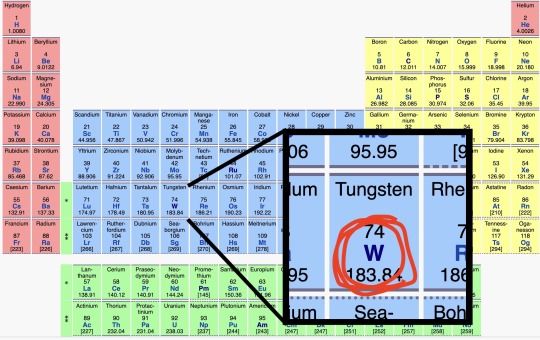
Get it?
GEW IW??
#I hate piezo1 I’m like the only person in the institute that hates it#but it’s great for the puns#piezo1#may the fourth be with you#star wars
978 notes
·
View notes
Text
0 notes
Text


Nerd Herd (AKA “toaster-bots”) by Maja Matarić (1992), MIT AI Laboratory, Cambridge, MA. Known as "toaster-bots" due to their resemblance to the eponymous kitchen appliance, they also have bread themed names including Brioche, Zwieback and Wonder. In the lower photo three of them form a chain, while another returns with a puck after an excursion around the pen. “Each robot is a 12”-long four-wheeled base, equipped with a forklift for picking up, carrying, and stacking pucks, and a radio transceiver for inter-robot communication and data collection. Each of the robots is also equipped with piezo-electric bump sensors, and infra-red collision and puck detection sensors.” – Controlling a Mobile Robot Herd: Theory and Practice, by Maja Matarić.
“Robots in The Nerd Herd have definite, if simple, sets of goals and subgoals - for instance, Bring home as many pucks as possible. Beyond that, Mataric´ has built reinforcement schemes into every robot, giving them internal mechanisms for "liking" or "disliking" things. When they do something well, such as picking up a puck, they get positive reinforcement and repeat that action in the future. When they do something badly, such as colliding with a wall, they get negative reinforcement and avoid that in the future. … As I watch them running around inside the pen, it's hard not to wonder how much of Mataric´'s own biases about society and social behavior affect the qualities she programs into her robots. "Ah," she laughs at the obvious attempt at a little pop psychology. "Does my desire for distributed systems mean that I don't believe in any type of centralized authority? Let's just say that I'm not given to taking authority easily. I am something of an iconoclast, and in general the approaches I've taken have been iconoclastic." Regardless of the politics involved, the result is a group of robots that is able to think locally but act globally.” – Herd mentality, by Jerry Shine, WIRED magazine, June 1996.
9 notes
·
View notes
Text
How Do Aircraft Weighing Scales Enhance Aviation Safety and Efficiency?
Accurate weight and balance data are crucial for the aviation industry. Without precise measurements, aircraft performance and safety could be compromised. General Electrodynamics Corporation (GEC), a leader in the field, has been at the forefront of designing and manufacturing aircraft weighing scales for over 40 years. Leveraging cutting-edge technologies and patented designs, GEC offers unparalleled accuracy and reliability in the industry. This article delves into the importance, features, and benefits of aircraft weighing systems, highlighting why GEC is a trusted name in the aviation sector.
Why Are Aircraft Weighing Scales Necessary?
Ensuring Proper Weight Distribution
Aircraft Weighing Scales provide accurate weight distribution data, which is critical for maintaining the aircraft's center of gravity. Imbalances can lead to issues during takeoff, flight, and landing, increasing the risk of accidents.
Regulatory Compliance
Aviation regulatory bodies, such as the Federal Aviation Administration (FAA), require aircraft operators to maintain detailed weight and balance records. Using aircraft scales ensures compliance with these strict regulations.
Optimizing Performance and Fuel Efficiency
Accurate weight data allows airlines and operators to optimize fuel loads and performance. This results in cost savings and reduced environmental impact, benefiting both the operator and the planet.
What Makes GEC’s Aircraft Weighing Systems Stand Out?
1. Patented Piezo-Electric Sensor Technology
One of GEC’s standout features is its innovative piezo-electric sensor design. This technology ensures unmatched accuracy and repeatability, setting GEC’s aircraft weighing systems apart from competitors.
2. Wide Range of Applications
From ultra-light unmanned aerial vehicles (UAVs) to massive Airbus A380s, GEC offers a diverse range of aircraft scales tailored to various needs. Their systems are designed to accommodate different aircraft types, ensuring versatility across the aviation industry.
3. Durable Materials and Advanced Engineering
GEC uses high-quality composite materials and advanced technologies in their designs. This focus on durability and longevity ensures that the scales perform reliably even in challenging environments.
4. Continuous Innovation
With a robust investment in research and development, GEC consistently introduces newer technologies and systems to meet evolving industry demands. This commitment to innovation keeps their products ahead of the curve.
How Are Aircraft Weighing Scales Used?
Aircraft weighing scales are employed in several scenarios, including:
Routine Maintenance Aircraft are periodically weighed to ensure their weight remains within acceptable limits. This is especially important after modifications or repairs.
Fleet Management Airlines use weighing systems to monitor the weight and balance of their fleets, ensuring operational efficiency and compliance with regulations.
Manufacturing and Testing During manufacturing, aircraft are weighed to validate design specifications. Similarly, testing during prototyping relies heavily on accurate weighing data.
Specialized Operations Military and cargo aircraft require precise weight measurements for mission-specific configurations. GEC’s systems cater to these specialized needs.
What Are the Types of Aircraft Weighing Systems Offered by GEC?
GEC provides a variety of aircraft Weighing Systems designed to meet diverse operational requirements. These include:
1. Portable Platform Scales
Portable platform scales are ideal for quick and efficient weighing. Their lightweight design and ease of transport make them perfect for field operations.
2. Low-Profile Platform Scales
These scales are designed for aircraft with low ground clearance. GEC’s low-profile models ensure accurate measurements without requiring extensive setup.
3. Onboard Weighing Systems
For operators seeking real-time weight data during flight, onboard systems are an invaluable tool. These systems integrate seamlessly with the aircraft’s existing infrastructure.
4. Advanced Wireless Systems
Wireless systems eliminate the need for extensive cabling, reducing setup time and improving operational efficiency. GEC’s wireless scales are known for their reliability and user-friendly design.
What Are the Benefits of Using GEC’s Aircraft Scales?
1. Enhanced Safety
Accurate weight and balance data ensure that aircraft operate within their safety parameters, reducing the risk of incidents.
2. Time Efficiency
GEC’s systems are designed for quick setup and operation, minimizing downtime during weighing procedures.
3. Cost Savings
By optimizing weight distribution and fuel efficiency, GEC’s aircraft weighing scales contribute to significant cost reductions for operators.
4. Long-Term Durability
Engineered with high-quality materials, GEC’s scales offer exceptional durability, providing long-term value for customers.
5. Customization
GEC offers tailored solutions to meet specific customer requirements, ensuring that their systems align with unique operational needs.
Why Choose General Electrodynamics Corporation?
GEC’s reputation as a leader in the aircraft scales market is built on decades of excellence, innovation, and customer satisfaction. Here’s why aviation professionals trust GEC:
Proven Track Record: Over 40 years of experience in designing and manufacturing aircraft weighing systems.
Global Reach: GEC’s products are used by customers worldwide, from commercial airlines to military organizations.
Customer Support: Comprehensive support services ensure that customers receive the assistance they need, from installation to maintenance.
FAQs About Aircraft Weighing Scales and Systems
Q: How often should aircraft be weighed? A: Aircraft should be weighed after significant modifications, during routine maintenance, or as required by regulatory bodies.
Q: Can GEC’s systems handle large aircraft like the A380? A: Yes, GEC offers scales capable of weighing large aircraft, including the Airbus A380.
Q: What factors affect the accuracy of aircraft weighing scales? A: Factors such as calibration, environmental conditions, and proper usage can impact accuracy. GEC’s patented technologies ensure consistent performance.
Q: Are GEC’s systems portable? A: Many of GEC’s aircraft scales, such as their portable platform scales, are designed for easy transport and setup.
Conclusion
Aircraft weighing scales are an indispensable tool for ensuring the safety, performance, and efficiency of aviation operations. General Electrodynamics Corporation has set the standard for accuracy, durability, and innovation in the industry. With a wide range of aircraft weighing systems, GEC caters to the diverse needs of aviation professionals worldwide. Whether you operate UAVs or large commercial jets, GEC’s aircraft scales are a trusted solution for all your weight and balance needs.
Explore GEC’s advanced aircraft weighing solutions today and experience the difference in quality and precision.
0 notes
Text
Global Piezoelectric Devices Market
The Global Piezoelectric Devices Market is anticipated to grow from USD 33.2 billion in 2023 to USD 53 billion in 2030 at a CAGR of 7.4% during the forecast period from 2025 to 2030.
Explore more-https://www.vynzresearch.com/ict-media/piezoelectric-devices-market/request-sample
Key drivers of this market include the push for miniaturization of devices, the need for energy-efficient and reliable sensors, and advancements in piezoelectric materials like ceramics and composites. These materials are crucial due to their high piezoelectric constants and electromechanical coupling coefficients, which make them ideal for applications in sensors, actuators, and transducers.
Major players of Piezoelectric Devices Market are CeramTec GmbH (Germany), Physik Instrumente (PI) GmbH & Co. KG. (Germany), CTS Corporation (US), Kistler Group (Switzerland), piezosystem jena GmbH (Germany), Aerotech Inc. (US), APC International, Ltd., (US), Piezo Technologies (US), Mad City Labs, Inc. (US).
VynZ Research
9960288381
0 notes
Text
Arduino Plug and Make Kit: Abstandskontrolle mit Alarmfunktion

In diesem Beitrag erfährst du Schritt-für-Schritt, wie man eine Abstandskontrolle mit Alarmfunktion mit dem Arduino Plug and Make Kit aufbaut und programmiert. Das neue Arduino Plug and Make Kit habe ich dir bereits im gleichnamigen Beitrag Arduino Plug and Make Kit: Was ist drin und wie benutzt man es? vorgestellt. https://youtu.be/YL-enMuAMBc Das Arduino Plug and Make Kit bekommst du derzeit für knapp 90€ inkl. Versandkosten im offiziellen Shop. Aus diesem Kit verwenden wir den Arduino UNO R4 WiFi, den Laser Distanzsensor, den Piezo Buzzer, das 8fach LED Modul sowie den Rotary Encoder. Zusätzlich benötigen wir noch die Modulino Base, ein paar Schrauben & Muttern sowie die Qwiic Anschlusskabel. Das alles ist im Kit enthalten, du benötigst quasis nurnoch deinen PC und einen kleinen Kreuzschraubendreher.

Arduino UNO R4 WiFi
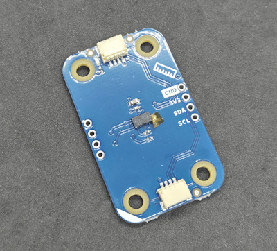
ToF - Distance Sensor
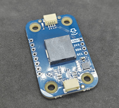
Buzzer

8fach LED Modul
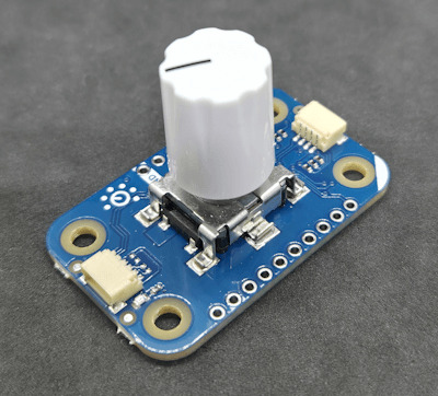
Rotary Encoder
Wie soll das kleine Projekt funktionieren?
Über den Distanzsensor messen wir dauerhaft einen Abstand zu einem Gegenstand (Wand, Türrahmen etc.) wenn dieser Wert unterschritten wird, dann wird ein Alarm (akustisch und visuell) ausgegeben. Über den Rotary Encoder und der 8x12 LED Matrix vom Arduino UNO R4 WiFi stellen wir den Abstand ein. Dabei wird, wenn wir eine Klick-Aktion am Rotary Encoder ausführen, der aktuelle Wert auf der Matrix ausgegeben.
Benötigte Ressourcen für den Aufbau
Für den Aufbau der Schaltung benötigst du: - einen Arduino UNO R4 WiFi, - ein USB-C Datenkabel, - ein ToF / Laser Distanzsensor, - ein Rotary Encoder, - ein 8fach LED Modul, - ein Piezo Buzzer, sowie - ein paar Schrauben und - einen kleinen Kreuzschraubendreher

Arduino Plug and Make Kit - Komponenten für das Alarmprojekt Ausgenommen vom Kreuzschraubendreher ist alles im Arduino Plug and Make Kit enthalten!
Programmieren der Modulino Sensoren / Aktoren in der Ardino IDE
Das Kit ist ausgelegt, um in der Arduino IDE programmiert zu werden. Du musst jedoch zuvor den Boardtreiber für den Arduino UNO R4 WiFi und die Bibliothek für die Modulino Sensoren / Aktoren installieren.

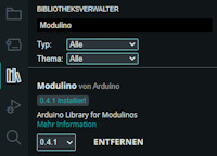
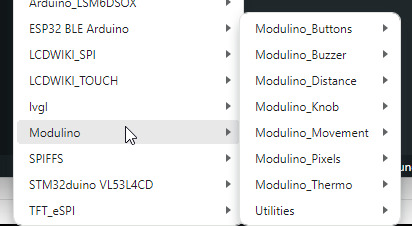
Zu der Bibliothek Modulino erhältst du zu jedem Sensor / Aktor aus diesem Kit ein ausführliches Beispiel und in der offiziellen Dokumentation nochmal viel mehr Informationen. Programm - Durchgangsalarm mit dem Arduino Plug and Make KitHerunterladen Schritt 1 - Importieren der Bibliotheken und erzeugen der Objektinstanzen Im ersten Schritt importieren wir die benötigten Bibliotheken für das Projekt. (Zur Vorbereitung hatten wir bereits die Modulino Bibliothek installiert.) //Bibliothek zum steuern / auslesen //der Modulino Sensoren / Aktoren #include //Bibliotheken zum steuern der //8x12 LED Matrix am Arduino UNO R4 WiFi #include "ArduinoGraphics.h" #include "Arduino_LED_Matrix.h" Anschließend erzeugen wir uns die Objektinstanzen für unser Projekt. //Objektinstanz der LED-Matrix ArduinoLEDMatrix matrix; //Objektinstanzen der Sensoren / Aktoren ModulinoDistance distance; ModulinoPixels leds; ModulinoKnob knob; ModulinoBuzzer buzzer; Schritt 2 - Initialisieren der Kommunikation mit den Sensoren / Aktoren Nachdem die benötigten Bibliotheken installiert und die Objekte erzeugt wurden, müssen wir die I2C Kommunikation starten. Dazu müssen wir bei den Modulinos lediglich die Funktion "begin" aufrufen. Dieses macht die verwendung dieser Module sehr einfach und komfortabel. void setup() { //beginn der seriellen Kommunikation Serial.begin(9600); //beginn der Kommunikation mit der LED-Matrix matrix.begin(); //Vorbereiten der Kommunikation mit den Modulino //Sensoren / Aktoren Modulino.begin(); //Initialisieren der I2C Kommunikation mit den //Sensoren / Aktoren distance.begin(); leds.begin(); knob.begin(); buzzer.begin(); //Startwert des Rotary Encoders / Knob auf 0 setzen. knob.set(0); } Zusätzlich setze ich den Wert des Rotary Encoders auf 0. Schritt 3 - Auslesen der Sensorwerte und erzeugen des Alarms Im dritten Schritt lesen wir in der Funktion "loop" zunächst den Wert des Rotary Encoders aus und multiplizieren diesen mit 10. Damit müssen wir nicht so viele Umdrehungen machen damit ein Abstand eingestellt werden kann, wenn du kleine Schritte benötigst dann musst du diesen Wert anpassen. //lesen des aktuellen Wertes vom Rotary Encoder //der Wert wird mit 10 multipliziert und abgespeichert int16_t distanceForAlarm = knob.get() * 10; Wenn der Rotary Encoder gedrückt wird, können wir eine zusätzliche Aktion ausführen, in diesem Fall wird der Wert auf der 8x12 LED Matrix angezeigt. //Wenn der Rotary Encoder gedrückt wird, dann... if (knob.isPressed()) { //Aufrufen der Funktion zum Anzeigen des aktuellen //wertes des Rotary Encoder. displayKnobValue(distanceForAlarm); } Wenn der Distanzsensor erkannt wurde, dann lesen wir einen Messwert und vergleichen diesen mit dem eingestellten Abstand vom Rotary Encoder. if (distance.available()) { //Messwert abrufen und abspeichern int measure = distance.get(); //Wenn der messwert kleiner als der abgespeicherte //Wert für den Alarm ist, dann... if (measure < distanceForAlarm) { //Ausgeben des Textes "Alarm" auf der seriellen Schnittstelle Serial.println("Alarm"); //anzeigen eines visuellen Alarms über das 8fach LED Modul visualAlarm(); //ausgeben eines akustischen Alarms über das Piezo Buzzer Modul soundAlarm(); } } Am Ende legen wir noch eine kleine Pause von 20 Millisekunden ein. //eine kleine Pause von 20 ms. delay(20); Schritt 3.1 - Funktion "displayKnobValue" Die Funktion displayKnobValue zeigt den Wert des Übergebenen Parameters auf der 8x12 LED Matrix an. Sollte jedoch der Wert kleiner 0 sein, so wird eine Fehlermeldung angezeigt. /Funktion zum anzeigen eines Textes auf der //LED-Matrix. void displayKnobValue(int16_t value) { matrix.beginDraw(); matrix.stroke(0xFFFFFFFF); matrix.textScrollSpeed(50); String message = "-undefined- "; //Wenn der Wert kleiner 0 ist, dann... if (value < 0) { //erzeugen einer kleinen Fehlermeldung message = "err: val < 0"; } else { //Wenn der wert größer 0 ist, dann müssen wir //eine 12 Zeichen lange Zeichenkette erzeugen. int valueLength = String(value).length(); int partLength = (12 - valueLength) / 2; String part = ""; for (int s = 0; s < partLength; s++) { part += " "; } message = part + String(value) + part; } //ablegen der erstellten Zeichenkette in das Char-Array char text = ""; message.toCharArray(text, 13); //Ausgeben des Textes auf der LED-Matrix //Schriftgröße 4x6 matrix.textFont(Font_4x6); matrix.beginText(0, 1, 0xFFFFFF); matrix.println(text); matrix.endText(SCROLL_LEFT); matrix.endDraw(); } Schritt 3.2 - Funktion "visualAlarm" Die Funktion visualAlarm lässt die LEDs im 25ms. Intervall aufleuchten. //Funktion zum erzeugen eines visuellen Alarms mit //dem 8fach LED Modul. Die LEDs blinken im 25ms. Takt void visualAlarm() { setLEDsStatus(true); delay(25); setLEDsStatus(false); delay(25); } //Funktion zum setzen der LEDs. //Als Parameter wird der erwartete Status übergeben. void setLEDsStatus(bool on) { //Schleife über die LEDs for (int i = 0; i < 8; i++) { //Wenn die LEDs aktiviert werden sollen, dann ist //die Helligkeit auf 100 ansonsten auf 0 leds.set(i, RED, on ? 100 : 0); } //nachdem alle LEDs konfiguriert wurden, dann werden //diese Daten ausgeliefert / angezeigt. leds.show(); } Schritt 3.3 - Funktion "soundAlarm" Mit der Funktion soundAlarm wird der Piezo Buzzer angesteuert und dieser erzeugt einen hellen Ton als zusätzlichen Signal. //Funktion zum erzeugen eines Tones auf //dem Piezo Buzzer Moduls. void soundAlarm() { //die Frequenz des Tones int frequency = 440; //die Dauer int duration = 1000; //erzeugen des Tones buzzer.tone(frequency, duration); delay(50); //abschalten des Tones buzzer.tone(0, duration); delay(25); } Fertiges Projekt - Durchgangsalarm mit dem Arduino Plug and Make Kit Hier nun das fertige Projekt zum kopieren. //Bibliothek zum steuern / auslesen //der Modulino Sensoren / Aktoren #include //Bibliotheken zum steuern der //8x12 LED Matrix am Arduino UNO R4 WiFi #include "ArduinoGraphics.h" #include "Arduino_LED_Matrix.h" //Objektinstanz der LED-Matrix ArduinoLEDMatrix matrix; //Objektinstanzen der Sensoren / Aktoren ModulinoDistance distance; ModulinoPixels leds; ModulinoKnob knob; ModulinoBuzzer buzzer; void setup() { //beginn der seriellen Kommunikation Serial.begin(9600); //beginn der Kommunikation mit der LED-Matrix matrix.begin(); //Vorbereiten der Kommunikation mit den Modulino //Sensoren / Aktoren Modulino.begin(); //Initialisieren der I2C Kommunikation mit den //Sensoren / Aktoren distance.begin(); leds.begin(); knob.begin(); buzzer.begin(); //Startwert des Rotary Encoders / Knob auf 0 setzen. knob.set(0); } void loop() { //lesen des aktuellen Wertes vom Rotary Encoder //der Wert wird mit 10 multipliziert und abgespeichert int16_t distanceForAlarm = knob.get() * 10; //Wenn der Rotary Encoder gedrückt wird, dann... if (knob.isPressed()) { //Aufrufen der Funktion zum Anzeigen des aktuellen //wertes des Rotary Encoder. displayKnobValue(distanceForAlarm); } //Wenn ein ToF Sensor verfügbar ist, dann... if (distance.available()) { //Messwert abrufen und abspeichern int measure = distance.get(); //Wenn der messwert kleiner als der abgespeicherte //Wert für den Alarm ist, dann... if (measure < distanceForAlarm) { //Ausgeben des Textes "Alarm" auf der seriellen Schnittstelle Serial.println("Alarm"); //anzeigen eines visuellen Alarms über das 8fach LED Modul visualAlarm(); //ausgeben eines akustischen Alarms über das Piezo Buzzer Modul soundAlarm(); } } //eine kleine Pause von 20 ms. delay(20); } //Funktion zum anzeigen eines Textes auf der //LED-Matrix. void displayKnobValue(int16_t value) { matrix.beginDraw(); matrix.stroke(0xFFFFFFFF); matrix.textScrollSpeed(50); String message = "-undefined- "; //Wenn der Wert kleiner 0 ist, dann... if (value < 0) { //erzeugen einer kleinen Fehlermeldung message = "err: val < 0"; } else { //Wenn der wert größer 0 ist, dann müssen wir //eine 12 Zeichen lange Zeichenkette erzeugen. int valueLength = String(value).length(); int partLength = (12 - valueLength) / 2; String part = ""; for (int s = 0; s < partLength; s++) { part += " "; } message = part + String(value) + part; } //ablegen der erstellten Zeichenkette in das Char-Array char text = ""; message.toCharArray(text, 13); //Ausgeben des Textes auf der LED-Matrix //Schriftgröße 4x6 matrix.textFont(Font_4x6); matrix.beginText(0, 1, 0xFFFFFF); matrix.println(text); matrix.endText(SCROLL_LEFT); matrix.endDraw(); } //Funktion zum erzeugen eines visuellen Alarms mit //dem 8fach LED Modul. Die LEDs blinken im 25ms. Takt void visualAlarm() { setLEDsStatus(true); delay(25); setLEDsStatus(false); delay(25); } //Funktion zum erzeugen eines Tones auf //dem Piezo Buzzer Moduls. void soundAlarm() { //die Frequenz des Tones int frequency = 440; //die Dauer int duration = 1000; //erzeugen des Tones buzzer.tone(frequency, duration); delay(50); //abschalten des Tones buzzer.tone(0, duration); delay(25); } //Funktion zum setzen der LEDs. //Als Parameter wird der erwartete Status übergeben. void setLEDsStatus(bool on) { //Schleife über die LEDs for (int i = 0; i < 8; i++) { //Wenn die LEDs aktiviert werden sollen, dann ist //die Helligkeit auf 100 ansonsten auf 0 leds.set(i, RED, on ? 100 : 0); } //nachdem alle LEDs konfiguriert wurden, dann werden //diese Daten ausgeliefert / angezeigt. leds.show(); } Read the full article
0 notes