#Plaxis
Explore tagged Tumblr posts
Visit Tumblr Blog
Explore Tumblr blogs with no restrictions, modern design and the best experience.
Last Seen Tumblr Blogs


Fun Fact
The most popular pages on Tumblr are about Minecraft, GIFs, and David J. Peterson.
Text
0 notes
Text


"THE QUALITY OF THE PICTURES WAS SO GOOD. I HAD A STINT OF HAVING IT WITH ME ALL THE TIME."
PIC(S) INFO: Mega-spotlight on behind-the-scenes Polaroids of English post-rock/post-punk/experimental music group PUBLIC IMAGE LIMITED, c. 1980-'81. 📸: Jeannette Lee.
OVERVIEW: "In late 1978, one year after the tumultuous break up of the SEX PISTOLS, John Lydon (a.k.a. Johnny Rotten) launched his new band, PUBLIC IMAGE LIMITED, featuring his childhood friend Jah Wobble on bass, and Keith Levene, former guitarist for THE CLASH, on guitar. Lydon had had a rough time of it; by the time the Sex Pistols disintegrated, he had no money, no privacy thanks to the band’s enduring notoriety and no real control over his punk past (former manager Malcolm McLaren had staked claim to the SEX PISTOLS’ image, forbidding Lydon to use the name Rotten for future endeavours). As a result, he deemed that Public Image Limited would be different: a band-cum-company comprised of trusted co-collaborators.
Shortly after founding the band he approached Jeannette Lee, now best known as the co-director of iconic independent label Rough Trade Records, inviting her into the PiL fold as a “non-musical member” of the group to help with press, promotion and general administration. Thus ensued a magical period of innovation and cooperation which saw PiL rise to greater and greater heights, blazing an avant-garde, post-punk trail. Now, a new limited-edition book of Polaroid photographs taken by Lee during her three or four-year tenure with the group, and published by IDEA, sheds candid light on this formative period of the band’s history.
Lydon and Lee had met through Don Letts, the then-manager of famous punk-reggae clothing store Acme Attractions on the King’s Road (where Lee also worked), and bonded over a shared love of reggae and their north London council estate backgrounds. “He came to me and said, "I’m starting this new thing. I want to work with people that I trust. I don’t want to work with any more idiots,"" Lee recalls in an interview with Jarvis Cocker – a close friend, whom she also manages and who helped her compile the publication – for the book’s accompanying text. “There was no real job description: just like-minded people joining forces.” Alongside the key band members, these included Don Letts, Sheila Rock, Judy Nylon and Plaxy Locatelli, among others, all of whom set up office in Lydon’s house in Gunter Grove, between Fulham and the King’s Road, and spent their days, in Lee’s words, "making manifestos and then living according to them."
It is in this intimate setting that many of Lee’s pictures are staged, taken from 1980 onwards, after the purchase of her Polaroid SX-70 camera on a trip to New York. “The quality of the pictures was so good. I had a stint of having it with me all the time. Taking pictures everywhere I went,” she tells Cocker. Lee was a natural photographer, her snapshots rendered in dreamy hues and boasting compelling compositions. Some of the images from the book will be recognisable to PiL fans – such as the brilliant photograph of Lydon gazing furtively into a spiderweb-etched mirror, which was used as the cover for the "Flowers of Romance" single – while many more have never been seen, and offer viewers wonderful insight into the very private world of PUBLIC IMAGE LIMITED. There’s a picture of one member tenderly clasping a puppy, one of Levene sitting in front of a strawberry milkshake, traces of its froth forming a moustache across his top lip, another of Lee and a boater-topped Lydon grinning goofily into the camera: the softer, sillier side of punk."
-- ANOTHER MAG, "Behind-the-Scenes Polaroids of Public Image Limited’s Heyday," by Daisy Woodward, c. May 2017
Source: www.anothermag.com/art-photography/9825/behind-the-scenes-polaroids-of-public-image-limiteds-heyday.
#PUBLIC IMAGE LTD.#PUBLIC IMAGE LTD#PUBLIC IMAGE#PUBLIC IMAGE LIMITED#Photography#Experimental Music#1981#Keith Levene#Jeannette Lee#Post-punk#Flowers of Romance 1981#Experimental#Flowers of Romance Sessions#Don Letts#PUBLIC IMAGE LTD. Flowers of Romance#PUBLIC IMAGE LTD Flowers of Romance#Polaroid photography#80s Style#Polaroid#1980s#Post-rock#John Lydon#Polaroids#PiL#Flowers of Romance#Polaroid Photos
26 notes
·
View notes
Text
Top Geotechnical Software Tools You Should Know
In geotechnical engineering, the right software makes all the difference. These tools help engineers analyze soil, tunnels, slopes, and foundations with better accuracy and speed.
Our latest infographic covers the most popular tools used today — including PLAXIS, ABAQUS, FLAC, and more.
Whether you're a student, researcher, or professional, mastering these tools can boost your skills and open new career opportunities.
✅ Learn more in our latest blog: 👉 Finite Element Analysis in Geotechnical Engineering
0 notes
Text

Geotechnical Engineering Assignment Help: Expert Assistance for Better Learning
In very simple terms, geotechnical engineering is about the behavior and study of the soil, the rocks in connection with construction activity. This will also form part of designing some foundations, and tunnels and some dams or related structures which actually require stability with the ground in question. On the whole it becomes very puzzling for any student to clearly understand the theory of geotechnical engineering while trying to provide solutions for each assignment. That is why the Tutors Help offers professional assistance in geotechnical engineering assignments to make studying easier and result-oriented.
What is Geotechnical Engineering?
Geotechnical engineering is an evaluation of soil and the characteristics of the rocks that lead to safe, stable construction in the engineering aspects. This aspect consists of:
Soil Mechanics - The composition, strength, and behavior of the soil under given conditions of study
Rock Mechanics - Engineering application and related properties of rock stability.
Foundation Engineering: Foundation design of buildings, bridges, and other structures.
Slope Stability Analysis: Landslide risk and ground failure.
Earthquake Engineering: Structural impact from seismic activities.
These are quite analytical and mathematical in nature, with very extensive practical applications. Geotechnical engineering assignments tend to be quite complex for the students.
Problems Faced by Students with Geotechnical Engineering Assignments
Complex Theories and Formulas: Various principles of soil and rock mechanics should be understood. These principles generally involve very extensive calculations.
Field Tests and Data Interpretation: Assignments involving real soil test results may become difficult.
Knowledge of Software Packages: In a geotechnical problem, usually, specific softwares such as PLAXIS, GeoStudio, and AutoCAD have to be used; students may be unfamiliar with this.
Time Constraints: The number of assignments and deadlines makes it hard to focus on geotechnical engineering projects.
How The Tutors Help Supports Students
The Tutors Help helps its students to resolve the above issues and to finish their geotechnical engineering assignment effectively. What services we can provide here:
Professional help from civil and geotechnical experts with an aptly accurate, well-researched solution to all of them.
Solutions will be specifically custom-made based on the necessities and according to university requirements of your respective assignment.
Explanation Step by step: We provide you with detailed explanations for each and every calculation and concept so that you understand the subject well.
Non-plagiarism content: Original work and very well verified in terms of quality.
Commitment towards Deadlines: We do understand the priority given toward deadlines and ensure that assignments are submitted prior to the estimated time.
Reasonable prices: All our services are pocket-friendly and allow every student to get expert help.
How to Get Geotechnical Engineering Assignment Help from The Tutors Help
Getting started is easy:
Submit Your Assignment: Share the topic, guidelines, and deadline with us.
Quote: Get an accurate and very affordable price for our work.
Assistance: Our experts will complete your task effectively while maintaining accuracy and quality
Review and Learn: Enhance your geotechnical knowledge and skills by using our final solutions.
Final Thoughts
Geotechnical engineering is one of the important disciplines requiring strong technical knowledge along with problem-solving skills. If you face any kind of problem regarding your assignments, then The Tutors Help is here to guide you with professional help and quality solutions.
Do not get worried; just try to achieve The Tutors Help today for professional help toward acing those assignments on geotechnical engineering!
0 notes
Text
youtube just suggested me Green Stuff's World new plaxi mold. Oh Valaya! Shut up brain. Now I will want to make my own old school sculpted minis.
0 notes
Text
Unlocking the Future of Civil Engineering: Online Courses at Civilera

In the rapidly evolving field of civil engineering, continuous learning and skill enhancement are paramount. With technological advancements and increasing project complexities, civil engineers must stay updated with the latest tools, techniques, and software. Enter Civilera, a leading platform offering comprehensive online civil engineering software courses designed to equip engineers with the knowledge and skills they need to excel in the modern world.
Why Online Courses?
Online courses offer unparalleled flexibility and accessibility. For working professionals, students, or anyone looking to upskill, the ability to learn at one’s own pace, from any location, is invaluable. Civilera leverages this flexibility, providing a range of courses that cater to various aspects of civil engineering.
Key Features of Civilera’s Courses
Comprehensive Curriculum: Civilera’s courses cover a wide array of topics essential for civil engineers. From structural analysis and design to project management and BIM (Building Information Modeling), the curriculum is designed to provide a holistic understanding of civil engineering software.
Expert Instructors: The courses are taught by industry experts and seasoned professionals who bring real-world experience into the virtual classroom. Their insights and practical knowledge help bridge the gap between theory and practice.
Interactive Learning: Civilera emphasizes interactive and engaging learning experiences. The platform offers live sessions, Q&A forums, and practical assignments that simulate real-life engineering problems.
Certification: Upon completion of each course, participants receive a certification that is recognized in the industry. These certifications not only validate the skills acquired but also enhance the learner’s professional profile.
Up-to-date Content: The field of civil engineering is constantly evolving, and so are the tools and software used. Civilera ensures that its course content is regularly updated to reflect the latest industry trends and technological advancements.
Popular Courses at Civilera
Structural Analysis and Design with ETABS: This course dives into the use of ETABS software for analyzing and designing building structures. Participants learn about the software’s features, modeling techniques, and how to interpret analysis results to design safe and efficient structures.
Revit for BIM: Building Information Modeling (BIM) is revolutionizing the construction industry. This course teaches the fundamentals of Revit, a leading BIM software, and how to use it for creating detailed architectural and structural models.
Project Management with Primavera P6: Effective project management is crucial in civil engineering. This course covers the use of Primavera P6, a powerful project management tool, to plan, schedule, and control complex projects.
AutoCAD for Drafting and Design: AutoCAD remains a cornerstone in the field of drafting and design. This course provides a thorough understanding of AutoCAD’s functionalities, enabling learners to create precise and professional engineering drawings.
Geotechnical Engineering with PLAXIS: Focusing on geotechnical analysis, this course covers the use of PLAXIS software for simulating soil-structure interaction and performing advanced geotechnical calculations.
Benefits of Learning with Civilera
Career Advancement: Equipping yourself with advanced software skills can significantly boost your career prospects and open up new opportunities in the civil engineering field.
Hands-on Experience: The practical approach of Civilera’s courses ensures that learners gain hands-on experience, making them job-ready.
Networking Opportunities: By joining Civilera’s community of learners and professionals, participants can expand their professional network and collaborate with peers.
Conclusion
In an industry where precision, efficiency, and innovation are key, staying ahead of the curve is essential. Civilera’s civil engineering online software courses provide the perfect platform for engineers to enhance their skills, stay updated with the latest technological advancements, and achieve their career goals. Embrace the future of civil engineering with Civilera and unlock your full potential.
0 notes
Text
Program Plaxis untuk Berbagai Penelitian
Salah satu program yang bisa digunakan adalah Plaxis, program ini umumnya digunakan untuk mereka yang bergelut di bidang teknik sipil. Untuk Anda yang baru pertama kali mengenal program ini, berikut adalah beberapa penjelasan yang berkaitan dengannya. Selengkapnya pada : https://amarstatistika.com/2021/11/16/program-plaxis-untuk-berbagai-penelitian/
0 notes
Photo

Analyzing an Embankment Dam (Earthfill) using PLAXIS... تحلیل سد خاکی با نرم افزار PLAXIS ... #embankment #dam #earthfill #PLAXIS #Analyze #سد #سد_خاکی #تحلیل https://www.instagram.com/p/BnaXGOhHSoD/?utm_source=ig_tumblr_share&igshid=dunaroty3mdt
2 notes
·
View notes
Photo

* analiz hatası:( #plaxis #civilengineering #geotechnical #ankara #sketch
25 notes
·
View notes
Text
PLAXIS can be used for projects involving engineering analysis of slope stability, groundwater flow, consolidation, or a combination of these complex scenarios. Take advantage of automated techniques, data management through to analysis workflows, and access to comprehensive analysis methods to find solutions. In this webinar, you will learn:
About Bentley’s newest licensing option, the Virtuoso Subscription
Benefits of Virtuoso Subscription
Static and Dynamic Analysis in PLAXIS Register for the webinar at https://constructorsfeed.com/

#construction#civilengineering#civilengineeringbuilding#structure#concrete#buildings#civil engineering#technology#architecture#bridge
2 notes
·
View notes
Text
Top Best PLAXIS Software Training Courses Online

Need to master PLAXIS 2D or 3D geotechnical analysis? In this blog, you will learn about the best PLAXIS training courses online: live, practical, and certification courses. Are you a novice, or do you want to accelerate your expertise? Such platforms as PIGSO Learning, Udemy, Inge Expert, and Ram Cadds Campus are reviewed and compared to each other so that you could select the one that suits you best.
Read now: https://pigsolearning.com/blog/top-best-plaxis-training-courses-online/
#plaxis training#plaxis course#plaxis software training online#plaxis 3d course#plaxis 2d training course
0 notes
Text

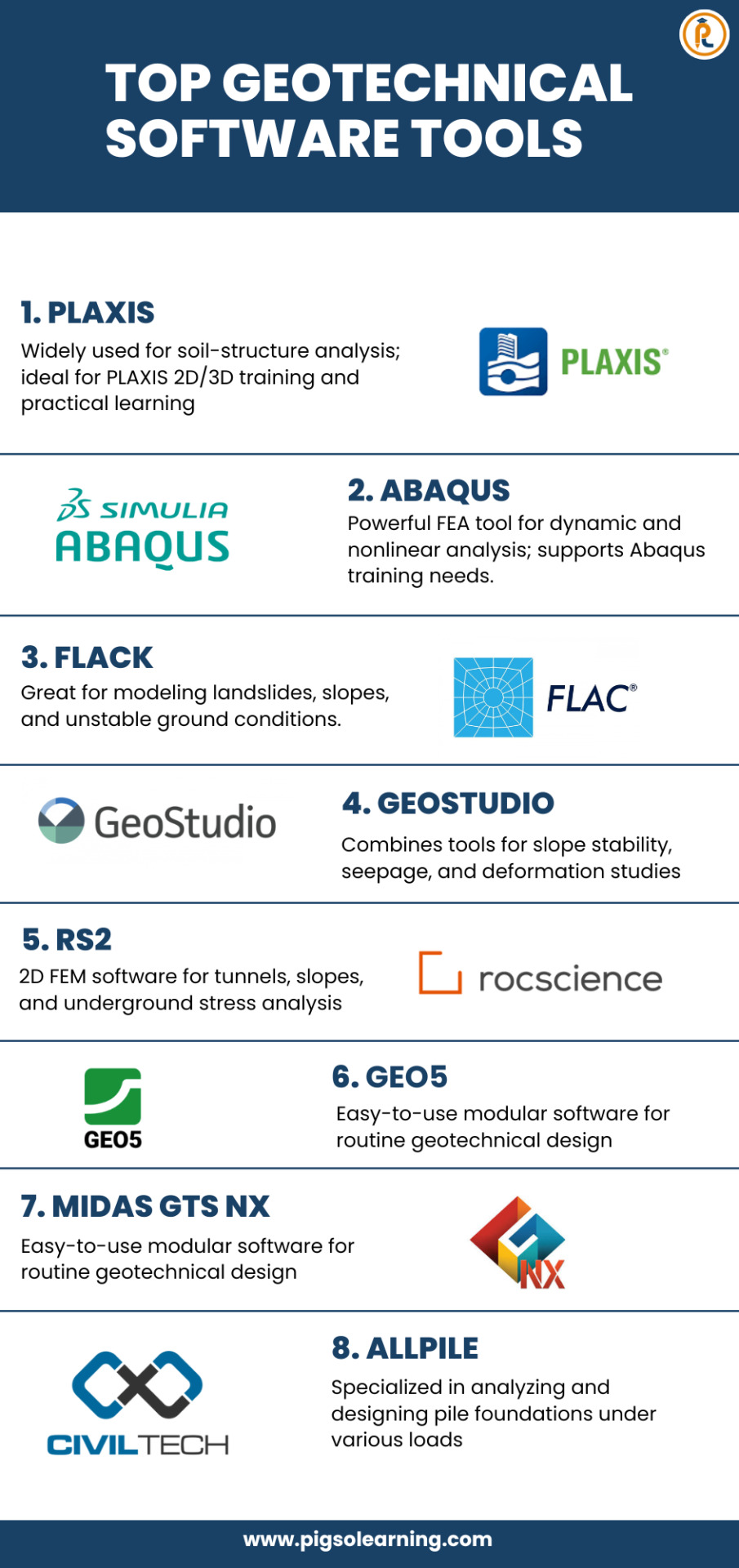
Top Geotechnical Software Tools You Should Know
In geotechnical engineering, using the right software is very important. These tools help engineers analyze soil, tunnels, slopes, and foundations more accurately and quickly. This infographic shows some of the top geotechnical software tools used today, like PLAXIS, ABAQUS, FLAC, and more.
If you're a student, researcher, or working professional, learning how to use these tools can improve your skills and open up new opportunities. Visit PIGSO LEARNING to explore expert-led courses and industry-relevant resources.
📘 Learn With Us:
Join our PLAXIS 2D/3D Training Course Online to understand soil-structure interaction and real-world analysis.
Take our Abaqus Training Course Online to learn advanced simulations and FEA methods.
Read our blog to learn more: Finite Element Analysis in Geotechnical Engineering
0 notes
Video
tumblr
Bugsona Plaxy V.1
5 notes
·
View notes
Text
Finite Element Analyses in the Tunnel: An Overview-Iris Publishers
Authored by Buse Şeyda Hocaoğlu*

Abstract
With the development of the world and human beings’ rush to get somewhere, the need for tunneling has increased. Solutions have been made with the methods of end-to-end elements searched for a more straightforward resolution and visual thinking of tunnel projects that are complex and difficult to foresee. Thanks to these methods, geotechnical problems have been more easily detecting, and solutions have been producing in a short time. Several finite element methods have been developed in line with technology development and research. In this study, Plaxis, Flac, ABAQUS, Diana, Midas GTS NX programs, which are some of these programs, were briefly introduced, and tunnel projects solved with the mentioned programs were given
Keywords:Finite element method; Tunnel project; Plaxis 2D/3D; Flac 2D/3D; Geotechnical
Introduction
The finite element method is a numerical method that thoroughly solves mixed engineering problems. It was first developed and used in 1956 for stress analysis of aircraft bodies. It has been understood that it can also solve engineering and applied sciences problems in the following years. Over the years, the finite element method and solution techniques have developed rapidly and have become one of the best methods used to solve many problems today. The method is so popular for many engineering areas because a generic computer program can only solve any problem by changing the input data. By separating it into finite elements suitable for the structure of a problem, it implements a solution method in the form of a low energy level of internal and external forces on the obtained elements and then combining these elements. As a result, the system’s features, border conditions, sudden or continuous changes of external loads can be easily examined. It is also possible to reduce the element sizes in the constant system’s desired parts for the detailed examination of a region [1,2]. It can list the advantages of finite element methods: geometry allows complex problems to be solved, easily applicable in systems with different and complex material properties, easy to include border conditions in the fundamental equations of the system, and the use of the same model to solve many problems [2]. The disadvantages of the finite element method can be listed; found that the accuracy of the result obtained depends on the accuracy of the data, that the separation of regions requires experience to get an acceptable correct result, and that the accuracy of the result obtained is observed, and that the physical problem must be investigated well [2]. The finite element method has been used for 30 years in many engineering areas and was introduced in geotechnical engineering in 1996. The most important reason for this is that geotechnical engineering has complex issues and takes time to solve them. When used correctly, this method can provide accurate results for practical geotechnical engineering problems. A good analysis allows the engineer to understand the problem better [3]. The Finite element method can be applied to any linear-elastic medium. However, it requires many limitations for the implementation of the method in geotechnical engineering problems. In the method, material behavior is formulated by associating with changes between shape changes and total stress. In contrast, in geotechnical problems, the total tensor is decompressed into cavity water pressures and effective stresses, and material behavior is often expressed in terms of effective stresses. Most of the Geotechnical problems are interacting with the structure and the ground. Therefore, in analyzing these types of problems, it is necessary to use an intermediate surface between the structure and the soil. As a result, it is required to make changes to correctly apply the finite component method in geotechnical engineering [2]. To get a realistic result in analyzing finite elements for geotechnical engineering problems, the procedures are carried out step by step (phased loading, phased excavation). There are two benefits to ensuring that analysis can be performed in stages. First, the geometry changes at each step if the analyzes add or remove the padding. The change in geometry can be modeled by adding or removing elements from the network of end elements. Secondly, in the analysis, the ground properties change at each loading stage due to the change of stresses in the soil mass [2]. As a result of the study of finite elements in geotechnical engineering problems, parameters such as stresses, cavity water pressures, lateral and vertical movements, and groundwater flow are determined [1]. Today, programs used in finite element methods are used in many areas, such as ground mechanics, fluid mechanics, aircraft engineering, nuclear engineering, rock mechanics, etc. It can be studied by selecting the program that will give the most realistic results for problems. Examples of these programs include Plaxis 2D/3D, FLAC 2D/3D, ABAQUS, Diana, Midas GTS.
Methods
Plaxis 2D/3D
Plaxis 2D/3D, one of the finite element’s programs, is a program developed to analyze geotechnical engineering problems. The program consists of an input program, calculation program where analysis is performed, output program that graphically presents the study results, and curve program that enables the creation of the desired chart with the results obtained (Figure 1). This program is used to design projects where deformation and stabilization analyzes are needed, strain-shifting, ground structure interaction, loading conditions, carrying power, consolidation, current network, ground dynamics, and material are varied and bring real-life results [4]. According to the method of finite, a continuous environment is divided into many elements. The node points on each element have a degree of freedom. During the creation of a network of finite elements in the Plaxis program, the cells are divided into triangular elements with 6 or 15 nodes (Figure 2). Even if it takes a little more time to calculate the stresses and migration surfaces more realistically, it is better to select the 15-node element. The displacement is calculated at node points during the finite element calculation [4] (Figures 1,2).
Under the main heading Plaxisde Material Sets, the floor and structural members (Soil & Interface, anchor, Beam, and Geotextile) can be defined. The Plaxis program has several floor models, such as Mohr-Coulomb (MC), Hardening Soil (Model-HS), soft Soil Creep (Model-SSC), which are widely used for analyzing floor mechanics problems (Figure 3) [4].
Flac
FLAC is a program that uses the use of a finite element type to numerically or numerically examine the mechanical behavior of continuous media in equilibrium or progressive plastic yield. In the program, creating a network of finite differences defined by the user via elements can detect the behavior of materials such as ground and rock at the level of plastic flux. Every element behaves by the previously specified linear or non-linear stress-shape defining feature against forces applied under boundary conditions [6]. Thanks to the intermediate surface formulation in the software, the interaction between two sonly differences networks that are interconnected but are likely to divest or slide along a surface, such as a fault structure, can also be modeled. Hydrostatic pressure used in liquefies research or design of dams is carried out by applying fluid mechanics formulation. Structural elements are used to model entities such as anchors and flooring nails. In addition to all these, it is possible to perform realistic modeling with this software by applying static and dynamic boundary conditions. Although FLAC has been developed for Geotechnical engineering applications, it is also widely used in many research areas such as mining engineering, underground structures, and rock mechanics (Figure 4) [6].
The use of the FLAC finite element program in some engineering applications is as follows:
1. Calculation of transport capacities and deformations according to ground and loading conditions in the design of slope and foundations.
2. In the ground structures, calculate the safety coefficient in the stability analysis of fillers and slope.
3. Assessing the fault structure and impact of the interest structure in mining research projects.
4. Design of floor anchorages, rock bullion, ground nail, and support systems in geotechnical problems.
5. Examination of the dynamic effects that will occur resulting from vibration and explosion in tunnel and mine excavations.
6. performing seismic analysis of structures in the design of earth filling dams.
The solution of the Flac finite elements method consists of the three-step approach given below. The solution method for FLAC finite components consists of the following three-stage process. First, the finite differences phase, a limited time, and the change over field linear default variables are estimated by the time and finite differences of the first degree. Second, the model’s deposition phase: An equivalent environment replaces the continuous environment by a deposition. In the new environment, all forces are assumed to be gathered at the nodes of a three-dimensional network. Third, the dynamic solution phase is used to access the system’s balanced state, whose inertia terms in motion equations are analyzed as numeric agents [6].
Abaqus
Abaqus is a finite element method that works through a detailed analysis of engineering problems by creating realistic computeraided models (Figure 5).
It offers the ability to analyze linear and nonlinear projects that are difficult to solve due to the different material models and finite element types involved [8]. The program consists of five essential software: Standard, Explicit, CFD, Electromagnetic, and CAE. ABAQUS/Standard uses solution technology, ideal for static and low-speed dynamic events where highly sensitive stress solutions are critical. Within a single simulation, it is possible to analyze a model in both the frequency and time zone. Standard is closed finite elements software that can perform static and dynamic analyzes. Their solution uses advanced material and element features. It can also perform acoustic and associated doubleacting analyzes, and the plastic injection can be used in conjunction with various programs for mold analysis results [8]. Abaqus/Explicit, a particular purpose finite element analyzer that uses an open integration scheme to solve many complex contacts, nonlinear systems under transient loads. At the same time, automotive is particularly suitable for simulating short transient dynamic events such as collision capability and ballistic impact. It is a handy software for simulating semi-static events, such as handling nonlinear behavior and the rounding of hot metal effectively.
Collision tests can be used for dropping tests and resolution of strain problems [8]. Abaqus/CFD, it is the software that Abaqus offers to solve computational fluid dynamics problems. It can solve nonlinear fluid-structural and fluid-thermal problems. Real results are achieved when used in nonlinear structural-flow and heat- flow applications [8]. Abaqus/Electromagnetic offers an advanced computational solution of electromagnetic problems [8]. Abaqus/ CAE is a software used for both the modeling of mechanical components and its analysis and visualizes the analysis results. Thanks to its intuitive interface, it is user-friendly in modeling, research, and result visualization [8].
Diana
Chan in 1988, designed for dynamic, static, and consolidation analysis of geomechanical problems. It is a 2-dimensional element program that contains plane deformation and asymmetric analysis. The program has five ground models. It can be rank these models as a linear elastic model, Coulomb changing with average effective environmental pressure, a general elastic model with friction envelope, elastic-full plastic Mohr-Coulomb, original glass clay Pastor-Zienkiewicz Mark-III models. The DIANA program requires four input files for each finite element analysis to be performed. These input files consist of mesh, data, introduction, and earthquake files. Running an analysis requires these input files to be created in a specific order [10]. The network file defines the geometry of the finite element network to be used in the analysis. The geometry of the defined floor model is divided into smaller regions, creating a finite element net. The input file ‘DYNMGEN’ is used to prepare the network file [10]. The data file contains control data to be used to perform finite element analysis. All technical information about finite element analysis is stored in this file [10]. The Initial file creates the initial conditions for finite element analysis. This file’s data contains the initial speed, start time, start displacement, maximum displacement norm, earthquake status, initial acceleration, and internal parameters of the ground model. The ‘DYNINT’ input file is used to prepare the initial data file [10]. The earthquake file is the last input file required for finite element analysis. The important aspect to be considered in preparing this input file required for dynamic analysis is the type of earthquake and the scale factor. For dynamic analysis, the desired load transaction type and transaction scale must be created in the ‘DYNEQK’ input file and encoded in the scale factor data file [10].
Midas GTS NX
MIDAS GTS NX is an important method of finite elements for geotechnical and tunnel analysis systems. It can model geological problems that are difficult to model with advanced technology [11]. In Midas GTS NX, geometry is modeled in 2 shapes. The first is that geometry is drawn in 2D or transferred from drawing programs. A network of 2D finite elements is then created and offset to the 3rd dimension, resulting in a model of 3D finite elements. This method may not be available for complex geometries. The other method is to create 3D geometric objects by giving dimensions 3rd dimension in 2 sizes or transferred using the command “extrude” [12].
Examples Using the Finite Element Method
Tunnel example with Plaxis Program
In this tunnel project application, the Plaxis 2D program, one of the finite programs, has calculated deformations that can be caused by the passage of tunnels. In line with these deformations, ground improvement methods have been implemented. The Plaxis program is selected for this application because complex boundary conditions and nonlinear material behavior allow systematic programming in solving challenging and complex problems such as non-homogeneous materials. 6 different cases have been explored in this application. In the first application, the whole floor is assumed to be clay, and the tunnel is added. (Figure 6). In the second application, tunneling is performed in the clay and sandy variable ground profile with different ground parameters (Figure 7). The deformation of the floor surface and the deformation of the tunnel covering have the same value and have increased by 50,92 mm. In the third application, he implemented a building load without improving the previous project (Figure 8). The deformation of the floor surface has increased to 87,41 mm. Due to the tunnel covering’s building load; the deformation value has risen to 52, 57 mm. Improved soil with geotextiles and sealants before applying building load in the fourth application (Figures 6-9).
Due to the optimization, the deformation of the floor surface has been retightened to 67,49 mm. The deformation value in the tunnel covering is close to the previous example and has dropped to 51,71 mm. A 2 m thick floor injection method is implemented as an enhancement (Figure 10). As a result of this optimization, the soil surface’s deformation has been retightened from 67,49 mm to 58,62 mm. The deformation value in the tunnel lining is 52.54 mm. The sixth application assumes that a 5-story building with two basements is built on the ground, and the deformation value in the tunnel coating is 50.51 mm (Figures 10,11).
As a result of these examples, finite element programs must be analyzed to ensure that new structures built after tunnel construction are constructed without damaging the tunnel and existing structures. A non-damaged construction must be carried out by determining suitable solutions to the problems that will arise. Before applying a building load, improvements can be made to the characteristics of the floor, thus setting the seating values on the floor surface to lower values. It is important to maintain the ground during tunnel construction and select two to maintain the tunnel’s stability. The groundwater check must be carried out from the start of the project. The tunnel is to be built must be checked that it will not damage structures around it [13].
Tunnel example with FLAC 3D Program
Pressed floors can cause many problems, such as the collapse of supports due to heavy load, groundwater, excessive closure of pile profiles, or destruction of tunnel support. Therefore, before tunneling on such floors, the type and severity of the jamming that may occur should be investigated in advance. A specific formula produced by Hoek-Brown is used to predict the possibility of jamming and to analyze the jam. Flac 3D, Finite elements program, was used to determine the Hoek-Brown criteria parameters to be taken into account in the analysis of trapped floors in this application. For these studies, four Hoek-Brown input parameters are considered and modeled mainly: Rock mass parameters GSI (geological strength index), UCS (single-axis press strength), MI (Hoek material constant), and H (covering thickness). Code (FISH code) has been written by the Hoek-Brown criteria, as Flac3D is based on Mohr-Coulomb criteria. Numerical modeling results using GSI, H, UCS, and mi variables according to Hoek and Brown defeat criteria are presented separately as deformation contours and plastic zone contours. Deformation contours have been found to have a significant reduction in deformation contours around the tunnel as the GSI value increases from three-dimensional numeric models with different GSI values (Figure 12). In line with the results obtained by giving different tunnel cover thickness values, it was determined that the deformations around the tunnel increased rapidly as H increased (Figure 13). As a result of the deformation contours for the different mİ values from the three-dimensional numeric models, the mİ value has increased. In contrast, the deformation values have been found to have very little reduction than the other parameters (Figure 14). Thus, it is understood that the effect of mİ value on the potential for compression is not an important parameter. A significant reduction in deformation around the tunnel has been identified as the UCS value increases about deformation contours from three-dimensional numerical models using different single axis thrust strength values (Figures 12-15).
As a result of different GSI values, plastic zone contours decreased significantly in the thickness of the plastic area around the tunnel as the values increased (Figure 16). Using different cover thicknesses, it was determined that the value of plastic zone thickness increased as it increased (Figure 17). Using another mi value, it was determined that the plastic zone thickness values decreased due to the increase (Figure 18). While a change in the plastic zone size was observed with the increase in MI value, it was determined that this determined change MI parameter was not a useful parameter on the plastic zone. Using different single axis thrust strength values has determined that the plastic zone thickness around the tunnel decreases as the UCS value increases (Figures 16-19).
In parallel with the result of the plastic region radius, analyzes, and deformation analysis, the study’s parameters revealed that GSI, UCS, and H were the most influential parameters. It should be considered that the effect of the MI parameter will also change when the fixed parameters are changed, even though the impact of the MI parameter is low [14].
Result
As a result of developing technologies and research, existing programs have been designed and provided ease of solution to many engineering problems. The programs in which the method of finite elements was applied increased over time. In this way, almost every engineering branch has used appropriate programs for its problems. Many complex and time-long issues have been solved in fewer time thanks to these programs. Questions are broken down into pieces and solved in more detail, resulting in more realistic results. The development of programs and the introduction of 3D solutions have made it easier to understand problems and solutions. This makes tunnel projects easier to solve, and errors can be detected. Problems encountered during the opening phase of tunnels have been quickly resolved, and necessary improvements have been made. As technology evolves and people seek more realistic results, the finite element methods will continue to grow and develop.
Read More...FullText
For more about Iris Publishers slide share please click on https://www.slideshare.net/IrisPublishers/iris-publishers
For more articles in Current Trends in Civil & Structural Engineering (CTCSE) Please click on https://irispublishers.com/ctcse/
#iris publishers llc#Iris Publishers#Current Trends in Civil & Structural Engineering#Finite Element Analyses
1 note
·
View note
Text

So, Lostbelt 2 ending established a better conflict between the heroes and the fact they had to eliminated a world to recovery the original, now that I notice Gerda in the PV she had far more meaning but since she is so innocent her relevance was lower compared to Plaxi that development to a retainer, to a traitor and finally a supporter of the heroes, deciding to give up of his world for his own wish.
While Gerda was more pacive but that why are more meaning ending since she don`t eve see the heroes for last time before her world dissapear


Koyanskaya need to flirts with woman first, kind of dislike the fact that Orphelia was in love on Kirchtaria, removed a lot her supposed bond with Mash even in her last minutes
1 note
·
View note
Photo

Динамический стабилометр, испытания грунтов динамическими нагрузками. #инженерныеизыскания #численныеметоды #hardeningsoil #plaxis #midas #3dmodel #нпогеоцентр #мостдоргеотрест #лаборатория (at VDNKh Park)
#численныеметоды#plaxis#hardeningsoil#мостдоргеотрест#лаборатория#нпогеоцентр#midas#инженерныеизыскания#3dmodel
0 notes