#Potentiometers & Variable Resistors
Text
Precision Control with Auto2mation's Potentiometers and Variable Resistors
Auto2mation's potentiometers and variable resistors provide precise control over voltage and current. Choose from our vast selection of high-quality products for your industrial automation needs.
0 notes
Text
Electronics Components and Uses:
Here is a list of common electronics components and their uses:
Resistor:
Use: Limits or controls the flow of electric current in a circuit.
Capacitor:
Use: Stores and releases electrical energy; used for filtering, timing, and coupling in circuits.
Inductor:
Use: Stores energy in a magnetic field when current flows through it; used in filters, transformers, and oscillators.
Diode:
Use: Allows current to flow in one direction only; used for rectification, signal demodulation, and protection.
Transistor:
Use: Amplifies and switches electronic signals; fundamental building block of electronic circuits.
Integrated Circuit (IC):
Use: Contains multiple electronic components (transistors, resistors, capacitors) on a single chip; used for various functions like amplification, processing, and control.
Resistor Network:
Use: A combination of resistors in a single package; used in applications where multiple resistors are needed.
Potentiometer:
Use: Variable resistor that can be adjusted to control voltage in a circuit; used for volume controls, dimmer switches, etc.
Varistor:
Use: Protects electronic circuits from excessive voltage by acting as a voltage-dependent resistor.
Light-Emitting Diode (LED):
Use: Emits light when current flows through it; used for indicator lights, displays, and lighting.
Photodiode:
Use: Converts light into an electric current; used in light sensors and communication systems.
Zener Diode:
Use: Acts as a voltage regulator by maintaining a constant voltage across its terminals.
Crystal Oscillator:
Use: Generates a stable and precise frequency; used in clocks, microcontrollers, and communication devices.
Transformer:
Use: Transfers electrical energy between two or more coils through electromagnetic induction; used for voltage regulation and power distribution.
Capacitive Touch Sensor:
Use: Detects touch or proximity by changes in capacitance; used in touchscreens and proximity sensing applications.
Voltage Regulator:
Use: Maintains a constant output voltage regardless of changes in input voltage or load; used for stable power supply.
Relay:
Use: Electromagnetic switch that controls the flow of current in a circuit; used for remote switching and automation.
Fuse:
Use: Protects electronic circuits by breaking the circuit when current exceeds a certain value; prevents damage from overcurrent.
Thermistor:
Use: Resistor whose resistance changes with temperature; used for temperature sensing and compensation.
Microcontroller/Microprocessor:
Use: Processes and controls electronic signals; the brain of many electronic devices and systems.
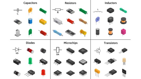
fig:google-electronics

fig:google-electronics
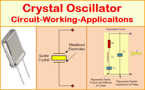
fig:Crystal-Oscillator
This list covers some of the basic electronic components, and there are many more specialized components used for specific applications within the field of electronics.
#electronic#electricity#electric vehicles#electric cars#engineering#semiconductors#wireless#cables#electronics#smartphone#hardware
3 notes
·
View notes
Text
Understanding the Role of Resistors and Semiconductors in Electronics
Electronic Components
In the realm of electronics, resistor and semiconductors are fundamental components that play crucial roles in the functioning of circuits. Whether you’re dealing with simple circuits or complex electronic systems, understanding these components is essential for anyone interested in electronics.
What is a Resistor?
A resistor is a passive electronic component that limits or regulates the flow of electric current in a circuit. Its primary function is to resist the current, hence the name "resistor." Resistors are used to control voltage levels, divide voltages, and limit the current that flows through a circuit, protecting other components from potential damage.
Types of Resistors
Resistors come in various types, each designed for specific applications:
Fixed Resistors: These have a set resistance value that doesn’t change.
Variable Resistors: Also known as potentiometers, these resistors can be adjusted to vary their resistance.
Thermistors: These are temperature-sensitive resistors, whose resistance changes with temperature.
Introduction to Semiconductors
Semiconductors are materials with electrical conductivity between that of a conductor and an insulator. They are the backbone of modern electronics, forming the basis for a wide range of devices, including diodes, transistors, and integrated circuits.
Properties of Semiconductors
Semiconductors, such as silicon and germanium, have unique properties that allow them to control electrical current in ways that are essential for modern electronics. Their conductivity can be altered by introducing impurities, a process known as doping, which increases their ability to conduct electricity.
The Relationship Between Resistors and Semiconductors
In electronic circuits, resistors and semiconductor often work together to achieve desired outcomes. For example, in a transistor—a semiconductor device—a resistor is often used to control the current flowing into the base of the transistor. This interaction allows the transistor to function effectively as an amplifier or a switch.
Resistors are also used in semiconductor circuits to stabilize voltage levels, ensuring that the semiconductors operate within their optimal range. Without resistors, semiconductors might not perform as intended, leading to circuit failures.
Practical Applications of Resistors and Semiconductors
Resistors and semiconductors are found in countless applications, from simple household devices to advanced computing systems. Resistors are used in power supplies, LED circuits, and as part of voltage dividers. Semiconductors, on the other hand, are the heart of microprocessors, memory chips, and sensors.
The combination of resistors and semiconductors allows engineers to design circuits that are both efficient and reliable, making them indispensable in the world of electronics.
Understanding resistors and semiconductors is crucial for anyone interested in electronics. These components work hand in hand to regulate and control the flow of electricity in circuits, making them foundational to modern technology.
Our website has a wealth of information on this subject.
inverter logic gate
radio frequency identification tags
0 notes
Text

Component description of PCBA patch processing
PCBA patch processing mainly includes two major processes: PCB circuit board production and SMT patch processing. Electronic components are indispensable in the process. Electronic components are the basic part of PCBA patch processing and an important factor affecting the performance and quality of PCBA finished products. So what are the commonly used electronic components for PCBA patch processing?
1. Resistor
Resistors are electronic components with resistance characteristics and are one of the most widely used components in PCBA processing. Resistors are divided into fixed resistors and variable resistors (potentiometers), which play the role of voltage division, current division and current limiting in the circuit.
2. Capacitors
Capacitors are also one of the basic components in PCBA processing. They are components that store electrical energy and play the role of coupling, filtering, DC isolation and tuning in electronic circuits.
3. Inductor coils
Inductor coils are referred to as inductors and have the function of storing magnetic energy. Inductor coils are usually composed of skeletons, windings, shielding covers, magnetic cores, etc.
4. Potentiometers
Resistors with variable resistance values, that is, resistors that can be continuously adjusted within a specified range, are called potentiometers. The potentiometer consists of a housing, a sliding end, a rotating shaft, a ring resistor and three lead-out terminals.
5. Transformer
The transformer consists of an iron core (or magnetic core) and a coil. The coil has two or more windings, of which the winding connected to the power supply is called the primary coil, and the remaining windings are called the secondary coil.
The transformer is a device that converts voltage, current and impedance. When an AC current flows through the primary coil, an AC magnetic flux is generated in the iron core (or magnetic core), causing a voltage (or current) to be induced in the secondary coil. The transformer is mainly used for AC voltage conversion, current conversion, power transmission, impedance conversion and buffer isolation, etc. It is one of the indispensable important components in the PCBA machine.
6. Crystal diode
The crystal diode (i.e. semiconductor diode, hereinafter referred to as diode) is made of a PN junction, electrode leads and an external sealed tube shell, and it has a unidirectional conductive characteristic.
7. Crystal triode
The crystal triode (hereinafter referred to as triode) is the core device for signal amplification and processing, and is widely used in PCBA machines.
8. Field Effect Transistor
Field effect transistor (FET for short) is also a semiconductor device with PN junction. Unlike triode, it does not use the conductive property of PN junction, but its insulating property.
9. Electroacoustic Device
The device used to complete the conversion between electrical signal and sound signal in the circuit is called electroacoustic device. There are many types of it, including speakers, microphones, headphones (or earplugs), transmitters, receivers, etc.
10. Photoelectric Device
Photoconductive devices that work with the photosensitive properties of semiconductors, photovoltaic cells and semiconductor light-emitting devices that work with semiconductor photovoltaics are collectively referred to as photoelectric devices.
11. Display Device
Electronic display device refers to a photoelectric conversion device that converts electrical signals into optical signals, that is, a device used to display numbers, symbols, text or images. It is a key component of electronic display devices and has a great impact on the performance of display devices.
12. Sensor
The sensor can sense the specified measured value and convert it into a usable signal according to a certain rule. It is usually composed of a sensitive element and a conversion element.
13. Surface Mount Components
Surface mount components (SMC and SMD) are also called patch components or chip components. They include resistors, capacitors, inductors and semiconductor devices, etc. They have the characteristics of small size, light weight, no leads or very short leads, high installation density, high reliability, good vibration resistance, and easy automation.
14. Thyristor
SCR, short for silicon-controlled rectifier, is a high-power semiconductor device with a four-layer structure of three PN junctions, also known as thyristor. It has the characteristics of small size, relatively simple structure and strong functions, and is one of the more commonly used semiconductor devices.
15. Switches, relays, and various connectors
Switches are used to cut off, connect or convert circuits in electronic equipment. Relays are automatic control devices that will change the output in a jumpy manner when the input quantity (electricity, magnetism, sound, light, heat) reaches a certain value.
If you have interest in our service, please feel freely contact Cynthia at [email protected] & 86 18126197150.
0 notes
Text
PWM LED dimmer

Let's build a fully analog PWM LED dimmer on four operational amplifiers and learn what PWM is used for and what it actually is.
As most of us already know, the brightness of the LED depends on the current flowing through it, while the voltage on the LED stays nearly the same when the current changes.
To set the current, in the simplest case with a constant supply voltage, one includes a resistor in series with the LED.

Then, the voltage of the power supply will be equal to the sum of the operating voltage of the LED, which can be considered constant, and the voltage drops across the resistor.
According to Ohm's law, the voltage drop across a resistor is its resistance times the current.
According to the Joule-Lenz law, the DC power equals the voltage times the current.
Suppose we have a powerful white LED with an operating voltage of 3 volts and an operating current of 1 ampere. And we power it from a source with a voltage of 4 volts.
In this case, at a current of 1 A, we have a 1-ohm resistor. It drops 1 volt and generates 1 watt of heat. This is quite high power; a high-power resistor would be needed.
The LED gets 3 watts out of a total power consumption of 4 watts. The efficiency of such a flashlight is 3/4 = 75%, not considering the energy lost to heat the LED or the internal resistance of the battery.
If one takes a 2-ohm resistor, the voltage drop across it will remain at 1 volt because 4 volts of power supply minus 3 volts for the LED equals 1 volt.

The current, in this case, will be 0.5 amperes, the power consumption of the LED will be 1.5 watts, and the losses on the resistor will be 0.5 watts.
The efficiency remains the same. It is equal to the ratio of the operating voltage of the LED to the supply voltage.
To adjust the LED current, one can use a potentiometer. But a variable resistor with a power rating of 1 watt is quite a rare thing. To change the brightness of the LED with a low-power potentiometer, we can use a transistor-based current source.
Let's hook up a high-power transistor into the circuit with a common collector called an emitter repeater. The voltage across the current-limiting shunt will equal the voltage across the base minus the Ube of the transistor.

The voltage Ube between the base and emitter can be considered a constant value. It can be in the range of 0.6 to 0.8 volts, and basically, it can be equated to the forward voltage drop across a silicon diode. After all, the two P-N junctions of the transistor are essentially diodes.
Considering the Ube of the transistor Q1 is equal to the forward drop on the diode D2 and equal to 0.65 volts, the voltage across the series-connected R2 and RV1 will be 4 minus 0.65 = 3.35 volts. The current, through their total resistance of 335 ohms, will equal 10 milliamperes.
Let's say that the current gain of our transistor is greater than 400. Then, at a collector current of 1A, the base current will be less than 2.5 milliamps. For the sake of simplicity, we'll neglect this current. However, it is a quarter of 10 mA current through potentiometer RV1 and limiting resistor R2.
Because we have compensated Ube by the drop across diode D2, the emitter follower works so that the voltage across shunt R1 will equal the voltage between anode D2 and brush RV1.
In the lowest position of RV1 in the diagram, the voltage across the shunt and, consequently, the emitter current of the transistor and the LED current will be zero.
In the top-most position, the voltage will be 3350 × 15 / (320 + 15) = 150 millivolts. In this case, the current through R1 with a resistance of 150 milliohms will equal 1 ampere. So, we got ourselves a smooth adjustment of the LED brightness with a low-power potentiometer and a powerful transistor.
The heat generation of RV1 will be 150 mV × 10 mA = 1.5 milliwatts.
If we consider the base current of the transistor equal to 2.5 mA, then R2 should have a voltage drop of 3.2 V at a current of 12.5 mA instead of 10 mA. This means the resistance of R2 should be 3200 / 12.5 = 256 ohms.
The scheme I have drawn up is good for illustration purposes rather than practical application. There is too much instability and dependence on the parameters of specific components.
There is a probability that the LED current will exceed its rating of 1 ampere and burn out. Or vice versa, the current and, therefore, the brightness will be too low. And we have not accounted for the fact that as the battery discharges, its voltage drops, especially under load.
In the past, electronic DIY devices and even mass-manufactured ones had to be tuned by hand-picking compatible components before packaging them for sale, just like this circuit. That's because electronic components were expensive, inaccurate, and unstable.
Today, components are much more advanced and affordable, and they can be used to create a circuit that is stable and doesn't require meddling.
To eliminate the need to consider the base-emitter voltage of the transistor, let's use an operational amplifier.
An ideal operational amplifier is described by two statements. First, its input impedance is huge, and virtually no current flows through its inputs.
Second, an operational amplifier will set the output voltage such that the voltages at the inverting and non-inverting inputs are equal. (Through a feedback loop from the output to the inverting input.)
Here, the operational amplifier is connected as a voltage follower. And it is not an emitter follower but a full-fledged follower. The voltage on the shunt R1 will go to the inverting input and is thus almost precisely (with a difference of no more than 3 millivolts, most often about 300 microvolts) equal to the voltage on the non-inverting input, which is set by the knob of the potentiometer RV1.

The precision voltage reference TL431 is used to stabilize the voltage on the potentiometer. The voltage at the cathode U2, and consequently at the divider R3 RV1, is 2.5 volts. Of this, the potentiometer gets 1/25 = 100 millivolts.
That means we can adjust the voltage at the 100 milliohm shunt R1 from 0 to 100 millivolts, and thus the current from 0 to 1 amp.
Congratulations! We have built an LED brightness regulator with a stabilized current that does not depend on the supply voltage, i.e., the battery charge percentage.
The efficiency of the transistor regulator is still the ratio of the LED operating voltage to the supply voltage. In this case, the same 75%, minus tiny losses to power auxiliary circuits.
At maximum operating current on the current limiting resistor (shunt), it dissipates just 0.1 watts of heat. In contrast, on the transistor (which is easy to equip with a heat sink), it dissipates the remaining 0.9 watts.
If only we had a current stabilizer with a pulse energy converter, as in the post about a boost LED driver, we could significantly increase the efficiency!
The pulse stabilizer's shunt resistance can be even more minor—tens or even single milliohms. The resistance of the MOSFET in an open state can be the same.
On the other hand, other energy losses characteristic of pulse converters are added, mainly for remagnetizing the core of the inductor coil and for the ESR of the output electrolytic capacitor. So we need a good coil and a good cap.
Pulse width modulation, which is also used in switching power supplies, does not regulate the current amplitude. Instead, it interrupts the current several hundred, thousand, or more times per second.

By interrupting the current, electrical charge and power are reduced compared to the always-on state. At the same time, the transistor is operating in key mode, so the voltage drops across, and the heat losses are minimal.
This is one of many advantages of PWM over linear control. The microcontroller needs a digital-to-analog converter (DAC) to output the control voltage. And it is much easier for the microcontroller to output the time intervals that define the on and off states and to generate pulses to turn on the transistor.
When adjusting the brightness of LEDs, PWM may have a disadvantage: flickering can be heavy on the eyes, cause fatigue, and, in industrial environments, even lead to fatal accidents.
This can happen due to the stroboscopic effect; rotating machinery parts may appear slower, stationary, or spinning in the opposite direction. Together with flicker fatigue, this can create a dangerous premise.
Therefore, the questions of the overall quality of LED lighting, its energy and cost efficiency, and the extension of the service life of LEDs remain open.
PWM is most often implemented on special analog IC controllers as well as on microcontrollers using digital counters and timers. And today, we will look closely at and test a classic circuit on three operational amplifiers (plus one buffer).

A relaxation oscillator, or multivibrator, is assembled on U1A and U1B. Its feature is that the timing capacitor C1 is included in the negative feedback loop of the operational amplifier U1B. Because of this, the voltage at the output of U1B varies linearly, and we have an almost perfect triangular waveform.

U1A is used as a comparator with hysteresis (a positive feedback loop through resistor R9). The voltage at the inverting input is always zero because it is connected to the circuit ground. (Note that the power supply is bipolar: +12 and -12 volts.) This is uncommon for real LED dimmers, but a board we have is for educational experiments.
When a positive voltage appears at the non-inverting input U1A, the comparator output switches to the high logic level state (plus supply minus the voltage drop across the chip's output transistors).
Conversely, when the voltage at the non-inverting input U1A becomes negative, the comparator switches to a low logic level state.
Resistor R8 and two counter-sequential Zener diodes, D1 and D2, form a simple parametric voltage-limiting stabilizer. It is +6 volts at the high level and -6 volts at the low level.

This is how rectangular pulses of a given amplitude with a frequency of 859 hertz and a duty cycle of exactly 50% are obtained because the circuit is symmetrical: the time-delay capacitor is charged and then discharged through the same circuit, and the absolute value of the positive voltage is equal to the absolute value of the negative voltage.
Accordingly, the triangular waveform is also wholly symmetrical. The oscilloscope shows a fill factor of 50%.
U2A is used simply as a voltage repeater buffer, and strictly speaking, it is optional because operational amplifiers have a high input impedance.

U2B is a PWM comparator. It will switch high when the instantaneous value of the triangular waveform voltage from U1B is lower than the voltage set by potentiometer RV1. In this way, the potentiometer adjusts the fill factor.

Note that when the duty cycle is low, the voltage at the output of U2B does not reach its maximum. This is because the edges of the pulses are not exactly vertical. The output voltage rises, and falls are not instant. An operational amplifier has a slew rate parameter, and the LM358 has a rather low one.

Next, a push-pull amplifier with three transistors is connected, and the signal from its output controls the stage on transistor Q4, which interrupts the LED current. In the video, we can see how it all works.
youtube
Thanks for your attention!
0 notes
Text
Nichrome Wire: Properties, Applications, and Benefits
What is Nichrome Wire?
Nichrome wire, an alloy composed primarily of nickel and chromium, is known for its high electrical resistance and excellent heat resistance. Typically, the composition ranges from 60-80% nickel and 20-40% chromium, making it highly durable and resistant to oxidation at high temperatures.
Properties of Nichrome Wire
1. High Melting Point: Nichrome wire can withstand temperatures up to 1200°C (2192°F), making it ideal for high-temperature applications.
2. Electrical Resistance: It offers a consistent resistance over a wide temperature range, making it reliable for various electrical applications.
3. Corrosion Resistance: The chromium content provides excellent resistance to oxidation and corrosion, even at elevated temperatures.
4. Ductility: Nichrome wire is highly ductile, allowing it to be drawn into thin wires and formed into various shapes without breaking.
5. Stability: It maintains its integrity and performance under extreme thermal cycling conditions, making it a preferred material in many industrial processes.
Applications of Nichrome Wire
1. Heating Elements:
- Industrial Furnaces: Used in heating elements for furnaces due to its high melting point and stability.
- Household Appliances: Commonly found in toasters, hairdryers, and electric ovens.
- Laboratory Equipment: Used in heating coils and other devices requiring precise temperature control.
2. Resistors:
- Precision Resistors: Used in precision resistor manufacturing due to its consistent resistance properties.
- Variable Resistors: Employed in rheostats and potentiometers for variable resistance applications.
3. Thermocouples:
- Temperature Measurement: Paired with other metals to form thermocouples for accurate temperature measurement in various industrial processes.
4. Cutting Tools:
- Foam and Plastic Cutting: Used in hot wire foam cutters and plastic cutting tools due to its ability to maintain a constant temperature. Although initially more expensive than some other materials, its longevity and performance make it a cost-effective choice in the long run.
Conclusion
Nichrome wire, with its unique properties and wide range of applications, is an essential material in various industries. Whether for industrial heating elements, precision resistors, or creative projects, nichrome wire offers reliability, durability, and versatility, making it a valuable component in modern technology and manufacturing processes.
#cable manufacturers in florida#wire manufacturers in florida#industrial wire#wires#cables#wire manufacturers#cable manufacturers
0 notes
Text
What are the Applications and Limitations of Wheatstone Bridge?
In order to find an unknown resistance in a circuit, the Wheatstone bridge is actively used. And it is very important to solve various types of problems and questions that involve resistors, and other circuits. So, it is very important for the students to understand the working of Wheatstone Bridge. And therefore, to help you out, here in the article below, we will provide a comprehensive description of Wheatstone Bridge.
Principle of Wheatstone Bridge
The Basic Principle of Wheatstone Bridge is the Principle of Null Deflection. According to this principle, there is no current present in this circuit, and the ratio of resistances is said to be the same. Moreover, at first, the bridge in the circuit, as shown in the diagram, exists in an unbalanced condition, and they can find the current is indeed flowing through the galvanometer. However, in order to keep the bridge in a balanced condition, there should not be any current flow in the circuit. Although to achieve this balanced position, it is needed to adjust the variable resistance and known resistance in the circuit.
Applications of Wheatstone Bridge
In order to measure the low resistance in a circuit.
Other important quantities such as Capacitance, Impedance, and Inductance, can also be calculated using Wheatstone Bridge.
By using an optional amplifier, in the Wheatstone bridge, we will be able to measure physical parameters like Strain, Light, and Temperature.
Limitations of Wheatstone Bridge
There are certain limitations to all types of principles in Physics, including the Wheatstone Bridge.
Excessive current flow in the Wheatstone Bridge may result in a permanent change in the value of resistance.
When low resistance is applied, leads and contacts in the circuit will cause an error, and their values will attain constant.
And in terms of high resistance, the measured values are off-charts, then the galvanometer is considered to be in imbalance.
The basic Wheatstone Bridge consists of four resistive arms forming a diamond shape with a voltage source connected across one diagonal and a galvanometer connected across the other diagonal. The bridge is typically balanced when the ratio of the resistances in one pair of arms equals the ratio in the other pair.
Here's how it works:
Balancing Principle: When the bridge is balanced, no current flows through the galvanometer. This occurs when the ratio of resistances in one pair of arms is equal to the ratio in the other pair. Mathematically, this condition can be expressed as
Measurement: By varying one of the resistances in the bridge (often done with a variable resistor or potentiometer), the bridge can be unbalanced. The amount of unbalance can be measured by the deflection of the galvanometer. This deflection is directly proportional to the unknown resistance being measured.
Applications: Wheatstone Bridges are extensively used in various fields. For instance, in strain gauge applications, a strain gauge is connected to one of the resistive arms. When subjected to mechanical stress, the strain gauge's resistance changes, causing an imbalance in the bridge. By measuring this imbalance, one can determine the strain on the object to which the gauge is attached.
Temperature Compensation: Wheatstone Bridges are also employed in temperature sensors. Thermistors or resistance temperature detectors (RTDs) are used as the variable resistors. Changes in temperature alter the resistance of these devices, leading to an imbalance in the bridge. By measuring this imbalance, precise temperature readings can be obtained.
Advantages: Wheatstone Bridges offer high accuracy and sensitivity, making them invaluable in precision measurements. They can measure small changes in resistance with great precision, making them suitable for a wide range of applications requiring accurate measurements.
There are many other complex topics and chapters in Physics subject, which might need the students to put in some extra hard work to understand them easily and thoroughly. However, instead of self-study, we suggest students join online interactive classes. And if you are looking for a cost-effective online coaching program, with amazing benefits, then go check out the online interactive class programs offered by the Tutoroot platform.
0 notes
Text
Everything You Need to Know About Digikey Resistors - Technology Org
New Post has been published on https://thedigitalinsider.com/everything-you-need-to-know-about-digikey-resistors-technology-org/
Everything You Need to Know About Digikey Resistors - Technology Org
You’re probably aware that Digi-Key Electronics is a global electronic components distributor known for its wide selection of parts, including an extensive range of resistors.
Two resistors on a PCB. Image credit: gosiak1980 via Pixabay, free license
The truth is that resistors are fundamental components in virtually every electronic circuit, tasked with regulating current flow, dividing voltages, and performing a multitude of other essential functions. Discover more info here https://spectrum.ieee.org/slideshow-a-day-in-the-life-of-digikey.
So, understanding the different types of resistors and their specific applications is crucial for engineers, hobbyists, and professionals working in the electronics field. Digi-Key’s inventory covers a broad spectrum of resistor types, including fixed resistors, variable resistors, resistor networks, and special-purpose resistors, catering to a wide variety of electronic applications.
Fixed Resistors
Three resistors in a breadboard setup. Image credit: Harrison Broadbent via Unsplash, free license
Firstly, you should know that fixed resistors are the most common type found in electronic devices. These components have a predetermined resistance value that does not change over time or due to environmental conditions. Digi-Key offers fixed resistors in various form factors, including through-hole, surface mount, and chassis mount options, with resistance values ranging from fractions of an ohm to several megaohms.
Materials used in fixed resistors can vary, leading to differences in performance characteristics such as tolerance, temperature coefficient, and power rating. When selecting a fixed resistor from Digi-Key, consider the application’s voltage and current requirements to ensure the resistor can handle the expected power dissipation without exceeding its maximum ratings. Learn more on this page.
Variable Resistors
Variable resistors, or potentiometers, allow for the adjustment of resistance values within a specific range. These components are crucial for applications requiring fine-tuning of circuit parameters, such as volume controls in audio equipment or sensitivity adjustments in sensors.
Digi-Key’s selection includes both rotary and slide potentiometers, trimmers for circuit board mounting, and rheostats for handling higher power applications. When choosing a variable resistor, it’s important to consider the total resistance, adjustment range, physical size, and power rating to ensure compatibility with the intended application.
Resistor Networks
Resistor networks, also known as resistor arrays, consist of multiple resistors integrated into a single package. These components are ideal for use in applications requiring matched resistor values, such as voltage dividers or digital-to-analog converters.
Digi-Key provides resistor networks in various configurations, including isolated, bussed, and dual-terminator types, to accommodate different circuit designs. Resistor networks help streamline circuit layouts, reduce board space, and simplify assembly processes, making them a practical choice for densely packed electronic devices.
Meeting Unique Needs
Beyond standard resistive components, Digi-Key also offers special-purpose resistors designed for specific applications. This category includes current sense digikey resistors for precise current measurement, thermistors for temperature sensing, and varistors for transient voltage suppression.
Each type of special-purpose resistor has unique characteristics tailored to its specific function, such as low resistance values for minimal power loss in current sense resistors or negative temperature coefficients for thermistors. When selecting these components, understanding the application’s specific requirements is critical to ensure optimal performance and reliability.
Tips for Finding the Right Resistor
Navigating Digi-Key’s expansive inventory to find the perfect resistor for your project can be a breeze with the right approach. Given the critical role that resistors play in electronic circuits, choosing the right one is paramount to the success of any project.
Here are some tips to help you efficiently sift through Digi-Key’s selection and pinpoint the resistor that best fits your needs:
Define Your Requirements Clearly
Before diving into Digi-Key’s inventory, have a clear understanding of your project’s specific requirements.
This includes knowing the resistance value, power rating, tolerance, and temperature coefficient needed for your application. Consider the environment in which the resistor will operate, such as high-temperature conditions or exposure to high levels of moisture, as these factors can influence the type of resistor best suited for your project.
Use the Advanced Search and Filtering Tools
Digi-Key’s website is equipped with sophisticated search functionalities that allow you to narrow down your options based on various parameters.
Once you’ve defined your requirements, utilize these tools to filter results by resistance value, tolerance, power rating, and other relevant specifications. This can significantly reduce the time spent searching for the right component among thousands of options.
#analog#applications#approach#Arrays#audio#board#change#devices#diving#electronic#electronic devices#Electronics#engineers#Environment#Environmental#equipment#filter#form#Fundamental#Global#Hardware & gadgets#IEEE#it#Learn#life#materials#moisture#networks#One#Other
0 notes
Text
Makerspaces Week 3
We have made it through yet another 168 hours of Makerspaces! This week was full of opportunities to test yourself and grow as a creator.
This week's circuits showed me the light- both mentally and quite literally. Last week's circuit was rough but with some continued practice, this week's circuits, although more tedious, went very well. We had 2 builds this week, Circuit #3 which is the color changing LED circuit, and Circuit #4 which is the multi LED circuit. The coding for the builds revealed their actualities and what leads to their successful functions. Once the boards were constructed, coded, and tested, the next challenge was to combine the codes and run them simultaneously.
Circuit #3
Circuit 3- Color changing LED
The basis of this circuit is the LED prongs. Each one represents a primary color- red, green, and blue, with a ground prong in between (it is the longest prong)
You can make a magnitude of colors with these
The different colors come from the variation/ cycling of power supply to the specific LED prongs
Resistors are in the circuit to control how much power accesses the prongs each, making sure they are not fried
Display time see to 100 ms
I can use this to adjust the fade time- faster or slower
Cycles through 8 colors- i can make more by adjusting the power supply between the 3 pin colors in the code- HIGH, LOW
Red: R- High, G- Low, B- Low
Green: R- Low, G- High, B- Low
Blue: R- Low, G- Low, B- High
Yellow: R- High, G- High, B- Low
Etc
1000 ms delay between each
See video below for circuit 3
Circuit 4- Multiple LEDs
The basis of this circuit was to explore the new concept of Arrays- holding multiple variables.
Each LED has its on pin and the pin locations are important because they have to correlate in the code
Arrays are important in coding because they represent certain variables. They start at an index of 0
In the code you have to notate the series of pins being used. I chose the code where all of the lights are turned on, and then all back off
1000ms time delay
See video below for circuit 4
Compound build-
I used components from the last few circuit builds
Multiple LEDS
Color changing LED
Potentiometer
Combined code: modified the pin locations because i only used 3 LEDs for that section
Programed the color changing LED to only show main colors- put that location in the same code as the multi LEDs and used the color LED in place of 3 additional
Programmed and connected the potentiometer. I tested it with one location and modified the code to say pin 2 instead of the basic pin 13. It worked and I was able to change the speed
I tested each of the codes separately and they all work
For the combination circuit, the goal was to have a “countdown” to the color changing LED. I would also be able to control the speed with the potentiometer
I used 3 regular LEDs, 1 multicolor LED, and 1 potentiometer
I tried to combine the codes to run all of the functions at the same time but it kept receiving error messages
See video below for compound build
The Codes I used for each of my programs:
Multi LED
int ledPins[] = {2,3,4,5,6,7};
void setup()
{
int index;
for(index = 0; index <= 5; index++)
{
pinMode(ledPins[index],OUTPUT);
// ledPins[index] is replaced by the value in the array.
// For example, ledPins[0] is 2
}
}
void loop()
{
void oneAfterAnotherNoLoop()
{
int delayTime = 100;
// turn all the LEDs on:
digitalWrite(ledPins[0], HIGH); //Turns on LED #0 (pin 2)
delay(delayTime); //wait delayTime milliseconds
digitalWrite(ledPins[1], HIGH); //Turns on LED #1 (pin 3)
delay(delayTime); //wait delayTime milliseconds
digitalWrite(ledPins[2], HIGH); //Turns on LED #2 (pin 4)
delay(delayTime); //wait delayTime milliseconds
digitalWrite(ledPins[3], HIGH); //Turns on LED #3 (pin 5)
delay(delayTime); //wait delayTime milliseconds
digitalWrite(ledPins[4], HIGH); //Turns on LED #4 (pin 6)
delay(delayTime); //wait delayTime milliseconds
digitalWrite(ledPins[5], HIGH); //Turns on LED #5 (pin 7)
delay(delayTime); //wait delayTime milliseconds
// turn all the LEDs off:
digitalWrite(ledPins[5], LOW); //Turn off LED #5 (pin 7)
delay(delayTime); //wait delayTime milliseconds
digitalWrite(ledPins[4], LOW); //Turn off LED #4 (pin 6)
delay(delayTime); //wait delayTime milliseconds
digitalWrite(ledPins[3], LOW); //Turn off LED #3 (pin 5)
delay(delayTime); //wait delayTime milliseconds
digitalWrite(ledPins[2], LOW); //Turn off LED #2 (pin 4)
delay(delayTime); //wait delayTime milliseconds
digitalWrite(ledPins[1], LOW); //Turn off LED #1 (pin 3)
delay(delayTime); //wait delayTime milliseconds
digitalWrite(ledPins[0], LOW); //Turn off LED #0 (pin 2)
delay(delayTime); //wait delayTime milliseconds
}
Potentiometer
int sensorPin = 0;
int ledPin = 2;
void setup() //
pinMode(ledPin, OUTPUT);
void loop(){
int sensorValue;
sensorValue = analogRead(sensorPin);
digitalWrite(ledPin, HIGH); // Turn the LED on
delay(sensorValue); // Pause for sensorValue
// milliseconds
digitalWrite(ledPin, LOW); // Turn the LED off
delay(sensorValue); // Pause for sensorValue
// milliseconds
// Remember that loop() repeats forever, so we'll do all this
// again and again.
}
Final reflection looking at what you learned through the project, the process you took to make it work or if it is not working, what the next steps would be to further debug the project.
Throughout this project, I’ve learned that you can combine multiple codes into one file, making the device have multiple functions. I also noted that just because a circuit can work electrically, does not mean it will work code wise. Also, it is very easy to create a code to run individually, but it becomes a challenge when you are trying to combine them into one code file. My next steps are to get better at coding different codes in one file. I believe I am steady enough to build the circuits quite easily. I’ve been able to sketch a vision and execute it physically, I just need to fine tune my code writing.
Finally, look at the project you completed and share possible extensions of this project into where you may find examples of similar programs/circuits in the real world.
Some real work applications using some of the builds from this week include LED screens, the individual lights will light based on what the user wants the board to say and the position of the LEDs. Other examples include Christmas lights and lights inside of a home that have the dimmer capability. I would like to explore the dimming portion on the potentiometer.
0 notes
Text
3296W-1-501LF
The 3296W-1-501LF trimmer potentiometer is a variable resistor commonly utilized in electronic circuits. This potentiometer is a single-turn wirewound device with a resistance range of 500 ohms and a maximum power rating of 0.5W.
The 3296W-1-501LF is designed to be adjustable with a slot-style adjustment mechanism that can be used to set its resistance value to a specific value. This potentiometer is highly stable, ensuring that the resistance value remains consistent over time. It is also durable, constructed with high-quality materials and comes with a dustproof cover to protect it from damage and debris.
The compact size of this trimmer potentiometer makes it an ideal choice for use in small electronic devices with space constraints. Its high stability and reliability make it suitable for use in a range of applications, including audio equipment, communication devices, and industrial machinery.
In conclusion, the 3296W-1-501LF trimmer potentiometer is a reliable component that can be used to adjust or control voltage or current in electronic circuits. Its high stability, durability, and compact design make it an excellent choice for a range of applications.

0 notes
Text
Empowering Electronics: The Rise of Resistors Manufacturers in India
Introduction
In today's digitally-driven world, electronics are an integral part of our daily lives, from smartphones to laptops, and even the appliances in our homes. Behind every electronic device lies a complex web of components that make it function seamlessly. One such component that plays a crucial role in electronic circuits is the resistor. In India, the resistor manufacturing industry has witnessed significant growth in recent years. In this article, we will delve into the world of resistors and explore the reasons behind the rise of resistor manufacturers in India.
The Basics of Resistors
Before we dive into the manufacturing landscape, let's understand the basics of resistors. Resistors are passive electronic components that limit the flow of electric current in a circuit. They are used to control voltage levels, manage current, divide voltages, and protect sensitive components from excessive currents. Resistors come in various types, including fixed resistors, variable resistors (potentiometers), surface mount resistors, and more. These components are vital in the design and functionality of electronic devices.
The Growth of the Resistors Manufacturing Industry in India
Technological Advancements: India has witnessed significant technological advancements in recent years. With a skilled workforce and access to advanced manufacturing technologies, Indian companies have the capability to produce high-quality resistors that meet global standards. This technological progress has played a pivotal role in the growth of the resistor manufacturing industry in India.
Increasing Demand: The demand for electronic devices has been steadily rising, not only in India but also globally. As more and more devices are manufactured and assembled in India, there is a corresponding increase in the demand for electronic components, including resistors. This surge in demand has encouraged the growth of domestic resistor manufacturing companies.
Government Initiatives: The Indian government has been actively promoting the electronics manufacturing sector through initiatives like "Make in India" and "Digital India." These programs aim to boost domestic production and reduce reliance on imports. Incentives and subsidies provided to electronics manufacturers have attracted investments in the resistor manufacturing sector.
Quality Standards: Indian resistor manufacturers have focused on maintaining international quality standards to cater to both domestic and export markets. This commitment to quality has helped them establish a strong presence in the global resistor market.
Cost-Effective Manufacturing: India offers cost-effective manufacturing solutions, including competitive labor costs and access to raw materials. This cost advantage has made India an attractive destination for resistor manufacturing.
Conclusion:-
The growth of resistor manufacturers in India is a testament to the country's capability to compete on a global scale in the electronics manufacturing industry. With a strong focus on technology, quality, and cost-effective production, Indian resistor manufacturers are poised to play a crucial role in meeting the increasing demand for electronic components in India and beyond. As the world continues to rely on electronic devices, the resistor manufacturing industry in India is set to thrive and contribute significantly to the country's economic growth.
For more info:-
power resistor manufacturer
High Power Wire Grid Resistors
Edge Wound Resistor Supplier from India
aluminium housed resistors
Aluminium housed Resistor Manufacturers in India
Source URL:-https://sites.google.com/view/resistors-manufacturer-india/home
0 notes
Text
Excellent growth of Digital Potentiometer IC Market- Comprehensive study by key players: Analog Device, Texas Instruments, Microchip, Ams, ON Semiconductor, etc
The digital potentiometer IC market refers to the market for integrated circuits (ICs) that are designed to function as digital potentiometers. A digital potentiometer is an electronic component that mimics the behavior of a traditional mechanical potentiometer (variable resistor) but can be controlled digitally. It is commonly used in various electronic systems and applications where precise and automated adjustment of resistance is required.
Digital potentiometer ICs are typically used in audio systems, instrumentation, telecommunications equipment, automotive electronics, and other electronic devices. They offer advantages such as improved reliability, smaller size, lower cost, and the ability to integrate multiple potentiometers into a single IC package. They can be controlled using digital signals, such as I2C or SPI, allowing for easy interfacing with microcontrollers and other digital devices.
Click Here By - https://www.marketinforeports.com/
The market for digital potentiometer ICs has been growing steadily in recent years due to the increasing demand for electronic devices with digital control capabilities. The rise of smart homes, IoT devices, and wearable electronics has also contributed to the market growth. Additionally, advancements in semiconductor technology have enabled the development of digital potentiometer ICs with improved performance, such as higher resolution, lower power consumption, and faster response times.
Key players in the digital potentiometer IC market include major semiconductor manufacturers such as Texas Instruments, Analog Devices, Maxim Integrated, Microchip Technology, and ON Semiconductor, among others. These companies offer a wide range of digital potentiometer ICs with varying specifications and features to cater to different application requirements.
Factors driving the growth of the digital potentiometer IC market include the increasing adoption of digital control technologies, the need for smaller and more efficient electronic systems, and the expanding consumer electronics industry. However, the market also faces challenges such as intense competition, price pressures, and the availability of alternative technologies.
Overall, the digital potentiometer IC market is expected to continue its growth trajectory in the coming years, driven by technological advancements and the expanding applications of digital control in various industries.
0 notes
Text
Potentiometers Supplier|Variable Resistors Supplier
Get precise control with industrial automation potentiometers and variable resistors at Auto2mation.com. Free Delivery and moneyback guarantee.
0 notes
Text
The new life for your old AM radio (DIY micro power AM MW transmitter AMT-MW207)

Are you the type of person who likes listening to good ol' radio like I do? Unfortunately, medium-wave broadcasting has decayed in the last few decades. There's nothing in many areas, even at night when medium wavelengths work best. That’s why the radios from our childhood stay unused and collect dust.
Today, we will make a small medium-wave radio transmitter that can help you check and configure AM radio receivers and listen to music through them if you connect an MP3 player or smartphone.
The power of this transmitter is 0.0005 watts, and the range is about 3 feet, so you won't disturb your neighbors or need a license for it.
The transmitter is AMT-MW207 and was developed by an enthusiast under the nickname "Radio Lover". The circuit is proven to work perfectly and stays unchanged, but the layout of the PCBs can be different. For example, here is the newest and perhaps most nice-looking version 1.3 revision 2, dated September 15, 2022.
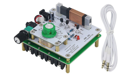
I've assembled ver. 1.2 rev. 7. It has a green board, no frequency scale, and the wavelength adjustment knob is located at the very bottom of the board. I consider these differences to be purely aesthetic. The transmission frequency can be viewed much more accurately on the screen of a separate frequency meter or oscilloscope.
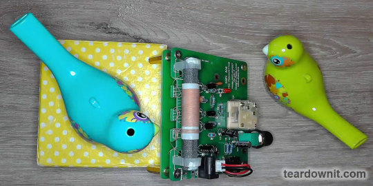
Older versions are less convenient to attach the testing hook of the oscilloscope to, and they have no cutouts in the back of the PCB for winding up excess wire. The differences are generally insignificant; all versions of the transmitter work and sound the same.
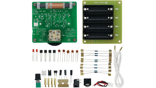
The DIY kit was designed and kitted with passion: brass fittings, high-quality AA battery holders, and neat resistor value markings.
The potentiometer volume knob was not forgotten either; they also got me a good 3.5 mm TRS-TRS cable. In fact, this is an important detail. You sure can twist the variable resistor's shaft without a handle. Still, you won’t be able to connect a player or a laptop if there is no connecting cable. You won’t be able to try out a freshly assembled device, which will ruin the mood.
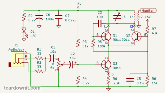
The transmitter circuit is simple yet elegant. Transistors Q1 and Q2 are a long-tailed pair, and Q3 is its current stabilizer.
A transistor current stabilizer is an emitter follower whose load is a resistor R6.
According to Ohm's law, the current through this resistor will be equal to the voltage across it divided by its resistance. The voltage at the emitter of a transistor connected to a circuit with a common collector is similar to the voltage at the base minus Vbe.
Vbe, the voltage between the base and the emitter for a particular transistor, is an almost constant value. Nothing is ideal, so Vbe actually depends on the temperature and base current, but these influences are tiny and can be ignored.
R3 and R4 together are a voltage divider. With a supply voltage of 6 volts, the current through this divider is 6V / (R3 + R4) = 6V / 59.2 kOhm = 101 µA. We neglect the base current of transistor Q3, which is connected in parallel with R4. I will explain why later.
The voltage at R4 is 101 µA * 8.2 kOhm = 828 mV. As Vbe = 0.63 V, resistor R6 gets the remaining 199 mV. Then, the current through it will be 60.3 µA.
The emitter current of transistor Q3 is the sum of its collector and base currents. The collector current is β times the base current, where β is the current gain coefficient of the transistor.
The average value of β for the 9011 transistor is 90. That is, the collector current is 60.3 µA * (β-1)/β = 60.3 µA * 89/90 = 59.63 µA.
The base current is 60.3 µA / β = 0.67 µA, less than 0.7% of the R3R4 divider current. Therefore, the base current can be neglected even in such a microampere case due to the fact that Q3 is connected as an emitter follower.
That is, it has a very high input impedance. It can even be calculated: Rin = Vin / Ib = 199 mV / 0.67 µA = 297 kOhm.
Even if our transistor has twice the current gain, β = 180, then the input resistance of such a stage with a common collector at an emitter current of 60 μA is twice as high and equals 594 kOhm.
So, the base current of Q3 is almost zero, and the collector current is almost equal to the emitter. The emitter follower has a high input impedance and can also serve as a voltage-to-current converter and a stable current generator.
This can be useful in many cases, for example, when powering LEDs. Or for generators of linearly varying voltage, their capacitors are charged with a stabilized current. Hence, the voltage across them increases linearly. In the era of cathode-ray oscilloscopes, such generators were used to deflect the beam horizontally.
In addition to the constant voltage from the divider R3R4, an audio signal is supplied to the base of transistor Q3. Identical resistors R1 and R2 mix stereo down to mono. Capacitors C1 and C2 let alternating current pass through and block direct current.
Potentiometer W regulates the amplitude of the signal. With the same voltage divider as R3R4, only the ratio of the resistances of the upper and lower branches can be changed by turning the knob.
So, transistors Q1 and Q2 form a differential amplifier. The total current of these two transistors, set by the current stabilizer on Q3 and modulated by the incoming audio signal, is redistributed between Q1 and Q2, depending on the voltage difference at their bases.
Collector Q1 is connected to the power supply positive terminal. Thus, the output of the differential amplifier is the collector of Q2, the inverting input is the base of Q2, and the non-inverting input is the base of Q1.
Resistors R7 and R8 set a constant bias for the bases of Q1 and Q2. Let's assume that the input impedance of each of the inputs of the differential amplifier is 100 kOhm.
Then, the current I1 will be twice as high as the current I2. After all, base Q2 is directly connected to the node between R5 and R7, and base Q1 base is connected through resistor R5 with a resistance equal to the input. That is, the base current, and therefore the collector current, for Q1 will be half as low.
We get a system of equations: I2 = I1 * 2; I1 + I2 = I3 = 60 µA.
The solution to the system of equations is I1 * 3 = 60 μA; I1 = 20 µA; I2 = 40 µA. These are precisely the reference current values that the author of the scheme mentioned in his explanations.
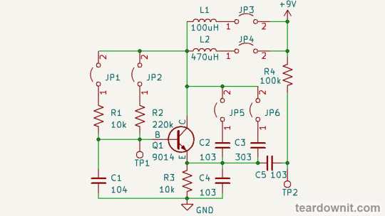
Older versions of the board, if you look closely, had jumpers for you to connect a multimeter as a microammeter and adjust the operation modes of transistors with trim potentiometers, which should be soldered in place of R3, R5, and R7.
However, judging by everyone's experience, these transmitters work perfectly with the included resistors and need no tweaking. Therefore, jumpers were removed from the new versions, but the holes for trim pots were left on the PCB.
The load of the differential amplifier is the LC resonant tank L1C4, and the output is connected to the non-inverting input through capacitor C3. The inverting input is grounded for alternating current by capacitor C5.
We have the Colpitts generator, which we've studied in the previous post! The only difference is that it is assembled not on one transistor but on a three-transistor differential amplifier.
C4 is a variable capacitor for adjusting the oscillation frequency, and L1 is a ferrite rod wound coil of the transmitting magnetic antenna.
The L2 coil connects an oscilloscope, frequency meter, or spectrum analyzer. You can also try connecting an external antenna to it to increase the transmission range. This won't help much because the operating currents of our transmitter are only tens of microamps, but it won't hurt either.
youtube
This transmitter sounds high-quality. Of course, you can clearly hear that this is an AM radio because this is indeed a real AM radio! The quality of FM transmission is much higher, which is one of the main reasons that it has replaced good old AM.
The sine wave on the oscilloscope screen looks nice at first glance. But if we look closely, we will see that the upper half-wave is slightly pointed, and the lower one is rounded and even a little flattened.

From an article about a homemade tube amplifier, we already know that such a waveform indicates a significant presence of the second harmonic and a small admixture of the third harmonic. For a powerful transmitter, this would be bad, but for a compact one, it is fine.

By the way, the eight-transistor superheterodyne in the video is also a DIY project. If you are interested, I can write another post on this and my other radios with a detailed description.
0 notes
Text
Potentiometers and Variable Resistors for Industrial Application
Aeliya Marine Tech provides a range of potentiometers and variable resistors for industrial applications. Our products are durable and reliable. shop now.
0 notes
Text
Digital Potentiometers Market Size, Share, Trends, Growth, Industry Analysis, Key Players, Revenue, Future Development & Forecast 2023-2032

The digital potentiometers market refers to the industry involved in the manufacturing, distribution, and sale of digital potentiometers, also known as digital variable resistors or dig pots. Digital potentiometers are electronic components that mimic the functionality of traditional mechanical potentiometers but provide additional features and advantages.
Digital potentiometers are designed to offer precise and programmable resistance values, making them ideal for applications requiring accurate voltage or current control. They can be digitally controlled using various interfaces such as I2C, SPI, or UART, allowing for easy integration into digital systems.
The market for digital potentiometers has been growing steadily due to their versatility and benefits over traditional potentiometers. Some key factors driving the market growth include:
Advantages over mechanical potentiometers: Digital potentiometers offer benefits like higher precision, greater reliability, smaller size, and resistance to mechanical wear and tear compared to their mechanical counterparts.
Increasing demand for electronic devices: With the growing adoption of electronic devices in various industries, there is a rising need for precise and programmable voltage or current control, which digital potentiometers can provide.
Automation and IoT applications: Digital potentiometers find extensive use in automation and Internet of Things (IoT) applications, where accurate control of electrical parameters is essential. These applications include robotics, industrial control systems, smart homes, automotive electronics, and more.
Growing popularity of wearable devices: The market for wearable devices such as smart watches, fitness trackers, and healthcare monitoring devices is expanding rapidly. Digital potentiometers play a crucial role in these devices by enabling precise control of sensors and actuators.
Advancements in technology: Ongoing advancements in digital potentiometer technology, such as improved resolution, lower power consumption, and increased durability, are driving market growth and attracting new applications.
To obtain a detailed and up-to-date report , I recommend referring to our Stringent datalytics firm, industry publications, and websites that specialize in providing market reports. These sources often offer comprehensive analysis, market trends, growth forecasts, competitive landscape, and other valuable insights into the humidity sensors market.
By visiting our website or contacting us directly, you can explore the availability of specific reports related to the humidity sensors market. These reports often require a purchase or subscription, but we provide comprehensive and in-depth information that can be valuable for businesses, investors, and individuals interested in the market.
Remember to look for recent reports to ensure you have the most current and relevant information.
Click Here, To Get Free Sample Report : https://stringentdatalytics.com/sample-request/digital-potentiometers-market/717/
Market Segmentations:
Global Digital Potentiometers Market: By Company
• Vishay
• Honeywell
• TT Electronics
• ETI Systems
• Bourns
• BEI Sensors
• NTE Electronics
• Haffmann+Krippner
• BI Technologies
• Precision Electronics
• Analog Devices
Global Digital Potentiometers Market: By Type
• High Precision Type
• Standard Type
Global Digital Potentiometers Market: By Application
• Energy Management
• Chemical Industry
• Medical Engineering
• Others
Global Digital Potentiometers Market: Regional Analysis
All the regional segmentation has been studied based on recent and future trends, and the market is forecasted throughout the prediction period. The countries covered in the regional analysis of the Global Digital Potentiometers market report are U.S., Canada, and Mexico in North America, Germany, France, U.K., Russia, Italy, Spain, Turkey, Netherlands, Switzerland, Belgium, and Rest of Europe in Europe, Singapore, Malaysia, Australia, Thailand, Indonesia, Philippines, China, Japan, India, South Korea, Rest of Asia-Pacific (APAC) in the Asia-Pacific (APAC), Saudi Arabia, U.A.E, South Africa, Egypt, Israel, Rest of Middle East and Africa (MEA) as a part of Middle East and Africa (MEA), and Argentina, Brazil, and Rest of South America as part of South America.
Visit Report Page for More Details : https://stringentdatalytics.com/reports/digital-potentiometers-market/717/
Reasons to Purchase Digital Potentiometers Market Report:
• To obtain insights into industry trends and dynamics, including market size, growth rates, and important factors and difficulties. This study offers insightful information on these topics.
• To identify important participants and rivals: This research studies can assist companies in identifying key participants and rivals in their sector, along with their market share, business plans, and strengths and weaknesses.
• To comprehend consumer behavior: these research studies can offer insightful information about customer behavior, including preferences, spending patterns, and demographics.
• To assess market opportunities: These research studies can aid companies in assessing market chances, such as prospective new goods or services, fresh markets, and new trends.
• To make well-informed business decisions: These research reports give companies data-driven insights that they may use to plan their strategy, develop new products, and devise marketing and advertising plans.
In general, market research studies offer companies and organization’s useful data that can aid in making decisions and maintaining competitiveness in their industry. They can offer a strong basis for decision-making, strategy development, and business planning.
Click Here, To Buy Premium Report: https://stringentdatalytics.com/purchase/digital-potentiometers-market/717/?license=single
About US:
Stringent Datalytics offers both custom and syndicated market research reports. Custom market research reports are tailored to a specific client's needs and requirements. These reports provide unique insights into a particular industry or market segment and can help businesses make informed decisions about their strategies and operations.
Syndicated market research reports, on the other hand, are pre-existing reports that are available for purchase by multiple clients. These reports are often produced on a regular basis, such as annually or quarterly, and cover a broad range of industries and market segments. Syndicated reports provide clients with insights into industry trends, market sizes, and competitive landscapes. By offering both custom and syndicated reports, Stringent Datalytics can provide clients with a range of market research solutions that can be customized to their specific needs.
Contact US:
Stringent Datalytics
Contact No - 91-9763384149
Email Id - [email protected]
Web - https://stringentdatalytics.com/
#Digital Potentiometers Market Size#global Digital Potentiometers Market Size#global research market report#global market report
0 notes
Last Seen Blogs

carlistyl
Villian Apologist

yonokom
This Is It

ctow72
Untitled

thebnbwaypropertymanagement
Untitled

littleredwolf
I should be writing.