#Printed Circuit Board Terminal
Explore tagged Tumblr posts
Visit Tumblr Blog
Explore Tumblr blogs with no restrictions, modern design and the best experience.
Last Seen Tumblr Blogs


Fun Fact
Tumblr has 411 employees.
Note
Cactus fascinates me, does it run on code similar to an existing instruction set or is it completely original on that front?
What can you do with it? What's it's storage?
Both the Cactus (the original wooden prototype from years ago) and the new PCB Cactus(es) are essentially derived from a minimal 6502 computer design by Grant Searle for their core logic. Here's what that would look like on a breadboard:
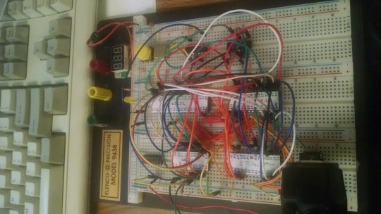
There isn't much to it, it's 32K of RAM, 16K of ROM containing Ohio Scientific's version of Microsoft BASIC, a 6850 ACIA for serial interaction, some logic gates, and of course a 6502 microprocessor (NMOS or CMOS, doesn't matter which). You hook it into a terminal and away you go.
Grant's design in turn can be best described as a distilled, modernized version of the OSI Challenger series of computers. Here's an OSI-400 and a Challenger 4P respectively:

The left one is a replica of the 400 circa 1976, also called the Superboard. It was affordable, endlessly reconfigurable and hackable, but ultimately very limited in capabilities. No BASIC, minimal monitor ROM you talk to over serial, but you could connect it to a bus to augment its features and turn it into a more powerful computer.
Whereas the OSI C4P on the right from about 1979 has more RAM, a video card, keyboard, BASIC built in, serial interface, cassette tape storage, and that's just the standard configuration. There was more room to expand and augment it to your needs inside the chassis (alot changed in 3 years for home computer users).
Grant's minimal 6502 design running OSI BASIC is a good starter project for hobbyists. I learned about the 6502's memory map decoding from his design. I modified and implemented his design on a separate cards that could connect to a larger backplane.
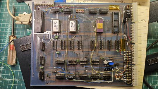
Here are the serial, ROM, RAM, and CPU cards respectively:
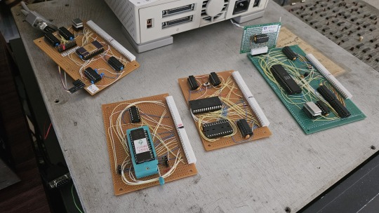
Each one is 100% custom, containing many modifications and fixes as I developed the design. However, that's only half of the computer.
I really wanted a 6502 machine with a front panel. People told me "nobody did that", or couldn't think of examples from the 1970s but that seemed really strange to me. Especially since I had evidence to the contrary in the form of the OSI-300:
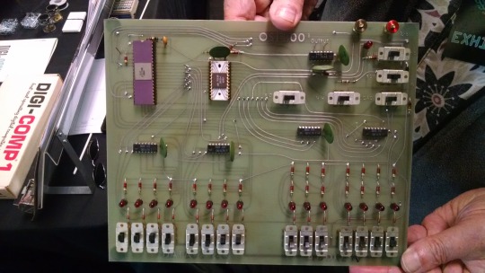
This one I saw at VCF West back in 2018 illustrates just how limited of a design it is. 128 bytes of RAM, no ROM, no serial -- just you, the CPU, and toggle switches and LEDs to learn the CPU. I was inspired the first time I saw one in 2015 at VCF East, which is probably when this whole project got set in motion.
Later that year I bought a kit for a miniature replica OSI-300 made by Christopher Bachman, and learned really quickly how limited the design philosophy for this particular front panel was. It was a major pain in the ass to use (to be clear, that's by OSI's choice, not any fault of Christopher in his implementation)

So... I designed my own. Took awhile, but that's the core of what the Cactus is: my attempt at experiencing the 1970s homebrew scene by building the computer I would have wanted at the time. Over half of the logic in the Cactus is just to run the front panel's state machine, so you can examine and modify the contents of memory without bothering the 6502. I added in all of the things I liked from more advanced front panels I had encountered, and designed it to my liking.
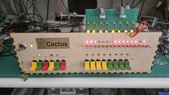
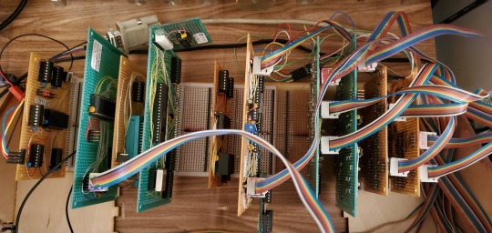
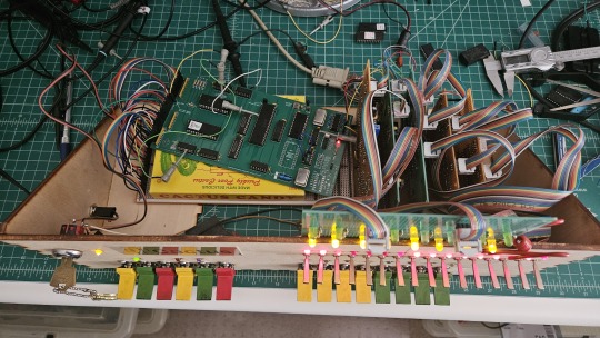
Here's the original front panel, accompanying logic, and backplane connected to the modern single board computer (SBC) version of the machine:
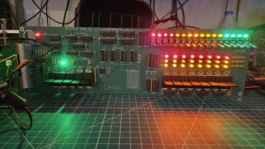
And here's the new Cactus SBC working with the new front panel PCB, which combines the logic, physical switch mountings, and cabling harnesses into a single printed circuit board.
So, what can you do with it? Pretty much the same things I do already with other contemporary 1970s computers: play around in BASIC, fire up the occasional game, and tinker with it.
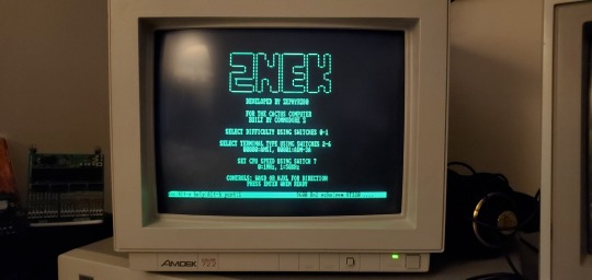
I've got no permanent storage designed for the Cactus as yet, it's been one of those "eventually" things. The good news is that a variety of software can be ported to the hardware without too much trouble for an experienced hobbyist. A friend of mine wrote a game called ZNEK in 6502 assembly which runs from a terminal:
Right now, you have to either toggle in machine programs from the front panel from scratch, burn a custom ROM, or connect it to a serial terminal to gain access to its more advanced features:

Here's it booted into OSI BASIC, but I have also added in a modern descendant of Steve Wozniak's WOZMON software for when I need to do lower level debugging.
I've also got a video card now, based on the OSI-440. I have yet to implement a keyboard, or modify BASIC to use the video board instead of the serial connection. Even if I did, screen resolution is pretty limited at 24x24 characters on screen at once. Still, I'm working on that...


Anyway, I hope that answers your question. Check the tags below to see the whole process stretching back to 2017 if you're curious to learn more of the project's history. I'm also happy to answer any more questions you might have about the project.
267 notes
·
View notes
Text
do not engage (unless it's to your hot ceo and you're drunk)

pairings: katniss everdeen x peeta mellark
blurb:
Katniss has two moods: 1) throw her boss Peeta Mellark into traffic, or 2) throw herself at Peeta Mellark. When a scheming executive tries to bride-nap him, she ends up fake-engaged instead. Now she has to survive corporate espionage, his stupidly perfect forearms, and the mortifying ordeal of being known.

Some people have intrusive thoughts about jumping off cliffs. I have them about licking my boss’s collarbone and pushing him into oncoming traffic — not necessarily in that specific order. I never know, at the start of a workday, which of those two moods will prevail, and it usually ends up being a curious mix of both. And it's not like that's my fault, really, that my boss, Peeta Mellark — seriously, what kind of person names their child after bread — heir to the world's saddest corporate dumpster fire and poster boy for accidental charm, has once again ruined my day simply by existing in my general vicinity with his sleeves rolled up. The office used to be normal before he took over for his father — or, well, as normal as a multi-generational capitalist hellscape run by dead-eyed board members and one nepotism baby can be; now, we just have a designated scream room to preserve the mental sanity of all the employees. It used to be a wellness pod for relaxation, equipped with massage chairs, and a diffuser, and one of those sound bowls. Somewhere along the way the diffuser broke, the chair started shocking people, and now it’s just a soundproofed closet where overworked interns go to cry between budget meetings. Sometimes they scream and cry into a pillow with the CEO’s stupidly beautiful face printed on it.
I pretend I don’t know who keeps ordering those.
(It’s me.)
As I enter his office, he looks at me with darkened eyes and this amused little smile like he can tell I want him to bend me over his desk and make me see stars. I don't know how long I stand there — half a minute at least — and he's saying something something about the coffee in my hand, but I can't hear him over the buzzing in my head, because he's unbuttoned the top two buttons of his dress shirt, and it's short-circuiting my brain.
He grabs the coffee cup from my hands and takes a sip.
I can't breathe.
“Tastes delicious,” he murmurs.
“Thanks. I spit in it.”
His lips twitch. “That explains why it's extra sweet today.”
I narrow my eyes. “I'm going to kill you,” I inform calmly, professionally. “I'm going to murder you, and frame the cafeteria lady.”
“You'd have to get past Delly first,” he says, unphased. “And she likes me.”
Everyone likes him. It's his stupid, beautiful face, and that angelic smile, and how he remembers everyone's names and details, and always stops to ask after them, with his kind eyes and his forearms—
“I'll find a way.”
“Will that be before or after you tell me why you're so grouchy today?”
I roll my eyes. “If you worked for you, you'd be grouchy too.”
“Mm.” Peeta perches on the edge of his desk, sleeves pushed up like he knows what that does to people with eyes, and gives me the kind of smile that makes interns cry in the stairwell. “But you’re especially bloodthirsty today. What happened? Did someone take the last muffin in the break room again?”
“Yes,” I say flatly. “It was you.”
He lifts his brows, all fake-innocent. “Are you sure?”
“You left the wrapper on my keyboard.”
“It could’ve been anyone,” he says, and then grins when I scowl. “You know, you’re very cute when you’re plotting my demise.”
“I’m cute always.”
I immediately regret saying that when he agrees. “That's true but the murder face is definitely a highlight.”
“Don't talk about my face.”
“Would you prefer I write about it then? I'm no poet but I'm sure I could come up with something.”
I should leave. I should turn around, go back to my desk, and scream into the Mellark pillow like a normal employee suffering a standard case of terminal CEO-induced rage. But I don’t. I just stand there like a moron at the gates of hell, mesmerized, because my boss is a golden retriever in a fitted button-down with forearms that have no business being that defined and a voice that could make a nun rethink her vows.
He tilts his head. “You're staring again.”
“I'm plotting ways to kill you.”
“Ah, well,” he says with amusement, “don't let me stop you then.”
He mercifully leaves me alone for the next few hours, buried in back-to-back meetings but the peace is short-lived. Every time he walks by my office, he throws me one of those infuriatingly sweet smiles like he’s not singlehandedly responsible for my slow descent into madness. Honestly, if I ever snap and end up in court, I’m blaming his smile and his sleeves. “Your Honor, I plead guilty to aggravated assault, but in my defense—have you seen him?” When he finally reappears in the doorway of my office, he’s leaned against the frame like we’re in a rom-com where sexual tension is a currency and asks, “Katniss. How do you feel about dinner?” like I’m not currently mentally reviewing OSHA-approved ways to body-slam a person through a plate-glass window.
I finally answer, “I have plans.”
“Then cancel them,” he says, like I just told him I’m free. “I'll pick you up at seven.”
“Cancel— what? Why?”
He rolls his eyes. “So I can kidnap you and chain you up in my tower where I'll have my wicked way with you.” I bite the urge to tell him he doesn't need to lock me up for that. “Seriously, Katniss, it's a work arrangement. I need you there taking notes.”
I look at him with suspicion. “What kind of work arrangement?”
“Dinner.”
“With who?”
“It's irrelevant.”
“Peeta.”
“No, really, it doesn't matter.”
“Peeta.”
He sighs. “It's Drusilla.”
“As in Head of Board of Directors Drusilla? Vampire Drusilla?”
“Yes.”
“Fuck no.”
“Katniss—”
“No. Last time we saw each other, she tried to scratch my eyes out and I ripped out a chunk of her weave. I’m not interested in doing a round two.”
“I’ll fire you if you don’t go.”
“Do it,” I say sweetly. “Please. Put me out of my misery.”
“Katniss.”
“Take Marvel. He’s basically a corporate mannequin. He’ll do great.”
“Marvel has a restraining order from her poodle.”
I blink.
A what? “You’re lying.”
“I wish I were."
“Peeta—”
“Look, she arranged this with a lot of hush-hush so I'm ninety percent sure she's planning something. But she's afraid of you; and if you come along, I'm sure she'll think twice about pulling any tricks.”
I give in. “Fine, but I'm not suffering through it sober.”
He grins. “It won't be that bad.”
“Right,” I say, unconvinced.
Famous last words.
The night is terrible.
And not just the common ‘the food is awful and the conversation is awkward’ kind of terrible. This is the kind of terrible that makes you question your life choices, your sanity, and whether or not you’re actually trapped in a very specific circle of hell that smells like expensive perfume and slow-roasted duck confit. Drusilla Lavellan — head of the board, CEO of passive aggression, and part-time swamp creature masquerading as a socialite — is wearing what I can only assume is the entire cosmetics section of a makeup store on her face. Thick layers of foundation in a shade that doesn’t exist in nature, contoured cheekbones sharp enough to cut glass, eyebrows arched like she’s constantly judging your existence (spoiler: she is), and lips outlined in her signature color that is best described as dried blood, which has only ever solidified the conspiracy going around our office that she is some kind of a bloodsucking vampire. There's a wig perched on her head, voluminous, blond, stiff, and slightly askew — which turns a lot of heads for entirely wrong reasons — and she talks in a frequency so high that I drown out her voice out of habit. I'm not concerned with paying attention. My only job is to sit here and glower occassionally when Peeta looks uncomfortable. Which is often, because she keeps eying him like he's the last item on a buffet, and she's got coupons. So far, she has managed to imply she would be happy to throw her support behind his ascension as the CEO, which is very contentious and unpopular right now because of the mess his father left, but in return for something she doesn't seem to want to reveal before me.
But she must have gotten over her reserve over my company soon because then comes the strangest part of the night.
I choke on my drink.
Peeta looks alarmed. “You're proposing what?”
“Marriage, of course,” she says like it's a given. “You’re young and handsome. Are you surprised I'd want you?”
“I'm surprised you think he'd want you,” I say, emboldened by my seventh glass of wine and a lack of will to live.
She ignores me.
Peeta flails around for a response. “But we don't know each other.”
“What's that got to do with anything?” she frowns, confused. “It’s a great business move. Romanticism is for children, and we're all adults here, aren't we?”
“But I — I can't.”
“Why not?”
“Because I'm already engaged,” he's smoother now, calmer, as he smiles and reaches for my hand. The fog of alcohol clears up just in time for him to lift up my hand on which he's somehow slid on a ring — one of the ones I've seen on his own hand — slightly dangling from my hands. “To Katniss.”
Drusilla gapes.
I gape.
Everyone and their mom gapes.
“You're engaged?” she says, voice raising another decibel.
I stare. “We are?”
“We are.” Peeta cheerfully leans over and presses a kiss to my cheek. “Katniss wanted to keep it private for a while.”
“I did?”
“Mhmm.”
The alcohol has murdered every functioning brain cell I had. I nod along, because sure. Why not. Reality is a construct and I’ve decided to opt out.
It can't be that bad.
(I'm wrong.)
Because right behind Drusilla — standing with the posture of a man who smells scandal for breakfast — is a cameraman. And right next to him is Plutarch Heavensbee: corporate gossip merchant, board puppet, and part-time vulture. He’s been writing hit pieces on Peeta since the day he inherited the company — everything from drug abuse (false), to playboy behavior (debatable), to outright incompetence (still debatable). And now he’s here, watching all this unfold like it’s his birthday. Before I can stop myself, I surge to my feet, ready to throw hands, or at the very least, hurl a breadstick at Drusilla’s beady little eyes for trying to paparazzi-marry my boss under duress. But the universe hates me, so my heel catches on the edge of the tablecloth and I immediately stumble.
Peeta catches me with reflexes that should be illegal. His arm wraps around my waist, steady and warm, as he murmurs something calming — probably to me, maybe to the table, hard to tell — while the camera flashes explode like fireworks and Plutarch’s smug, greasy smile stretches wider.
I should be screaming. I should be plotting my escape. I should be wondering how I let myself get fake-engaged to my golden retriever boss in front of corporate America.
Instead, I do the worst thing possible.
I lean into him.
And smile for the camera.
Which is how I accidentally end up fakely real married to my boss, start a corporate war, and develop a sudden allergy to press releases— but well.
That's a story for another time.
this cringe-fest was in my drafts for days and days because i couldn't decide if i like it or i hate it, so there you go; hope you liked it! if you did, please comment, like and reblog! any and all feedback is appreciated.
#everlark#katniss x peeta#everlark fanfiction#the hunger games#thg fanfiction#thg#the hunger games fanfiction#katniss everdeen#peeta mellark#thg katniss#thg peeta#thg headcanons
39 notes
·
View notes
Text
On Bodging Silly Mistakes
After a few weeks of rest and working on non-homebrew-related projects since getting my 68030 stack running 8-user BASIC, I've circled back around to the project. My goal is to have it ready to exhibit for VCF Southwest 2025 in June.
The first thing to do when picking up an old project is to make sure it still works to begin with.
It did not.
The computer would start up, go through its boot process, and start the user programs. The supervisor terminal would accept and execute commands, but none of the user terminals would accept input.
I could tell the serial data was making it to the machine, because my 8-port serial card has indicator LEDs on the Transmit & Receive signals and they were working as expected. If I held down a key as the system booted, it would print that character a few times before stopping and then no longer accept any more data. So it really looked like the hardware was working. Nothing had changed in software so that wasn't likely to be the issue.
It reminded me of the problems I encountered with reading from disk when CPU cache was preventing the updated disk status bit from being read. The serial card supports asserting the CPU's Cache Inhibit signal, but perhaps that circuit wasn't functioning. There was no change with it connected or not. Time to break out the oscilloscope. The Cache Inhibit signal was always low — always asserted. Cache wasn't the problem because cache was effectively always disabled.
Out of ideas, it was time to break out the logic analyzer. The I/O Read & Write signals on the serial card were working as expected, and it was properly addressing the card & its individual ports. So next thing was to check was the actual data being read from the UARTs.
Letting the logic analyzer run and watching the data fly through, the problem finally made itself known — the UARTs were not setting bit 0 of the status byte to indicate that they had received data. The data was getting to the UART, it just wasn't acknowledged.
But why? And why did it work initially on restart and then stop? And why did it work without issue a few weeks ago? What is different?
What is different, indeed. I have made one change to the hardware since I last ran it — I added a proper watchdog/power-on-reset controller. If the power supply drops below 4.7 volts, it will reset the computer. The power supply I had been using was marginal and was getting caught by the watchdog, so I switched to a proper power PC supply.
So what's different since last time I ran the system is my reset circuit is more effective and the system voltage should be much more stable 5V.
And that's when I realized a mistake I made in the design for my 8-port serial card. The 68k reset signal is active-low and the 16C55x UART reset signal is active-high. I was trying to minimize part count, and didn't have an inverter for the reset signal, so I used what I had on hand — a buffer with an active-low enable signal.

Anyone well-versed in electronics may already see the problem.
When the CPU-RESET# signal is asserted (low), the buffer will set its output, IO-RESET to match its input, VCC (high). That's great, we get a high signal on the output whenever the CPU Reset signal is low.
Except ... what happens when the CPU Reset signal is not asserted? The buffer goes open-collector and doesn't pull the IO-RESET signal one way or the other; it's just left floating.
Floating signals are bad news for digital circuits. Their behavior is unpredictable and subject to environmental noise, power fluctuations, etc. For my IO-RESET signal to function properly, something needs to pull it low whenever the 74'125 buffer is not actively driving it high. A good-sized pull-down resistor should do the job just fine, so I dug through my stock and found a 3.65k surface-mount resistor and bodged it onto the back side of the board.

And sure enough, that fixed the problem!
It is possible that when I was running the system on that marginal power supply previously, the IO-RESET signal was able to stay just low enough to not trigger reset on the UARTs. Or it could have just been different environmental factors.
I'm glad I took the time to test the machine today, and I'm glad this bug came up. It's the kind of bug that could easily have come up when running in a new environment for the first time — such as on the show floor at VCFSW. Far better to run into a bug like this at home with access to all of the tools (and time) to figure it out.
Now that things are up and running again I can continue my testing and setup for VCFSW.
#homebrew computing#homebrew computer#vintage computing#motorola 68030#motorola 68k#mc68030#wrap030#vcfsw
16 notes
·
View notes
Note
Hi, I'm the human who got trapped inside a TARDIS.
Thank you for the help, I managed to open the interior doors a few days ago and went looking for the owner. No luck, but I found a swimming pool, a huge library, kitchens, bathrooms, bedrooms, science labs, entertainment rooms and what seems to be a huge park?
I don't know how on Earth something like this can even exist, but I guess there's all the time in the world to learn while waiting for rescue. I'm worried about the pilot though; isn't there a way to locate them, given how advanced this craft is?
Hi there, trapped human! Let's address your concerns about the pilot.
How to locate a TARDIS pilot
Do not attempt to operate the TARDIS flight controls without being absolutely sure it is safe. On earlier models, use of the console without a Symbiotic Nucleus may result in injury or a very slow and painful death.
Note: Most of the systems are in Gallifreyan. TARDISes do not tend to translate Gallifreyan, so you may not be able to read them.
Here are some methods you can try:
📡 Stattenheim Remote Teleport Control: Look for a small black disc stored in a transparent dome on the console. If properly calibrated, pressing this button may immediately transport you to the pilot. If it's not there, the pilot has taken it, or the TARDIS doesn't have the Mark X refit.
⏪ Fast Return Switch: This will return the TARDIS to an approximate time and location near where it last landed. It's clearly labelled on the console. Turn it clockwise to operate. [Use with caution]
📍 Locate the Doctor: Some models may have this feature. It is activated by pressing a button on the console labelled 'LTD' (your TARDIS may have another personalised variation). The Visual Display Unit will show the pilot's relative position on a map.
🧬 Passenger Adoption Scanning Terminal (PAST): This system registers and protects passengers. Due to how it works, if you’re registered, the pilot is likely still on board.
👥 Internal Monitor: A Mark II TARDIS can detect the number of sapient life forms onboard and display it on the Internal Monitor.
💻 The Scanner: The Scanner can locate the pilot's biodata within a two-mile radius outside the TARDIS. Some pilots have a preprogrammed switch by the scanner that will instantly display their pilot's location, but this is a modified feature.
🎤 Voice Interaction: Try speaking to the TARDIS. Some models respond to vocal commands for minor systems. If the TARDIS doesn’t respond, your voice print registration is required.
🔍 Artron Telepathic Radiation: If you find another Time Lord, they can scan for the pilot's ‘thumbprints’ left by their symbiotic nuclei to identify them.
🛠️ Cloister Room: This room contains telepathic circuits to communicate with the pilot, possibly providing an audiovisual link. It's accessible via a shortcut in the Secondary Control Room. Be cautious, as this room may have minor effects on your nervous system.
🚨 Extreme Emergency Lever: Crew members can use this lever to lock onto a pilot drifting in space and materialise around them.
🗝️ TARDIS Key: Use a key to locate anyone processed by the PAST (such as other crew members). Mix their blood with saline solution, coat the key, and suspend it in clear oil. The oxidised blood particles will 'point' in their direction.
🧠 Memory Store: Stores memories of TARDIS occupants, including audio-visual recordings of the Control Room. Useful to identify the pilot and the last time they were there.
💉 Medical Bay: The Automatic Diagnostic Terminal usually uses the pilot's avatar to communicate. You may be able to ask the avatar their identity, although responses may be limited.
If you need to take emergency action:
There is an 🚪Emergency Door located in the Power Stacks Room, leading outside. The 🚨 Fail-Safe Switch locks the TARDIS onto the nearest habitable environment, creating emergency doors. The 🆘 Emergency Emergency System (so emergent they named it twice) creates a wormhole to the nearest habitable planet. This is one way only, so there is no return to the TARDIS afterwards.
💀 Pilot Death & TARDIS Adoption
Usually, emergency systems will try to lock onto the pilot. If this is not happening, the pilot may have died without regeneration. TARDISes will normally go into a period of mourning following the death of their pilot, possibly involving a loss of power or shut down of many systems.
If you're finding systems are not shut down but have increasing suspicions the pilot may have died, this could be because:
The TARDIS has already gone through its period of mourning;
It has reactivated at your presence, hoping to establish a link with you;
It didn't really like its pilot very much.
It's not unheard of for humans to forge a bond with the TARDIS, especially if it's been left alone for some time. The TARDIS might be adopting you as its new caretaker, which would explain the access you've been granted. Some clues:
🎁 TARDISes sometimes leave gifts to welcome new arrivals. Look around for anything unusual or out of place.
💭 If you feel any strong intuitive pushes or thoughts, it might be the TARDIS trying to communicate with you.
🔑 If you're finding you have access to a lot of the TARDIS (including intricate systems), the TARDIS definitely likes you.
🏫 So ...
To locate the pilot or other crew members, try any of the procedures outlined above. Be sure to familiarise yourself with the main areas and secure access to food, water, and other necessities. The TARDIS can help—look for glowing arrows or symbols on the walls. These can lead you to important areas. Remember, the TARDIS is a complex and sentient machine. If it has adopted you, it will do its best to keep you safe, and it has a plethora of effective automated defences to achieve this.
Related:
🤔|🧬🛸What's the link between a Time Lord and their TARDIS?
💬|🧬🛸How does TARDIS symbiosis work for individuals and groups?: Details on this special Time Lord-TARDIS connection.
💬|🧬🛸How long can a bonded Time Lord be away from their TARDIS?: If extended absences can impact symbiosis, and also annoy your TARDIS.
Hope that helped! 😃
Any orange text is educated guesswork or theoretical. More content ... →📫Got a question? | 📚Complete list of Q+A and factoids →📢Announcements |🩻Biology |🗨️Language |🕰️Throwbacks |🤓Facts → Features: ⭐Guest Posts | 🍜Chomp Chomp with Myishu →🫀Gallifreyan Anatomy and Physiology Guide (pending) →⚕️Gallifreyan Emergency Medicine Guides →📝Source list (WIP) →📜Masterpost If you're finding your happy place in this part of the internet, feel free to buy a coffee to help keep our exhausted human conscious. She works full-time in medicine and is so very tired 😴
#gallifrey institute for learning#dr who#dw eu#ask answered#whoniverse#doctor who#gallifreyan culture#tardis#GIL: Asks#GIL: Biology/Foundations#GIL: Biology#GIL: Species/TARDISes#GIL: Species/Gallifreyans#GIL: Gallifrey/Technology#GIL
27 notes
·
View notes
Note
☕
For Oleander!
@the-haunted-office
Ed presses his lips into a fine line and eyes the mug in front of him in suspicion. It's black with green lines like a circuit board and 'Oleander' printed in a green retro font, like it's been typed out on a an old computer terminal.
"We're seriously doing this again?" he asks. His lips turn downward in displeasure on confirmation. "Let me guess. It's actually oleander. Tea made from the flowers. Which are poisonous."
Ed scowls. "If I die, I will find a way to come back and haunt you."
With that, he picks up the mug, and raises it to his lips to take a sip." his lips immediately pucker up from how bitter it is.
"It tastes like lime juice," he says flatly. "Concentrated lime juice... and salt." He frowns. "Though... there's some after taste. Something sweet. Coconut, maybe?"
It doesn't immediately appear to have any sort of healing power, or if it does, it is very slow. Though, at the same time he hasn't keeled over on the spot from drinking it, so it turns out it wasn't poison.
1 note
·
View note
Text
"Why Wire-to-Board Connectors Matter in Today's Tech Landscape"
In the ever-evolving landscape of electronics and electrical engineering, wire-to-board (WTB) connectors are fundamental components that provide a secure, efficient link between a set of discrete wires and a printed circuit board (PCB). Despite their small size, these connectors are indispensable in a wide range of applications—from consumer electronics and automotive systems to industrial machinery and telecommunications.Get more news about Wire-to-board Connector,you can vist our website!
What Are Wire-to-Board Connectors? Wire-to-board connectors are used to route electrical signals or power from individual wires onto a printed circuit board. Unlike board-to-board connectors that facilitate connections between PCBs or wire-to-wire connectors that link individual wire sets, WTB connectors interface directly between a cable harness and the board, typically through soldering or press-fit terminals. This facilitates modular design, ease of maintenance, and scalable manufacturing.
They consist of two primary components: the plug (housing the wires) and the receptacle or header (mounted on the PCB). These connectors are available in various pitches (the center-to-center spacing between pins) and configurations (vertical or right-angle orientations), making them adaptable for a variety of design constraints and spatial limitations.
Key Features and Considerations Designers and engineers often evaluate several critical factors when selecting WTB connectors:
Current and Voltage Ratings: Depending on the application, connectors must meet safety and performance thresholds.
Pitch Size: Fine-pitch connectors (≤1 mm) allow for compact design, while larger pitches offer greater robustness.
Locking Mechanisms: Latch or friction locks ensure secure connections that resist vibration or accidental disconnection.
Material and Plating: Contact materials, often copper alloys with gold or tin plating, influence conductivity and longevity.
Environmental Resilience: Some WTB connectors are designed for harsh environments with resistance to moisture, dust, or high temperature.
Applications Across Industries The versatility of wire-to-board connectors is reflected in their widespread use across diverse industries:
Consumer Electronics: Used in smartphones, laptops, and wearable devices for internal signal and power connections.
Automotive: Essential for infotainment systems, sensors, and electronic control units (ECUs), where compact, vibration-resistant connectors are critical.
Medical Equipment: Connectors must meet stringent reliability and safety standards in devices like diagnostic equipment and patient monitors.
Industrial Automation: WTB connectors facilitate modular assembly and simplify maintenance for sensors, controllers, and interface devices.
Trends and Innovations Modern trends push the boundaries of connector miniaturization and performance. As electronic devices become more compact and sophisticated, the demand for high-density connectors with increased signal integrity and EMI shielding continues to grow. Additionally, some manufacturers are integrating features like surface-mount technology (SMT) compatibility and automated cable termination to streamline production and assembly.
Another key trend is the development of eco-friendly, RoHS-compliant connectors to meet global environmental standards while ensuring high performance. With the rise of Industry 4.0 and the Internet of Things (IoT), wire-to-board connectors are playing an increasingly strategic role in enabling smart, connected systems.
Conclusion Although often overlooked compared to high-profile semiconductors or processors, wire-to-board connectors are vital enablers of modern electronic innovation. Their reliability, precision, and adaptability allow designers to build smaller, more powerful, and more efficient systems. As technology continues to advance, the humble WTB connector will remain a quiet but essential hero in the background—connecting ideas to reality, one circuit at a time.
0 notes
Text
A Simple Guide: Phoenix Contact Devices and Their Types
Technology keeps evolving, making electrical connections more reliable and efficient. Industries depend on high-quality connectors to ensure stable and secure connections in various applications. Phoenix Contact is known to provide advanced connection solutions for different industrial needs. From power distribution to automation, these devices help businesses maintain smooth operations. The top trading and contracting company in Muscat supplies Phoenix Contact devices, ensuring industries get reliable and durable connectors. In this article, we will discuss five types of Phoenix Contact device connectors and their uses.
Types of Phoenix Contact Device Connectors
PCB Terminal Blocks: PCB terminal blocks are essential for connecting wires to a printed circuit board. These connectors come in different sizes and designs to suit various industrial applications. They provide a secure and vibration-resistant connection, making them a reliable choice for automation systems and power electronics.
Heavy-Duty Connectors: Heavy-duty connectors are built to withstand harsh environments, including extreme temperatures, dust, and moisture. They are commonly used in industrial machinery, transportation, and power plants. Many businesses seek Phoenix contact distributors in Oman to get these connectors for their high durability and safety.
Circular Connectors: Circular connectors are widely used in automation and robotics. They offer a compact design with secure locking mechanisms, ensuring a stable connection in moving parts. These connectors are known for their excellent signal transmission, making them ideal for applications requiring continuous communication between devices.
Data Connectors: Data connectors ensure secure data transmission in industrial networks. They support Ethernet, USB, and fibre optic connections, allowing smooth communication between machines and control systems. These connectors play a key role in smart factories and automated production lines, improving efficiency and reliability. Their durable design helps industries maintain stable data flow, making them essential for modern industrial automation and networking solutions.
Power Connectors: Power connectors provide reliable power transmission in industrial setups. They ensure a stable electricity supply to various devices, reducing the risk of connection failures. These connectors are designed for high efficiency and durability, making them ideal for demanding applications. Many industries, including the top trading and contracting company in Muscat, choose these connectors for their superior performance and long-lasting quality, ensuring smooth and uninterrupted operations in industrial environments.
Wrapping UpPhoenix Contact devices offer advanced solutions for different industrial applications. Their wide range of connectors ensures safe and efficient electrical connections in various sectors. Businesses looking for high-quality connectors often rely on Phoenix contact distributors in Oman to meet their specific needs. With the right connectors, industries can improve efficiency and ensure reliable operations.
0 notes
Text
SA-10 Solder Assist Tool Set (6 in 1) (WLXY)
Practical WLXY SA – 10 6 in 1 Assist Welding Tools Solder Assignments. These solder assist tools can be widely used in printed circuit board assembly and maintenance of the welding operation of the shape of different terminals. Black carbon steel refined, durable and convenient. Best matched for repair and assembly work. Variety of application for precision work. To meet the welding operation…
0 notes
Text
Brass Electronic Components and Brass Inserts: The Backbone of Precision Engineering
Brass is a widely used metal in the manufacturing industry due to its excellent electrical conductivity, corrosion resistance, and durability. Among the various applications, brass electronic components and brass inserts play a crucial role in various industries, including electronics, automotive, and telecommunications. Their precision, versatility, and strength make them an indispensable choice for manufacturers worldwide.
Brass Electronic Components: Enhancing Efficiency and Durability
Brass electronic components are widely used in electrical and electronic devices due to their superior conductivity and resistance to oxidation. These components include:
Connectors and Terminals: Brass connectors ensure a stable electrical connection, making them ideal for circuit boards, switches, and power distribution systems.
PCB Mounts and Contacts: Used in printed circuit boards (PCBs), these brass components provide a secure and reliable connection between electronic parts.
Brass Pins and Sockets: Found in various electrical applications, they enhance the durability and functionality of electronic systems.
The high machinability of brass allows manufacturers to produce intricate and precise electronic components with minimal material wastage. Additionally, brass has a natural resistance to corrosion, ensuring the longevity of electronic devices.
Brass Inserts: A Perfect Fit for Stronger Joints
Brass inserts are essential for industries that require strong and long-lasting fastening solutions. These inserts are commonly used in:
Plastic Molding: Brass inserts are embedded into plastic components to create durable threaded joints. They enhance the strength of plastic parts and prevent wear and tear over time.
Automotive Industry: These inserts provide secure fastening in vehicle parts, ensuring stability and durability under high-stress conditions.
Furniture and Construction: Brass inserts offer a reliable solution for assembling furniture and structural applications, where strong threaded connections are essential.
Brass inserts come in various types, including threaded, press-fit, and ultrasonic inserts, catering to different manufacturing needs. The anti-corrosive nature of brass makes these inserts suitable for both indoor and outdoor applications.
Conclusion
The demand for brass electronic components and brass inserts continues to grow as industries seek durable and efficient solutions for electrical and mechanical applications. Their excellent conductivity, corrosion resistance, and strength make brass the ideal material for a wide range of products. Whether in electronics, automotive, or construction, brass components play a vital role in ensuring precision, reliability, and longevity in modern manufacturing.
0 notes
Text
Best Quality Copper Sheets Manufacturers in India
Copper Sheets Manufacturers in India: A Focus on KMW India
Copper, one of the oldest metals known to humans, has been utilized for various industrial applications for centuries. Today, copper sheets are indispensable in numerous industries such as electrical, construction, automotive, and manufacturing due to their superior conductivity, malleability, and resistance to corrosion. India, with its growing industrial sector, is home to severalcopper sheet manufacturers in india, one of the prominent names being Krishna Metal Works (KMW), a leading supplier in the Indian market. This article explores the role of copper sheet manufacturers in India, with a particular focus on KMW India and its contributions to the industry.
Overview of Copper Sheets and Their Importance
Copper sheets are thin, flat, and flexible plates of copper, which are essential in various industries, primarily due to copper’s excellent electrical conductivity and thermal properties. They are used in applications ranging from electronics to decorative designs, plumbing, and even in the production of heat exchangers. The demand for copper sheets is especially high in industries that rely on high-performance materials for electrical wiring, transmission systems, and components like terminals, conductors, and even PCB (printed circuit board) manufacturing.
Copper’s properties—its ability to resist corrosion, its durability, and its conductivity—make it ideal for these purposes. The material’s natural resistance to rust and oxidation ensures a longer life cycle in harsh environments, thus lowering maintenance and replacement costs.
Copper Sheet Manufacturers in India
India has a robust manufacturing industry, and copper products, including copper sheets, are a significant part of this landscape. Several companies across the country manufacture copper sheets, catering to various industries. Copper sheet manufacturers in India are crucial not just for domestic supply but also for meeting international standards.
The Indian copper industry is well-supported by both large public and private enterprises, including manufacturers and suppliers who cater to a wide range of industrial needs. The key factors driving the growth of copper sheet manufacturers in India include an expanding electronics sector, growing demand for renewable energy solutions, and the increasing need for electrical power transmission infrastructure.
Among these manufacturers, Krishna Metal Works (KMW) stands out for its exceptional copper sheet products, competitive pricing, and commitment to quality. KMW India is a leader in the production of high-quality copper sheets and offers a wide variety of copper products that meet the diverse needs of industries ranging from automotive to electronics and construction.
KMW India: A Leading Manufacturer of Copper Sheets
Krishna Metal Works is a trusted name in the Indian copper sheet manufacturing industry. The company has built a reputation for delivering high-quality copper sheets that adhere to stringent international standards. Established with a vision to provide premium copper products, KMW India has become a preferred choice for customers in India and abroad.
KMW India specializes in producing copper sheets of various grades, including Electrolytic Tough Pitch (ETP) Copper (99.90% Cu), Deoxidized High Phosphorus (DHP) Copper (99.80% Cu), and TBC Copper (99.60% Cu). Each of these grades offers unique properties suitable for specific applications, ensuring that KMW’s products meet the precise requirements of various industries.
Product Range and Specifications
KMW India manufactures copper sheets in a range of thicknesses, widths, and lengths, ensuring that customers receive tailor-made solutions for their needs. The thickness of copper sheets ranges from 0.10 mm to 16 mm, and they are available in widths from 15 mm to 1350 mm and lengths from 50 mm to 3000 mm. This variety of dimensions allows customers to select the right size and shape of copper sheets for their specific projects.
Additionally, KMW India offers copper sheets manufactures in india various tempers, including soft, half-hard, and full-hard, providing flexibility depending on the application requirements. The company ensures precision in manufacturing, resulting in products that exhibit excellent surface finish and dimensional accuracy. KMW’s copper sheets are also available in a range of finishes, such as bright, dull, and matte, depending on the aesthetic and functional needs.
Key Features of KMW Copper Sheets
High Electrical Conductivity: KMW’s copper sheets deliver superior electrical conductivity, making them ideal for use in power transmission, electrical wiring, and other high-performance electrical applications.
Corrosion Resistance: KMW copper sheets have excellent resistance to corrosion, making them perfect for outdoor applications and industries where moisture exposure is common.
Durability: KMW copper sheets are long-lasting, offering extended service life in industries like automotive, manufacturing, and energy.
Customization: KMW India offers copper sheets in various grades, dimensions, and finishes, enabling customers to choose products based on their specific needs.
Applications of KMW Copper Sheets
KMW copper sheets are widely used across several industries, including:
Electrical Industry: Due to their excellent conductivity, copper sheets are used in electrical applications such as electrical components, terminals, conductors, and connectors.
Construction and Plumbing: Copper’s resistance to corrosion makes it ideal for plumbing and building construction, especially in areas requiring durability and longevity.
Automotive and Manufacturing: Copper is used in various parts of vehicles and manufacturing equipment, including heat exchangers, radiators, and other components that need superior thermal conductivity.
Renewable Energy: KMW’s copper sheets are also used in renewable energy applications, such as solar panels and other energy-efficient products, contributing to the growing green energy sector.
Conclusion
The demand for copper sheets in India continues to rise, driven by the expanding industrial sectors, particularly in electrical, automotive, and construction applications. Copper sheet manufacturers like KMW India have become vital players in this growth, offering high-quality products tailored to meet the diverse needs of various industries. By adhering to strict quality standards and providing customized solutions, KMW India continues to lead the way in copper sheet production in India, contributing significantly to the nation’s manufacturing prowess.
Visit:- https://www.kmwindia.com/copper-sheets.html
1 note
·
View note
Text
Comparing Reflow (THR/SMT) vs. Wave/Manual (THT) Soldering for Pluggable Terminal Blocks

Integrating terminal blocks into industrial applications requires careful consideration of the soldering process. Terminal blocks, which provide secure connections for electrical systems, come in two main forms: through-hole technology (THT) and surface-mount technology (SMT). These two methods involve different soldering techniques—wave/manual (THT) and reflow (THR/SMT). The choice of soldering process significantly impacts production speed, cost, and the overall quality of the finished product. Understanding the differences between these methods is crucial for manufacturers to make the right decisions for their assembly lines.
Differences Between THT (Wave/Manual) and THR/SMT (Reflow) for Industrial PCB Assembly
The primary difference between THT and SMT lies in how the terminal block is attached to the printed circuit board (PCB). THT involves inserting the terminal block’s pins through holes in the PCB, followed by soldering, usually via wave soldering or manual soldering. In contrast, SMT (including THR) places terminal blocks directly on the surface of the PCB, and soldering is typically done through a reflow process.
THT soldering is commonly used for larger, more robust terminal blocks, providing strong mechanical connections suitable for high-stress environments. SMT, on the other hand, is more suited for smaller, compact terminal blocks, offering high-density solutions and more automated assembly. Reflow soldering allows for precise control of temperature, reducing the risk of thermal damage to sensitive components, while wave soldering is more cost-effective for large-volume production, but it can be less accurate in comparison.
How Choosing the Right Process Affects Production Speed, Cost, and Quality The choice of soldering method directly impacts production speed, cost, and quality. THT (wave/manual) soldering is often slower and requires more manual labor, making it more expensive in smaller batches but effective for heavy-duty or high-reliability applications. Reflow soldering (THR/SMT) speeds up the production process with automation, making it more cost-efficient for mass production, though it may not provide the same level of mechanical robustness for certain heavy-duty applications.
In terms of quality, SMT soldering provides a cleaner finish with fewer defects such as cold solder joints, making it ideal for precision applications. THT soldering, on the other hand, excels in providing a stronger mechanical bond that is essential in demanding or high-vibration environments.
Best Practices
When choosing the best soldering method, manufacturers should consider factors like pin spacing and conductor entry designs. For THT soldering, larger pin spacings may be more appropriate for ease of manual or wave soldering, while tighter spacing in SMT applications allows for more compact, efficient designs.
In both cases, ensuring strong mechanical and electrical connections is vital. In harsh environments, terminal blocks must resist vibration, temperature fluctuations, and moisture, so selecting the right soldering method and design ensures reliable connections and long-lasting performance.
Conclusion
Choosing between reflow (THR/SMT) and wave/manual (THT) soldering for Pluggable Terminal Blocks is an important decision for manufacturers. Each method has its strengths and applications, with THT offering robust mechanical connections and SMT providing precise, efficient assembly. Manufacturers must carefully weigh production methods based on their specific needs, balancing speed, cost, and quality to achieve the best results for their terminal block integration.
0 notes
Text

Digilogic Systems Pvt. Ltd. is an AS9100D & ISO 9001–2015 certified company with 17+ years of Industry expertise in quality Test, Measurement and Simulation solutions for the Defence and Aerospace sectors.
Our Technical Expertise and Capabilities:
Electronic Warfare (EW) Solutions
Radar Testing & Evaluation Systems
Electromechanical Testing Solutions
SATCOM Hub & Terminal Solutions
Propulsion Motor Testing Solutions
Software-Defined Radio (SDR) & Communication Test Systems
Underwater Test, Calibration & Validation Solutions
Fire Control System Testing & Integration
Digilogic Systems has vast experience in this field and specializes in the design, manufacturing and support of cutting-edge solutions including
Automatic Test Equipment (ATE),
Simulators for testing systems (ranging from DC to 40GHz),
Data acquisition & control systems,
Ground Check-out systems,
Radar & EW simulators
and associated services intended for the Development, Integration, Production and Maintenance of Electronic Systems.
Digilogic Systems is dedicated to providing comprehensive “Turnkey Solutions”. Whether you need to test an RF sub-system or a generic printed circuit board, we excel in offering automated test solutions that eliminate laborious manual procedures while remaining within your budget and ensuring maximum return on investment.
For more information (or) to request a quote, Contact us.
Website: www.digilogicsystems.com
Head office: Hyderabad
Phone: 040 4547 4601
Branch office: Bengaluru
Phone: 080 4975 6034
Email: [email protected]
0 notes
Text
Review, teardown, and testing of ERPF-400-24 Mean Well power supply
General Description

Brief Specification: ERPF-400-24 is a power supply unit with a 24-volt DC output and a rated current of up to 16.7 amps. According to the specification, the unit has an extended operating range for AC input voltage from 90 to 264 V. However, with an input voltage between 90 and 200 V, the unit can only deliver 50% of its rated power. It can also operate from a DC input within the range of 127 to 370 V.

The unit has dimensions of around 9x5x2 inches (220x130x48 mm exactly), is built on a printed circuit board housed in a stamped metal case, and is designed to operate with no forced cooling. The board is installed into the case, like in a tray, and is covered with a compound (most likely thermally conductive), making it non-removable for repair. The unit is covered with a perforated lid on top.
It features an LED indicator for output voltage and allows adjustment of the output voltage within a range of -5% to +10%. The unit includes an active PFC (Power Factor Correction) circuit and has a high power factor of up to 0.98 at 115 VAC. It also has thermal protection, with temperature monitoring performed using a thermistor placed on the output rectifier diodes. Traditional safe measures, such as overload and overvoltage protection, are also provided.
Circuit and construction description: Unfortunately, the compound filling makes detailed examination of the circuit difficult, so there is a high probability of interpretation errors. However, it appears that the design shares many similarities with the RSP-320-24 (https://teardownit.com/posts/review-teardown-and-testing-of-rsp-320-24-mean-well-power-supply) power supply unit, in both circuit and layout. This suggests that the ERPF-400 may be controlled by the FAN4800 controller, just like the RSP-320.
The input and output terminals are mounted on a common screw terminal block (1). The terminal block's connections from top to bottom are as follows: three terminals for phase, neutral, and ground (input), and three parallel terminals for the output, ground, and +24V. The input voltage from the terminal block (1) passes through an EMI filter (3) and then to the diode bridge (5). A varistor (2) is installed at the filter's input to suppress dangerous voltage spikes. The rectified voltage from the bridge (5) is then routed through an NTC inrush current limiter (4) to the active PFC circuit. The PFC's power stage consists of a transistor (6), inductor (11), diode (7), and output capacitor (8). The rectified and filtered voltage from capacitor (8) is fed into a forward converter, which comprises transistors (9) and transformer (10). The voltage from the transformer's output winding (10) is rectified by diodes (12) and filtered by an output LC filter (13) (14).
The filter’s output capacitance is provided by four 560µF, 35V capacitors rated for operation at up to 220°F or 105°C (13).
The transformer's core (10) is tied in a metal clamp, which is bolted to the case. This design likely serves to dissipate heat from the transformer.
Due to the presence of the compound, it is difficult to assess the overall build quality. The compound itself has been applied somewhat carelessly, with visible splatters and drips. Furthermore, there are gaps in the compound application, significantly reducing its protective effectiveness.


The LED output voltage indicator and output voltage adjustment resistor (16) are located near the terminal block, allowing access without removing the top cover.
Test Conditions
Most tests were conducted using Test Circuit 1 (see appendix) at 80°F (27°C), 70% humidity, and 29.8 inHg pressure. Unless otherwise specified, measurements were taken without pre-warming the power supply, and the operating mode was momentary load. Input voltage was set to 115V AC, and the current of 8.4 A was considered 100%. The following values were used to determine load levels:

Output voltage with static load

The unit demonstrates excellent output voltage stability.
Startup Characteristics
Startup at 100% load
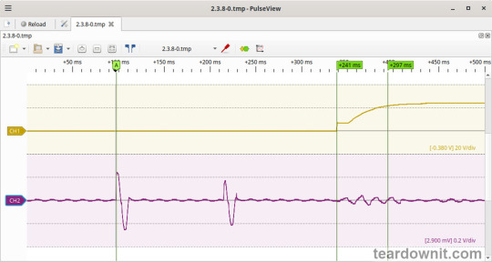
Before the test, the power supply was turned off for at least 5 minutes with the load connected at 100%. The startup waveform at 100% load is shown below (Channel 1: output voltage, Channel 2: input current):

The startup process can be divided into three phases: 1. Input current pulses charging the input capacitors upon connection to the grid, with a peak amplitude of about 3 A, consisting of two portions of one period each. 2. Waiting for the control circuit to start, about 231 ms. 3. (Output Voltage Rise Time) Output voltage rise, 57 ms. 4. (Turn On Delay Time) The total time to reach operational mode from power-on is 288 ms.
(Output Voltage Overshoot) The startup process is aperiodic with no overshoot.
Startup at 0% load
Before the test, the power supply was turned off for at least 5 minutes with the load connected at 100%, then the load was disconnected, and the unit was turned on. The startup waveform at 0% load is shown below:
The startup process consists of three phases: 1. Input capacitors charging upon connection to the grid, with a peak amplitude of about 2.6 A, consisting of two portions of one period each. 2. Waiting for the control circuit to start, about 241 ms. 3. (Output Voltage Rise Time) Converter startup, output voltage rise, and transition to operational mode, 56 ms. (Turn On Delay Time) The total time to reach operational mode from power-on is 297 ms.
(Output Voltage Overshoot) The startup process is aperiodic with no overshoot.
Shutdown Characteristics
The shutdown process was tested at 100% load with nominal input voltage at the moment of shutdown. The shutdown waveform is shown below:

The shutdown process can be divided into two phases: 1. (Shut Down Hold Up Time) The unit continues operating, powered by the charge stored in the input capacitors, until their voltage drops to a critical level at which maintaining the output voltage is no longer possible. This phase lasts for 26 ms. 2. (Output Voltage Fall Time) Output voltage decline, converter stop, and acceleration of the voltage drop. This phase lasts for 25 ms.
(Output Voltage Undershoot) The shutdown process is aperiodic, with no undershoot.
Current amplitude at 100% load prior to shutdown was 2.8 A.
Output voltage ripple
At 100% load:
low-frequency ripple of about 10-12 mVp-p at twice the grid frequency, and around 4 kHz with a ripple of 13-15 mVp-p.

At the converter frequency, ripple is approximately 25 mVp-p, with noise at 120 mVp-p.

At 75% load:
low-frequency ripple of about 10 mVp-p at twice the grid frequency and around 12 mVp-p at approximately 4 kHz.

Converter frequency ripple is about 20 mVp-p, with noise at 100 mVp-p.

At 50% load:
low-frequency ripple of about 10 mVp-p at twice the grid frequency and around 15 mVp-p at approximately 4 kHz.

Converter frequency ripple is about 20 mVp-p, with noise at 100 mVp-p.

At 10% load:
low-frequency ripple of about 3-5 mVp-p.

Converter frequency ripple is about 20 mVp-p, with noise at 100 mVp-p.

At 0% load:
The input current was measured with a multimeter at 60 mA. (Power Consumption) Input current in this mode is primarily reactive in nature; thus, the power consumption value measured with handy instruments can't be correct. The input filter has two capacitors, according to the diagram.
At 0% load, low-frequency ripple is hardly distinguishable from the noise, about 3 mVp-p.

Converter frequency ripple is masked by noise around 100 mVp-p.

Dynamic characteristics
Dynamic characteristics were assessed in a mode that switches between 50% and 100% load. The oscillogram below illustrates the process:

It is evident that the unit's response to step-load changes is aperiodic, with the magnitude of the response to load changes being approximately 100 mV p-p.
Overload protection
The manufacturer specifies overload protection with a constant current limiting type, which was confirmed during testing. When overloaded or the output terminals are shorted, the unit enters current limiting mode and automatically recovers after the fault is removed.
The output current at which the limit is triggered is 22 A.
Input safety assessment
(Input Discharge) The input circuit discharge time constant was measured upon disconnection from the grid, with a value of 0.245 s. This means that when operating on a 120V grid, the time required for the input circuits to discharge to safe levels (<42 V) is 0.39 s:

Important: This result applies only to the tested unit and was obtained exclusively for research purposes. It cannot, under any circumstances, be considered a guarantee of safety.

The ground leakage current was measured at 73µA.
Thermal behavior
No significant heating of components was observed during no-load operation. Thermograms were taken at three power levels—80%, 90%, and 100%—with and without the top cover. The thermograms show that the most thermally loaded components of the unit are the NTC inrush current limiters (4), which stand out from the other components. At 80% load, the NTC temperature is 175.6°F (80°C, with a 53°C rise above ambient temperature); at 90% load, it reaches 192.1°F (89°C, with a 62°C rise); and at 100% load, it reaches 203.9°F (95.5°C, with a 68.5°C rise).
The second hottest component, after the NTC, is a resistor, 25 degrees cooler.
80% load


90% load


100% load


Conclusions
The ERPF-400-24 generally exhibits low noise and ripple, and it maintains good accuracy in sustaining the output voltage. The unit has decent dynamic characteristics, responding to pulsating loads without overshoot.
On the startup waveform (see oscillograms), there is an N-shaped section where, after the initial rise in output voltage, a partial drop occurs, followed by another rise and stabilization at the nominal level. This behavior could potentially cause issues when powering up digital devices that require initialization.
The build quality is good. However, the compound is applied somewhat poorly, with notable imperfections and several gaps. Unfortunately, these gaps affect components with increased hygroscopicity, particularly the wire-wound inductances of the output and input noise filters. Despite the manufacturer's claim of “protecting the internal electronic components from rain splash and dust,” this unit should not be used without additional water ingress protection.
According to the specifications, the unit is designed for operation under conditions of "Cooling by free air convection" and "-22F ~ +140°C (Refer to output load derating curve)." The tested unit indeed remains safe up to 100% load during continuous operation. The presence of a temperature sensor on the rectifier diodes adds extra assurance of safety.
Important: The results and conclusions presented apply only to the tested unit and were obtained solely for research purposes. Under no circumstances should they be used to assess all devices of this type.
0 notes
Text
The Role of Electroplating in Electronics: Why It Matters
Electronics form the backbone of modern technology, powering everything from smartphones to advanced medical devices. Behind the sleek exterior of these gadgets lies a critical process that ensures their efficiency, durability, and functionality: electroplating. Electroplating services in Riyadh have become integral to the electronics industry, offering unparalleled quality and precision.
What is Electroplating?
Electroplating is a process that involves coating a material, usually metal, with a thin layer of another metal using an electric current. This enhances the properties of the base material, such as corrosion resistance, conductivity, and aesthetic appeal. In electronics, electroplating plays a pivotal role in ensuring devices perform optimally under various conditions.
Why Electroplating is Essential in Electronics
Enhanced Conductivity Electronics rely on efficient electrical conductivity to function effectively. Electroplating with metals like gold, silver, or copper improves the conductivity of components such as connectors, circuit boards, and terminals. This ensures seamless transmission of electrical signals, which is vital for high-performance devices.
Corrosion Resistance Corrosion can compromise the integrity of electronic components, leading to malfunctions or failures. Electroplating services in Riyadh offer solutions to prevent this by applying protective metal coatings. For instance, nickel or chromium plating creates a barrier against environmental factors, extending the lifespan of electronic devices.
Improved Solderability For electronic assembly, soldering is a crucial step. Electroplated components exhibit better solderability, making the assembly process smoother and more reliable. This is especially important in high-tech industries such as aerospace and telecommunications.
Aesthetic Finishes Electroplating adds a polished finish to electronic components, enhancing their appearance. This is particularly beneficial for consumer electronics, where aesthetics can influence market appeal.
Cost-Effective Manufacturing Electroplating allows manufacturers to use cost-effective base metals while achieving high-quality surface properties. This reduces overall production costs without compromising on performance.

Applications of Electroplating in Electronics
Electroplating is indispensable in various electronic applications, including:
Printed Circuit Boards (PCBs): Electroplating ensures PCBs are robust, conductive, and long-lasting.
Connectors and Terminals: These components benefit from improved conductivity and corrosion resistance.
Semiconductors: Electroplating enhances the efficiency and reliability of semiconductor devices.
Battery Contacts: High-quality electroplating ensures stable and efficient power flow in batteries.
Electroplating Trends in Riyadh
With Riyadh emerging as a hub for advanced manufacturing and technology, the demand for electroplating services is on the rise. The city's electroplating industry is adapting to global trends, including:
Eco-Friendly Processes: Sustainable plating methods are gaining popularity to reduce environmental impact.
Nanotechnology Integration: Advanced techniques are being used to achieve ultra-thin, precise coatings.
Customization: Tailored solutions are available for industries with unique requirements, such as automotive and aerospace.
Why Choose Arab Arts Metal?
When it comes to electroplating services in Riyadh, Arab Arts Metal stands out as the premier choice. With years of expertise in delivering top-notch metal finishing solutions, they combine innovation with precision to meet the diverse needs of the electronics industry. Their commitment to quality, sustainability, and customer satisfaction has earned them a reputation as the go-to provider for both electroplating services in Riyadh and metal finish in Riyadh.
Whether you need reliable coatings for electronic components or customized solutions for unique projects, Arab Arts Metal ensures excellence in every aspect of their service. Transform your electronics with the best electroplating solutions Riyadh has to offer.
#Electroplating services in Riyadh#Electroplating suppliers in Riyadh#Nickel electroplating#Gold electroplating#Copper electroplating#Silver electroplating#Bronze electroplating#Corrosion resistant coating#Luxury goods electroplating#Jewelry electroplating services#Electroplating for electronic products#Electroplating Sofa furniture#Metal finish in Riyadh#Antique metal finish#Industrial metal coating#Architectural metal finishes
0 notes
Text

Introduction to the difference between HDI board and ordinary PCB
HDI board (High Density Interconnector), that is, high-density interconnect board, is a circuit board with a relatively high line distribution density using micro-blind buried hole technology. HDI board has inner and outer layers, and then uses drilling, in-hole metallization and other processes to connect the internal layers of each layer.
HDI board is generally manufactured by lamination. The more times of lamination, the higher the technical level of the board. Ordinary HDI board is basically 1-time lamination, and high-end HDI uses 2 or more times of lamination technology, and also uses advanced PCB technologies such as stacking holes, electroplating filling holes, and laser direct drilling.
When the density of PCB increases to more than eight layers, the cost of manufacturing with HDI will be lower than the traditional complex pressing process. HDI board is conducive to the use of advanced assembly technology, and its electrical performance and signal accuracy are higher than traditional PCB. In addition, HDI boards have better improvements in radio frequency interference, electromagnetic wave interference, electrostatic discharge, heat conduction, etc.
Electronic products are constantly developing towards high density and high precision. The so-called "high" not only improves the performance of the machine, but also reduces the size of the machine. High-density integration (HDI) technology can make the terminal product design more miniaturized while meeting higher standards of electronic performance and efficiency. Currently, many popular electronic products, such as mobile phones, digital (cameras), laptops, automotive electronics, etc., use HDI boards. With the upgrading of electronic products and market demand, the development of HDI boards will be very rapid.
Introduction to ordinary PCB
PCB (Printed Circuit Board), the Chinese name is printed circuit board, also known as printed circuit board, is an important electronic component, a support for electronic components, and a carrier for electrical connections of electronic components. Because it is made using electronic printing technology, it is called a "printed" circuit board.
Its main function is to avoid manual wiring errors due to the consistency of similar printed boards after electronic equipment adopts printed boards, and can realize automatic insertion or mounting, automatic soldering, and automatic detection of electronic components, ensuring the quality of electronic equipment, improving labor productivity, reducing costs, and facilitating maintenance.
HDI board is a high-density interconnection circuit board. The boards that are electroplated with blind holes and then pressed again are all HDI boards, which are divided into first-order, second-order, third-order, fourth-order, and fifth-order HDI. For example, the motherboard of iPhone 6 is a fifth-order HDI.
Simple buried holes are not necessarily HDI.
How to distinguish between first-order, second-order, and third-order HDI PCBs
The first-order is relatively simple, and the process and technology are easy to control.
The second-order is troublesome. One is the alignment problem, and the other is the problem of punching and copper plating. There are many designs for the second order. One is that the positions of each order are staggered. When the adjacent layer needs to be connected, it is connected through wires in the middle layer. The method is equivalent to two first-order HDIs.
The second is that two first-order holes overlap and achieve the second order by superposition. The processing is similar to two first-order holes, but there are many process points that need to be specially controlled, which is what is mentioned above.
The third is to drill directly from the outer layer to the third layer (or N-2 layer). The process is very different from the previous one, and the difficulty of drilling is also greater.
For the third order, the second order is analogous.
Ordinary PCB boards are mainly FR-4, which is made of epoxy resin and electronic grade glass cloth. Generally, traditional HDI uses adhesive copper foil on the outermost surface. Because laser drilling cannot penetrate glass cloth, adhesive copper foil without glass fiber is generally used, but the current high-energy laser drilling machine can already penetrate 1180 glass cloth. In this way, there is no difference from ordinary materials.
Email us Cynthia<[email protected]> if you are interested in PCB and PCBA service.
0 notes
Text
Application of FETMX6ULL-C Embedded Board in Energy Consumption Monitoring Gateway Products
1. Product Background
The energy consumption monitoring and management system relies on information technologies such as computer networks, wireless communication, and metering collection. This system targets energy mediums such as electricity and water, establishing an energy consumption monitoring center for enterprises, industrial parks, and other energy-consuming units. It enables real-time collection, measurement, and analytical calculation of electricity and water usage, reflecting dynamic data changes and storing historical data for querying, thus achieving digital, networked, and visualized energy and energy-saving management. It helps factory managers understand energy costs, manages control in real time, improves management efficiency, reduces operating costs, and achieves scientific energy use and energy conservation.
Energy consumption monitoring systems have wide applications, including hospitals, residential communities, schools, industrial factories, office buildings, and commercial complexes.

2. Product Features
The energy consumption monitoring system consists of three components: the metering layer, information management layer, and application management layer. The metering terminals include electricity, water, and gas meters, while the gateway collects data from these meters. The system provides statistical analysis, presenting intuitive data visualization to management staff, allowing them to understand real energy consumption data, automatically analyze high energy consumption points, and provide energy-saving solutions for refined management.
Functions of the Energy Consumption Monitoring System
Real-time Monitoring: Continuously monitors the usage of all users within the system, providing real-time data feedback on energy consumption.
Data Analysis: Detailed recording and analysis of electrical usage in each circuit, displayed in tabular format, with the ability to switch to bar charts, line graphs, and other intuitive formats for comparison.
Data Statistics: Offers comprehensive classified and detailed energy consumption statistics reports, allowing users to print daily, monthly, seasonal, and annual electricity consumption statistics at any time.
Fault Alarm: The system issues voice alerts when there is an unexpected change in electricity load, with alarm messages sent to relevant personnel via SMS.
Automatic Energy-saving Report Generation: Staff can review real energy consumption data for public buildings, automatically analyze high energy points, and propose energy-saving solutions for refined building management.
3. Product Design Challenges
Hardware Compatibility and Standardization: The energy consumption monitoring gateway needs to connect multiple types of sensors and metering devices from various manufacturers, using different communication protocols and data formats. Therefore, the gateway’s hardware design must consider broad compatibility and standardized interfaces for seamless device connections.
Stability and Reliability: The monitoring gateway operates 24/7, requiring high stability and reliability in hardware design, including the selection of high-quality components, proper heat dissipation design, and effective fault detection and recovery mechanisms.
Scalability and Maintainability: As technology advances and demands increase, the monitoring gateway may need to expand its functionality or interfaces. Therefore, hardware design must account for future scalability and ensure easy addition of new functions or devices. Good maintainability is essential for quick recovery in case of issues.
Power Consumption and Cost: Since the gateway typically runs continuously, power consumption is a critical factor. Hardware design needs to optimize for lower power usage while reducing costs without sacrificing performance, including the selection of low-power components, optimizing power management, and implementing energy-saving strategies.
4. Implementation Scheme

In response to the aforementioned design challenges, the FETMX6ULL-C embedded boards from Forlinx is proposed as the solution for the energy consumption monitoring gateway. Based on the NXP i.MX6ULL processor and featuring a low-power ARM Cortex-A7 architecture with a speed of up to 800MHz, the FETMX6ULL-C SoM boasts the following characteristics and advantages:
Extensive Interface Compatibility: It natively integrates numerous interfaces including 2x Ethernet, 2x CAN, 8x UART, and 2x USB, allowing it to connect various types of sensors and metering devices with both wired and wireless connectivity, ensuring excellent compatibility and rich functionality for easy expansion with new sensors or devices.
High Stability and Reliability: The FETMX6ULL-C SoM is meticulously designed for high stability and reliability. Its compact size and extensive stability testing by Forlinx ensure it operates reliably in various environments, meeting the requirements for 24/7 monitoring.
Low Power Consumption and Cost-effectiveness: As a low-power processor, the ARM Cortex-A7 architecture contributes to reducing the overall power consumption of the monitoring gateway. Additionally, the competitive pricing of the FETMX6ULL-C SoM makes the entire solution cost-effective.
Ease of Maintenance: Its compact design saves hardware space while allowing for easy disassembly and replacement, enhancing maintainability.
In summary, the energy consumption monitoring gateway solution based on the FETMX6ULL-C Sytem on Module effectively addresses design challenges regarding data acquisition and processing, hardware compatibility and standardization, stability and reliability, security, power consumption and cost, as well as scalability and maintainability. The features of this SoM make it an ideal choice for constructing an efficient, stable, and secure energy consumption monitoring gateway.
more info here:
#FETMX6ULLC#EnergyConsumptionMonitoring#EmbeddedBoard#EnergyManagement#TechInnovation#LowPowerConsumption
0 notes