#RF environment simulation
Explore tagged Tumblr posts
Visit Tumblr Blog
Explore Tumblr blogs with no restrictions, modern design and the best experience.
Last Seen Tumblr Blogs


Fun Fact
BuzzFeed published a report claiming that Tumblr was utilized as a distribution channel for Russian agents to influence American voting habits during the 2016 presidential election in Feb 2018.
Text

A Signal Processing Company in Defense and Aerospace
#Scenario Simulation#Modelling & Simulation#Signal Processing company in Hyderabad#Radar & EW Sensor Testing#Digital Signal Processing#Ansys STK AGI#Telemetry Receivers Manufacturers in hyderabad#radar target echo simulator#Digital Telemtry Receiver#EW Emitter simulator#Target simulator radar in hyderabad#Radar signal generator in hyderabad#Electronic warfare#sar simulator Hyderabad (synthetic aperture radar )#RF environment simulation#ELINT#comint#sigint simulator#THREAT simulator in hyderabad#Aerospace Signal processing company#Best Signal processing company in Hyderabad#Radar signal processing companies in india#Defense Equipment manufacturing companies#Communication systems IP in hyderabad#CRTK Applications#Telemetry manufacturers from Hyderabad#Digital Telemetry Transmitter#Radar Toolkit for Labview
0 notes
Text
Backlog Report. Another month has come and gone. Surprisingly, I only have one singular game to talk about this time around.

Harvestella
This game had the unfortunate start of being announced when the Switch was already being flooded with farming simulators, so a fair amount of people wrote it off by virtue of over saturation. Those that were more interested in it mostly looked forward to it as “Final Fantasy Meets Stardew Valley.” However that comparison is mostly because people don’t play RPGs or Farm Sims, so it’s really just the first example they can list off the top of their heads. I feel like “Rune Factory x NieR x Etrian Odyssey” is a much more accurate comparison.
I’ve played a fair amount of Rune Factory, but it’s never really been an obsession for me. I’m not too deeply motivated to keep farming and greeting villagers daily for their own sake. I prefer more meat and density to my games than wide sandboxes. To that end, Harvestella fit my tastes to a tee, as it places a much higher focus on narrative compared to RF. It has a very unique take on fantasy/sci-fi fusion, and doesn’t take too long to set up its mysteries and hooks. I’m a sucker for ‘Seemingly medieval world swerves hard into science fiction’ type of stories.
As for presentation, it’s absolutely gorgeous. The environments are varied, appropriately themed, and bursting with color and personality. (Except for the places where they don’t, but that’s no purpose.)
Here are a few screenshots to illustrate:


However, there is one problem with the presentation: No Voice Acted Dialogue. Not every game needs voice acting, mind you. It’s just as much a consideration as a capped frame rate, or a pixelated art style, or cel shading. Not every game will run at 120FPS at 2160p resolution, or use Star-studded industry legends in its cast. However Harvestella is odd in that the playable characters do have voice acting, but only in battles. It hampers the cutscenes a bit because the models rely on reusable animations a lot, and without any kind of snappy voices, cutscenes can feel stiff. There’s also the shock of taking a character into battle and Wow Brakka sounds exactly Nothing like what I was reading him. It’s just odd to me because more than enough games at least use a ‘character is [blank] emotion’ type of sound bytes as extra character-specific punctuation marks. They had enough budget to give all their characters battle lines, but couldn’t extend that to include an ‘AriaShockedGasp.mp4”?
The gameplay is a little bit basic. It’s not particularly innovative in its farm sim or job-changi action rpg halves, but it is very solid, with a sizable amount of customization and a satisfying loop of rewards. Hell, there were moments where I shunted story progress entirely just to do all the sidequests I could. The bosses in particular are some highlights to me, as the unique Break system makes each and every one of them a puzzle in how to maximize damage, and when to press your advantages.
In summary, Harvestella by no means reinvents the wheel. It does, however, provide a smooth and fun ride while it lasts. It has a demo on the eShop, I highly recommend you play that and see if it hooks you.
EDIT: Oh yeah, I forgot to mention: the music kicks ass so hard.
20 notes
·
View notes
Text

ROKAF F-4E Phantom Fires Live AIM-7M Sparrow Missile
March 15, 2024 Military Aviation
ROKAF F-4E
A ROKAF F-4E fires an AIM-7M Sparrow. (Image credit: ROKAF)
The last South Korean F-4Es took part in a live firing exercise that saw one Phantom fire an AIM-7M Sparrow Air-to-Air Missile.
Between Mar. 11 and 15, 2024, the Republic of Korea Air Force (ROKAF) conducted live air-to-air and air-to-ground firing training that involved about 40 aircraft of all types, including the F-35A, F-15K, KF-16, F-16, FA-50, and F-4E, as well as U.S. F-16s.
The exercise saw the aircraft tasked with the interception of low-flying cruise missiles launched by the enemy and then with precision air strikes on the origin of the enemy’s firepower: a scenario that simulated the possible escalation of the long standing crisis between South and North Korea.
When the “air-to-air missile live-fire training target”, acting as an enemy cruise missile, was launched, the F-15K, F-35A, FA-50, KF-16, F-16, and F-4E each launched air-to-air missiles to hit the target. The F-35A fired the AIM-9X so as the F-15K fired; the KF-16 fired the AIM-9L and the AIM-120B air-to-air missiles; the F-16 employed the AIM-120B; the FA-50 used the AIM-9L whereas the F-4E fired an old AIM-7M air-to-air missile.
After the enemy launched long-range artillery, ROKAF F-15K, KF-16, and F-16 jets launched air-to-ground missiles and dropped PGMs against the enemy launch sites: the F-15K used the AGM-84H air-to-ground missile and the GBU-31/38 JDAMs; the KF-16 fired the AGM-65G Maverick, the SPICE-2000 air-to-ground bomb as well as the GBU-31/38s; the F-16s dropped the GBU-31; the FA-50 fired the AGM-65G.
The video below shows the South Korean fighters employ a wide array of weapons during the drills. Remarkable, is the segment showing the Phantom firing an AIM-7M, the latest variant of the radar-guided, air-to-air missile Sparrow introduced in 1982 and featuring improved reliability and performance over earlier models (dating back to the mid 1970s) at low altitudes and in electronic countermeasures environments.
youtube
The F-4Es are about to be retired from active service after a 47-year career within ROKAF: the first of 94 Phantoms were inducted into active service in 1977. The service also operated the F-4D and RF-4C which have already been retired, respectively in 2010 and 2014. Both the F-4E and the F-5 fleets will be replaced with F-35A Lightning II, FA-50 Golden Eagle and KF-21 Boramae combat aircraft.
The ROKAF F-4Es are based Suwon Air Base located about 20 miles to the south of Seoul. Suwon is the homebase of the 10th Fighter Wing, the parent unit to the 153rd Fighter Squadron, flying the F-4E Phantom.
Only a dozen F-4Es and about 20 F-5s were still in service at Suwon AB last year.
About David Cenciotti
David Cenciotti is a journalist based in Rome, Italy. He is the Founder and Editor of “The Aviationist”, one of the world’s most famous and read military aviation blogs. Since 1996, he has written for major worldwide magazines, including Air Forces Monthly, Combat Aircraft, and many others, covering aviation, defense, war, industry, intelligence, crime and cyberwar. He has reported from the U.S., Europe, Australia and Syria, and flown several combat planes with different air forces. He is a former 2nd Lt. of the Italian Air Force, a private pilot and a graduate in Computer Engineering. He has written five books and contributed to many more ones
7 notes
·
View notes
Text
RF Chambers | EMC Anechoic Chambers | Anechoic and Acoustic Testing Solutions | dmcrf

RF Anechoic Chambers are specialized shielded environments designed to eliminate electromagnetic and acoustic interference, ensuring accurate testing for industries like telecommunications, automotive, aerospace, and defense. These chambers come in various types, including EMC Anechoic Chambers, Acoustic Chambers, Fully Anechoic Acoustic Chambers, Hemi-Anechoic Acoustic Chambers, and Anechoic Test Boxes, each serving unique testing needs.
In this blog, we explore how these chambers work, their applications, and why they are essential for reliable RF and acoustic measurements.
What Are Anechoic Chambers?
Anechoic chambers are enclosed spaces lined with RF-absorbent or sound-absorbent materials to minimize reflections. They provide a regulated atmosphere devoid of outside noise and electromagnetic interference, which makes them perfect for:
EMC/EMI Testing – Ensuring electronic devices comply with regulatory standards.
Antenna & Radar Testing – Measuring radiation patterns without interference.
Acoustic Testing – Evaluating sound absorption and noise levels.
Types of Anechoic Chambers
1. EMC Anechoic Chambers
These chambers are optimized for Electromagnetic Compatibility (EMC) testing, ensuring devices operate without interfering with other electronics. They are widely used in automotive, military, and consumer electronics industries.
2. Acoustic Chambers
Designed for soundproof testing, these chambers measure noise levels, speaker performance, and material acoustics. They are essential for audio equipment manufacturers and research labs.
3. Fully Anechoic Acoustic Chamber
A fully anechoic chamber absorbs all sound reflections, creating a free-field environment for precise acoustic measurements. Used in microphone calibration, speaker testing, and noise reduction studies.
4. Hemi-Anechoic Acoustic Chamber
This hybrid design features anechoic walls and ceiling but a reflective floor, simulating real-world conditions. Common in automotive NVH (Noise, Vibration, and Harshness) testing and industrial noise analysis.
5. Anechoic Test Box
A compact, cost-effective solution for small-scale RF and acoustic testing, ideal for R&D labs and product development teams needing quick, controlled measurements.
Key Applications of RF Anechoic Chambers
Wireless Communication – Testing 5G, Wi-Fi, and IoT devices.
Automotive Industry – EMC compliance and in-car noise analysis.
Radar cross-section and avionics testing in aerospace and defense.
Consumer Electronics – Ensuring smartphones and wearables meet RF and acoustic standards.
Medical Devices – Validating EMI performance in sensitive equipment.
Why Choose DMCRF Anechoic Chambers?
At DMCRF, we provide custom-designed anechoic chambers tailored to your testing requirements. Our solutions feature:
High-performance RF and acoustic absorption materials.
Compliance with international standards (FCC, CE, MIL-STD).
Expert engineering support for optimal chamber design.
For companies that need accurate electromagnetic and acoustic testing, RF Anechoic Chambers are essential. Whether you need an EMC Anechoic Chamber for compliance or an Acoustic Chamber for noise analysis, choosing the right type ensures accurate and repeatable results.
Looking for a reliable anechoic chamber solution? Visit DMCRF today to explore our range of Fully Anechoic, Hemi-Anechoic, and Anechoic Test Boxes!
Contact Us:
Phone No : +1 (613) 915 5533
Website : https://www.dmcrf.com/
0 notes
Text
ASC-i's Advanced RF Test Capabilities: Ensuring Peak Performance for Your RF PCB Designs
As an industry-leading RF PCB manufacturer, ASC-i is dedicated to providing high-performance, high-quality solutions for a wide range of applications, including wireless communication, automotive radar, medical devices, and IoT systems. When it comes to RF PCBs, ensuring the reliability and functionality of the circuits is paramount. With our advanced RF test capabilities, we ensure that every PCB we produce meets the rigorous demands of the RF industry, delivering optimal performance across all environments and conditions.

The Importance of RF Testing for High-Quality PCB Manufacturing
Radio Frequency (RF) signals are critical for modern communication systems, and even the smallest flaw in the design or manufacturing of an RF PCB can lead to signal loss, interference, or even complete failure. This is why thorough RF testing is essential at every stage of PCB production. At ASC-i, we recognize that precise testing ensures the signal integrity, performance, and durability of the final product. Our RF testing services are designed to identify potential issues early, ensuring that your designs perform at their best before they are integrated into end-use products.
As a trusted RF PCB manufacturer, ASC-i provides comprehensive testing solutions that guarantee each RF PCB we create meets the highest industry standards. Whether you're developing high-frequency communication systems or specialized RF devices, we have the expertise and tools to ensure your products meet exacting specifications.
ASC-i’s Advanced RF Test Capabilities
Our RF test capabilities are built to cover every essential aspect of RF performance, ensuring that your RF PCBs operate reliably and efficiently. Our testing process focuses on key parameters such as signal integrity, impedance matching, thermal stability, power handling, and electromagnetic compatibility. Here’s an overview of our comprehensive RF testing services:
S-Parameter Testing: S-parameters, or scattering parameters, measure the reflection and transmission characteristics of RF circuits. By using high-precision network analyzers, ASC-i tests the insertion loss, return loss, and signal integrity of the RF PCB. This allows us to ensure that the board exhibits minimal signal degradation and high performance under real-world conditions.
Impedance Matching Tests: One of the most critical aspects of RF circuit performance is impedance matching. Proper impedance ensures that the signal is transmitted without reflection or loss. We perform detailed impedance testing across PCB traces, vias, and components to ensure that the impedance is optimized, guaranteeing smooth and efficient signal transmission.
RF Power Handling Testing: RF PCBs often need to handle high power levels, especially in demanding applications like wireless communication, radar, and broadcast systems. We test the power-handling capacity of your PCB to ensure that it can withstand high power inputs without compromising performance or causing thermal issues.
Thermal Performance Testing: RF circuits generate heat, and without proper heat management, thermal buildup can lead to degradation in signal quality or even failure of components. ASC-i conducts comprehensive thermal tests to evaluate how effectively the RF PCB dissipates heat and performs under varying temperature conditions.
Environmental and Aging Tests: To simulate the real-world conditions your RF PCB will face over time, we perform aging and environmental tests that assess how the board handles temperature fluctuations, humidity, vibration, and other environmental factors. This ensures that the RF PCB is durable and can withstand long-term use.
Electromagnetic Interference (EMI) Testing: EMI can significantly disrupt the performance of RF circuits. Our EMI testing ensures that your PCB meets electromagnetic compatibility standards, minimizing the risk of interference with nearby components and ensuring that the device operates smoothly in its intended environment.
Custom RF Testing Solutions for Every Need
At ASC-i, we know that each project is unique. Whether you’re designing a wireless communication system, automotive radar unit, or medical RF device, our team of engineers is ready to customize our testing solutions to meet the specific needs of your design. We work closely with you to understand the requirements of your project and develop a tailored testing plan that addresses all relevant performance factors.
By providing tailored testing services, we ensure that your RF PCBs will meet the precise criteria for your application, ensuring flawless performance across different environments and use cases.
Why Choose ASC-i as Your RF PCB Manufacturer?
Expertise and Experience: With years of experience in designing and manufacturing RF PCBs, ASC-i brings invaluable expertise to every project. Our engineers are well-versed in RF design principles and testing methods, allowing us to deliver high-quality, high-performance RF PCBs for a wide range of applications.
State-of-the-Art Testing Equipment: ASC-i uses the latest testing technologies and equipment to ensure the accuracy and precision of our testing processes. Our RF testing labs are equipped with advanced tools such as network analyzers, spectrum analyzers, thermal chambers, and more to ensure that each PCB is tested to the highest standards.
Comprehensive Testing Services: From signal integrity to thermal and environmental testing, ASC-i provides a full spectrum of RF test services. Our rigorous testing process ensures that each PCB performs optimally in its intended application, providing a reliable solution for every project.
Customization: Every RF PCB design has unique needs. ASC-i offers customized RF testing solutions that can be tailored to meet the specific parameters of your design. We take a collaborative approach to understand the requirements of your project and offer flexible testing services to address your needs.
Quality Assurance: At ASC-i, we prioritize quality in every stage of the manufacturing and testing process. Our robust testing procedures help identify and address any potential issues early, ensuring that your RF PCB meets the highest standards of reliability, durability, and performance.
Timely and Cost-Effective Solutions: We understand the importance of meeting deadlines in the fast-paced world of electronics. ASC-i offers quick turnaround times without compromising quality, allowing you to meet your project timelines while keeping costs under control. Our streamlined processes ensure that you receive competitive pricing for top-tier testing and manufacturing services.
Conclusion
ASC-i is your trusted partner for RF PCB manufacturing and testing services. Our advanced RF test capabilities, coupled with our expertise in RF design and production, allow us to deliver high-quality RF PCBs that perform reliably in the most demanding applications. Whether you’re developing a new wireless communication device, automotive radar system, or medical equipment, ASC-i’s comprehensive RF testing ensures that your PCB will meet the highest standards of performance, reliability, and durability.
Partner with ASC-i today and experience the difference our advanced RF testing capabilities can make for your RF PCB designs. We’re here to help you achieve success by delivering top-quality, high-performance solutions that meet the challenges of today’s technology-driven world. Contact us to learn more about our RF PCB manufacturing and testing services.
0 notes
Text
Wireless Power Transmission Market 2032: Is a Global Energy Transformation Underway
TheWireless Power Transmission Market Size was valued at USD 14.14 Billion in 2023 and is expected to reach USD 39.54 Billion by 2032 and grow at a CAGR of 12.1% over the forecast period 2024-2032.
Wireless Power Transmission Market is gaining widespread traction as the demand for cable-free energy transfer grows across industries including consumer electronics, automotive, healthcare, and industrial automation. The shift toward cordless environments is being driven by advancements in resonant inductive coupling, RF technologies, and laser-based systems.
U.S. leading innovations in automotive and consumer electronics sectors are fueling rapid adoption of wireless power solutions
Wireless Power Transmission Market continues to expand as manufacturers prioritize convenience, mobility, and sustainability. As the global push for efficient energy transfer gains ground, companies are investing in scalable and high-efficiency wireless charging solutions designed to enhance user experience and reduce dependency on physical connectors.
Get Sample Copy of This Report: https://www.snsinsider.com/sample-request/6610
Market Keyplayers:
WiTricity Corporation (WiTricity Halo, WiCAD Simulation Software)
Qualcomm (Qualcomm Halo, Qualcomm WiPower)
Leggett and Platt (Qi-compatible wireless Charging Pads, Helios Wireless Power System)
Energizer (Energizer Wireless Charging Pad, Energizer Qi Charger Stand)
Plugless Power Inc. (Plugless L2 EV Charger, Plugless Power Wireless Charging System)
Texas Instruments (bq500212A Wireless Power Transmitter, bq51013B Wireless Power Receiver)
Murata Manufacturing Co., Ltd. (Wireless Power Supply Module LXWS Series, Power Transmitter Unit LXTX Series)
Unabiz Technology (UnaConnect Wireless Power IoT Module, UnaSensors with Energy Harvesting)
Energous Corporation (WattUp Mid Field Transmitter, WattUp PowerBridge)
Ossia Inc. (Cota Real Wireless Power System, Cota Power Receiver)
VoltServer Inc. (Digital Electricity Line Cards, Digital Electricity Gateway Modules)
Market Analysis
The Wireless Power Transmission Market is evolving rapidly due to growing demand for portable devices, electric vehicles (EVs), and smart medical implants. Businesses are shifting to wireless energy systems to enhance safety, minimize wear-and-tear from physical connections, and support design flexibility. The U.S. market leads with robust R&D funding and tech adoption, while Europe accelerates development through green energy policies and industrial automation strategies.
Market Trends
Surge in EV wireless charging systems
Integration of wireless power in smart homes and offices
Growth in medical devices with wireless energy needs
Development of long-range power delivery technologies
Adoption of magnetic resonance and microwave transmission
Partnerships between OEMs and tech startups
Focus on energy efficiency and eco-friendly design
Market Scope
The market holds vast potential as wireless energy transfer extends across industries, enhancing convenience, design freedom, and system longevity. Key scope areas include:
Wireless charging pads for consumer devices
Dynamic EV charging infrastructure
Remote energy supply for IoT and industrial sensors
Implantable medical devices with continuous power
Military and aerospace applications requiring contactless power
Integration with AI-based energy management systems
Forecast Outlook
Wireless power transmission is entering a new era of innovation, positioning itself as a key enabler of next-gen technologies. With continued investment in R&D, increasing consumer demand for clutter-free environments, and government incentives promoting green tech, the market is expected to evolve rapidly. As major players scale their offerings and infrastructure adapts to support advanced transmission methods, global adoption is set to surge—particularly in North America and Europe where digital ecosystems and sustainability goals align with wireless tech growth.
Access Complete Report: https://www.snsinsider.com/reports/wireless-power-transmission-market-6610
Conclusion
The Wireless Power Transmission Market is reshaping how industries deliver energy—silently, efficiently, and without cords. From powering smart devices in New York to enabling dynamic EV charging in Berlin, wireless technology is no longer futuristic—it's here and expanding fast. Forward-thinking businesses that embrace these innovations will lead the charge toward a more agile, untethered, and energy-smart future.
About Us:
SNS Insider is one of the leading market research and consulting agencies that dominates the market research industry globally. Our company's aim is to give clients the knowledge they require in order to function in changing circumstances. In order to give you current, accurate market data, consumer insights, and opinions so that you can make decisions with confidence, we employ a variety of techniques, including surveys, video talks, and focus groups around the world.
Related Reports:
U.S.A. experiences growing demand for real-time energy monitoring in the Distribution Automation Market
U.S.A drives innovation in wireless gas detection with advanced safety technologies
Contact Us:
Jagney Dave - Vice President of Client Engagement
Phone: +1-315 636 4242 (US) | +44- 20 3290 5010 (UK)
Mail us: [email protected]
#Wireless Power Transmission Market#Wireless Power Transmission Market Scope#Wireless Power Transmission Market Trends
0 notes
Text
Antenna in Package AiP Market Opportunities Rising with Expansion of Millimeter Wave Technology Globally
The Antenna in Package (AiP) market is gaining significant traction as wireless communication technologies become increasingly integrated into compact, high-performance electronic devices. AiP technology incorporates antennas directly into semiconductor packages, enabling advanced radio frequency (RF) performance while saving space. This innovation is particularly relevant in 5G, millimeter-wave (mmWave), automotive radar, satellite communications, and IoT applications.

Market Drivers
One of the primary drivers of the AiP market is the global rollout of 5G technology, which operates at higher frequencies such as mmWave. These frequencies require advanced antenna solutions capable of handling high data rates and low latency. Traditional printed circuit board (PCB) antennas often fall short in terms of integration and performance. AiP offers a more efficient alternative by reducing interconnect losses and supporting beamforming technologies critical for 5G.
Another major factor is the increasing miniaturization of consumer electronics. Smartphones, wearables, and IoT devices demand compact components that deliver excellent performance. AiP technology meets this requirement by integrating the antenna and RF front-end into a single compact module, freeing up space and improving system-level efficiency.
Technological Advancements
Recent advancements in substrate materials, system-in-package (SiP) technologies, and 3D packaging are making AiP solutions more cost-effective and scalable. Low-temperature co-fired ceramic (LTCC) and organic substrates have enabled better thermal and electrical performance. Integration of multiple functions such as filters, power amplifiers, and transceivers within the package has allowed manufacturers to create multi-functional modules tailored for specific end-uses.
In addition, the evolution of advanced simulation tools and design automation has shortened development cycles and reduced costs, making AiP more accessible to a broader range of industries. These advancements have facilitated faster prototyping and more reliable testing environments.
Key Market Segments
The AiP market can be segmented based on frequency band, end-user application, and geography.
By frequency, the market includes sub-6 GHz and mmWave segments, with mmWave seeing higher growth due to its necessity in 5G and automotive radar applications.
By application, the market is divided into consumer electronics, automotive, telecommunications, aerospace and defense, and industrial IoT.
Geographically, North America and Asia-Pacific dominate the AiP landscape, thanks to the presence of major semiconductor companies and 5G infrastructure deployment.
Regional Insights
Asia-Pacific leads the AiP market due to robust electronics manufacturing ecosystems in countries like China, South Korea, Taiwan, and Japan. Government initiatives to boost 5G and smart city projects further support AiP growth in the region. North America, especially the United States, sees significant demand from telecom providers, defense contractors, and autonomous vehicle manufacturers. Europe is also emerging as a key region, driven by automotive and industrial automation applications.
Competitive Landscape
The AiP market is highly competitive, with key players including Qualcomm, ASE Group, Amkor Technology, Murata Manufacturing, TSMC, and MediaTek. These companies are investing in research and development to improve integration, reduce power consumption, and enhance RF performance. Collaborations, joint ventures, and strategic acquisitions are common strategies to gain market share and accelerate product development.
Startups and mid-sized players are also entering the space with niche AiP solutions for IoT and wearable devices, contributing to market dynamism and innovation.
Challenges and Opportunities
Despite its promise, AiP adoption faces several challenges. High design complexity, thermal management issues, and initial manufacturing costs are significant barriers. Additionally, maintaining signal integrity in densely packed modules remains a technical hurdle.
However, opportunities abound. As mmWave adoption expands and edge computing grows in importance, AiP is poised to play a pivotal role in enabling low-latency, high-speed communication across various devices and systems. The trend toward smart cities, connected vehicles, and AR/VR applications also offers long-term growth potential.
Future Outlook
The AiP market is expected to grow at a CAGR exceeding 15% over the next five years, driven by surging demand across multiple industries. Technological advancements, cost optimization, and expanding 5G infrastructure will be key enablers. As device manufacturers strive to balance performance, size, and power efficiency, AiP is likely to become a standard in RF design and packaging.
#AntennaInPackage#AiPMarket#5GTechnology#MillimeterWave#WirelessCommunication#IoTDevices#RFTechnology
0 notes
Text

Step into the world of high-fidelity radar simulation with Digilogic's Synthetic Aperture Radar Environment Simulator (SARES). Designed for realistic SAR image generation, SARES uses a ray-tracing technique to simulate RF signatures of 3D objects with high geometric and radiometric accuracy.
This video showcases how SARES models electromagnetic wave interactions like reflection, scattering and diffraction within a virtual environment. Whether you're analyzing a single object or a complex scene, SARES offers real-time simulations powered by advanced GPU acceleration, allowing users to adjust parameters like object orientation, resolution, incidence angles and material properties on the fly.
Explore how Digilogic Systems SARES supports predefined SAR sensors or custom configurations, giving researchers, defense & aerospace professionals full control over the simulation environment. With a user-friendly interface and support for triangle-based 3D models, it’s built for precision, speed and versatility.
YouTube video link: https://youtu.be/erCyIiuoNMU
SARES webpage link: https://bit.ly/49jqZP1
For enquiries (or) more information, reach out to us.
Phone:
Hyderabad: (+91) 40 4547 4601
Bengaluru: (+91) 80 4975 6034
Website: www.digilogicsystems.com
Email: [email protected]
#aerospace#digilogicsystems#makeinindia#defense#synthetic aperture radar#radar simulation#testautomation#radar#simulation#radar simulator
0 notes
Text
Elmalo, let's commit to that direction. We'll start with a robust Sensor Fusion Layer Prototype that forms the nervous system of Iron Spine, enabling tangible, live data connectivity from the field into the AI's processing core. Below is a detailed technical blueprint that outlines the approach, components, and future integrability with your Empathic AI Core.
1. Hardware Selection
Edge Devices:
Primary Platform: NVIDIA Jetson AGX Xavier or Nano for on-site processing. Their GPU acceleration is perfect for real-time preprocessing and running early fusion algorithms.
Supplementary Controllers: Raspberry Pi Compute Modules or Arduino-based microcontrollers to gather data from specific sensors when cost or miniaturization is critical.
Sensor Modalities:
Environmental Sensors: Radiation detectors, pressure sensors, temperature/humidity sensors—critical for extreme environments (space, deep sea, underground).
Motion & Optical Sensors: Insect-inspired motion sensors, high-resolution cameras, and inertial measurement units (IMUs) to capture detailed movement and orientation.
Acoustic & RF Sensors: Microphones, sonar, and RF sensors for detecting vibrational, audio, or electromagnetic signals.
2. Software Stack and Data Flow Pipeline
Data Ingestion:
Frameworks: Utilize Apache Kafka or Apache NiFi to build a robust, scalable data pipeline that can handle streaming sensor data in real time.
Protocol: MQTT or LoRaWAN can serve as the communication backbone in environments where connectivity is intermittent or bandwidth-constrained.
Data Preprocessing & Filtering:
Edge Analytics: Develop tailored algorithms that run on your edge devices—leveraging NVIDIA’s TensorRT for accelerated inference—to filter raw inputs and perform preliminary sensor fusion.
Fusion Algorithms: Employ Kalman or Particle Filters to synthesize multiple sensor streams into actionable readings.
Data Abstraction Layer:
API Endpoints: Create modular interfaces that transform fused sensor data into abstracted, standardized feeds for higher-level consumption by the AI core later.
Middleware: Consider microservices that handle data routing, error correction, and redundancy mechanisms to ensure data integrity under harsh conditions.
3. Infrastructure Deployment Map
4. Future Hooks for Empathic AI Core Integration
API-Driven Design: The sensor fusion module will produce standardized, real-time data feeds. These endpoints will act as the bridge to plug in your Empathic AI Core whenever you’re ready to evolve the “soul” of Iron Spine.
Modular Data Abstraction: Build abstraction layers that allow easy mapping of raw sensor data into higher-level representations—ideal for feeding into predictive, decision-making models later.
Feedback Mechanisms: Implement logging and event-based triggers from the sensor fusion system to continuously improve both hardware and AI components based on real-world performance and environmental nuance.
5. Roadmap and Next Steps
Design & Prototype:
Define the hardware specifications for edge devices and sensor modules.
Develop a small-scale sensor hub integrating a few key sensor types (e.g., motion + environmental).
Data Pipeline Setup:
Set up your data ingestion framework (e.g., Apache Kafka cluster).
Prototype and evaluate basic preprocessing and fusion algorithms on your chosen edge device.
Field Testing:
Deploy the prototype in a controlled environment similar to your target extremes (e.g., a pressure chamber, simulated low-gravity environment).
Refine data accuracy and real-time performance based on initial feedback.
Integration Preparation:
Build standardized API interfaces for future connection with the Empathic AI Core.
Document system architecture to ensure a smooth handoff between the hardware-first and AI-core teams.
Elmalo, this blueprint establishes a tangible, modular system that grounds Iron Spine in reality. It not only demonstrates your vision but also builds the foundational “nervous system” that your emergent, empathic AI will later use to perceive and interact with its environment.
Does this detailed roadmap align with your vision? Would you like to dive further into any individual section—perhaps starting with hardware specifications, software configuration, or the integration strategy for the future AI core?
0 notes
Text
#Scenario Simulation#Modelling & Simulation#Signal Processing company in Hyderabad#Radar & EW Sensor Testing#Digital Signal Processing#Ansys STK AGI#Telemetry Receivers Manufacturers in hyderabad#radar target echo simulator#Digital Telemtry Receiver#EW Emitter simulator#Target simulator radar in hyderabad#Radar signal generator in hyderabad#Electronic warfare#sar simulator Hyderabad (synthetic aperture radar )#RF environment simulation#ELINT#comint#sigint simulator#THREAT simulator in hyderabad#Aerospace Signal processing company#Best Signal processing company in Hyderabad#Radar signal processing companies in india#Defense Equipment manufacturing companies#Communication systems IP in hyderabad#CRTK Applications#Telemetry manufacturers from Hyderabad#Digital Telemetry Transmitter#Radar Toolkit for Labview
0 notes
Text
Pyramidal vs. Wedge Absorbers: Which Is Best for Your Application?
In the field of electromagnetic compatibility (EMC) testing, antenna measurements, and radar systems, radio frequency (RF) and microwave absorbers are critical components. These absorbers reduce unwanted reflections, absorb stray signals, and create controlled environments for accurate measurements. Among the most widely used absorber shapes are pyramidal and wedge-style designs. While both serve the same general function, their structure, performance characteristics, and ideal use cases differ significantly. Choosing the correct type for your setup can directly impact your testing accuracy and overall efficiency.
This article explores the core differences between pyramidal and wedge absorbers, highlighting their strengths, limitations, and most suitable applications. Whether you're designing a new anechoic chamber or upgrading your current RF shielding system, understanding these distinctions will help you make an informed decision.
Understanding the Role of RF Absorbers
RF and microwave absorbers are materials specifically engineered to absorb electromagnetic waves. By converting RF energy into heat through conductive and resistive processes, these materials reduce signal reflections in test environments. This is especially important in high-frequency applications like EMC testing, radar cross-section measurements, and wireless communication evaluations.
Absorbers typically come in various geometric configurations, each designed to target specific frequency ranges and spatial constraints. Two of the most prevalent shapes are pyramidal and wedge, which differ in design approach but serve similar foundational purposes.
Pyramidal Absorbers: Precision in a Broad Spectrum
Pyramidal absorbers are characterized by their sharp, pointed tips and gradually sloping sides. Constructed from carbon-loaded foam, these structures work by providing a gradual impedance transition between air and absorber material, which significantly reduces signal reflection. Because of their shape, pyramidal absorbers perform exceptionally well over a wide range of frequencies, often from 30 MHz to well above 100 GHz.
One of the most appealing features of pyramidal absorbers is their broadband performance. Their tapering shape makes them effective at absorbing lower-frequency signals, which tend to reflect more in conventional environments. As a result, pyramidal absorbers are commonly used in full-size anechoic chambers, military radar systems, and advanced antenna testing facilities.
They also offer considerable flexibility in size, with height options ranging from a few inches to over three feet. The taller the absorber, the better its performance at lower frequencies. This scalability allows users to tailor the setup based on frequency requirements, budget, and available space.
Advantages of Pyramidal Absorbers
Wide frequency absorption range, including low frequencies
Ideal for high-precision testing environments
Effective in minimizing reflections in 3D test spaces
Scalable sizes to match application needs
Meets demanding performance standards (e.g., NRL 8000 I-III)
Wedge Absorbers: Compact and Directionally Efficient
Wedge absorbers are another widely used type of RF absorber. Unlike the pointed structure of the pyramidal variety, wedge absorbers feature a gradual slope that narrows to a thin edge. This design helps direct incoming electromagnetic waves into the absorber’s depth, where they are dissipated as heat. The tapered profile provides excellent control over signal propagation, particularly for targeted applications.
These absorbers are especially useful in situations where space is limited, or where side-lobe suppression is a priority—such as in antenna pattern testing or radar simulations. Their shape allows them to reduce reflections coming from off-axis angles more efficiently than pyramidal absorbers in certain configurations.
Additionally, wedge absorbers are easier to install in tight or irregularly shaped chambers. Their lower profile makes them suitable for use on sidewalls or ceilings, especially in smaller enclosures where space economy is essential.
Advantages of Wedge Absorbers
More compact design, ideal for limited space
Efficient at suppressing side lobes and indirect reflections
Suitable for controlled, directional test setups
Customizable to specific shape and size requirements
Read more on: https://dbabsorber.com/
1 note
·
View note
Text
Clear signal every time with a perfect 3dB attenuator
Getting a clean and reliable RF signal isn’t just about power — it’s about control. If you’ve ever dealt with signal distortion, mismatch, or unwanted reflections, you already know how important it is to manage signal strength properly. That’s where a 3DB attenuator comes in. It’s a simple tool that solves some of the most frustrating problems in RF setups.
Whether working in a lab, setting up a test bench, or doing field work, using the right attenuator can save time and reduce noise in your system. We offer several high-quality RF attenuators ready to ship fast, so you’re never left waiting.
Here’s why choosing the right attenuator — especially a 3 dB or SMS attenuator — makes a big difference.
Why a 3DB attenuator is the Go-To Choice
A 3DB attenuator is one of the most used types for a reason. It reduces signal power by half, which helps prevent overload in sensitive RF receivers and test equipment. That slight drop in signal can protect your gear and keep everything running smoothly.
Perfect for signal balancing: This is your go-to if you're working on splitting power between paths or keeping signal levels even across multiple devices.
Reliable for testing: Testing gear or simulating loss in real-world conditions? This is an easy fix that saves time and money.
Safe for your equipment: Dropping the signal by 3 dB can be the difference between clean performance and damaging spikes.
We carry attenuators that are made with precision and built for demanding environments. The models come in multiple connector types, including SMA, 2.4mm, and 2.92mm, so you get exactly what you need.
What Makes a SMA Attenuator a Solid Pick
The SMA attenuator stands out for its size, reliability, and solid connection. These are commonly used in high-frequency setups, and we offer models that cover ranges from DC up to 67GHz.
Compact design: SMA connectors are small but durable, great for crowded workspaces or portable kits.
Wide frequency range: Our SMA attenuator options handle everything from basic testing to high-frequency designs, giving you flexibility across projects.
Strong build quality: Brass tri-metal plated bodies offer long-lasting use, especially in lab or field setups with a lot of wear.
You’ll find SMA attenuator models starting at budget-friendly prices without cutting corners on quality.
Why People Keep Coming Back to Us
We care about the little details that make your job easier — fast shipping, quality products, and good support. Whether you're a technician, engineer, or hobbyist, we’ve covered your RF needs.
Same day shipping: Need it fast? We get it. That’s why we ship most products the same day.
RF engineers available: Got a question? Our tech support team includes experienced RF engineers who are easy to reach.
Thousands of ready-to-ship parts: We've stocked our shelves from attenuators to cables and connectors, so you don’t have to wait.
Custom orders welcome: Need something built to spec? No problem — just let us know.
Take the Guesswork Out of RF Projects
Choosing the right attenuator doesn’t have to be complicated. With our easy-to-navigate selection and trusted quality, you can find what you need without second-guessing.
Visit Flexi RF Inc to browse our complete line of attenuators and other RF parts. Whether it’s a 3DB attenuator, a SMA attenuator, or something more specific, we’ve got what you need to keep your signals clean and your projects moving forward.
Source:- Clear signal every time with a perfect 3dB attenuator
1 note
·
View note
Text
Advanced Acoustic Chambers by Diamond Microwave Chambers Ltd
At Diamond Microwave Chambers Ltd, we specialize in engineering silence – the kind of silence that empowers innovation. Our cutting-edge Acoustic Chambers are designed to deliver unmatched performance across a wide range of industries, including automotive, electronics, aerospace, and telecommunication.
Whether you're testing for sound, electromagnetic compatibility, or RF interference, our suite of solutions provides the controlled environments necessary for precise, repeatable, and interference-free measurements.
Our Premium Acoustic Chamber Solutions
1. Anechoic Chambers
Our standard Anechoic Chambers are expertly constructed to absorb sound reflections and external noise. These chambers create an acoustically isolated space that simulates a "free field" condition – perfect for testing speakers, microphones, and other audio equipment.
2. EMC Anechoic Chambers
Electromagnetic Compatibility (EMC) is critical in modern electronics. Our EMC Anechoic Chambers are designed to meet international testing standards such as CISPR 16, MIL-STD, and more. With superior RF shielding and absorbers, these chambers help ensure your products meet compliance with ease.
3. RF Anechoic Chambers
For radio frequency testing, our RF Anechoic Chambers provide the ideal environment. By minimizing reflections and external RF noise, these chambers are indispensable for antenna testing, radar systems, and wireless communication devices.
4. Fully Anechoic Acoustic Chamber
This chamber provides total isolation from both internal and external sound reflections. The Fully Anechoic Acoustic Chamber is perfect for high-precision acoustic testing such as binaural recordings, sound source localization, and psychoacoustic studies.
5. Hemi Anechoic Acoustic Chamber
Need a controlled acoustic environment with a solid floor for testing large equipment or vehicles? Our Hemi Anechoic Acoustic Chambers are built with a reflective ground plane and absorbent walls and ceiling – ideal for testing machinery, engines, and heavy-duty systems.
6. Anechoic Test Box
For compact or on-site testing, our Anechoic Test Boxes offer an efficient solution. These portable units maintain the same precision and noise isolation standards in a compact, flexible format suitable for product development labs and production lines.
Why Choose Diamond Microwave Chambers Ltd?
Customized Designs: Tailored to your testing needs and industry requirements.
Turnkey Solutions: From design to installation and after-sales support.
Compliance Ready: Built to meet global testing standards and regulations.
Innovation-Driven: Backed by a team of acoustic and RF experts with years of experience.
Precision begins in silence. Partner with Diamond Microwave Chambers Ltd and experience the next level of testing excellence.
📞 Contact us today to learn how we can help build your perfect acoustic testing environment.
Call: +1(613) 915 5533
Visit: https://www.dmcrf.com/

#anechoicchambers#acousticanechoicchambers#rfanechoicchambers#antennatestsystems#anechoic test box#rf shielded enclosures#emcanechoicchambers#acoustic anechoic chambers#antenna test systems
0 notes
Text
What Is Satellite Communications Testing? A Complete Guide
What Is Satellite Communications Testing?
Satellite Communications Testing refers to the process of evaluating, verifying, and validating the performance and reliability of satellite communication systems. This includes testing individual components, subsystems, and entire end-to-end communication links, both on the ground and in space.
The purpose of Satellite Communications Testing is to ensure that the satellite and its supporting systems can transmit and receive signals accurately, efficiently, and without interference across various conditions.
Importance of Satellite Communications Testing
Given the high cost of launching and operating satellites, failure is not an option. Testing is therefore crucial for several reasons:
Reliability: To ensure the satellite functions consistently in the harsh environment of space.
Signal Integrity: To maintain high-quality data transmission without loss or distortion.
Regulatory Compliance: To meet the technical standards and frequency allocations defined by global regulatory bodies.
Safety and Security: To protect communication links from potential cyber threats or signal jamming.
Components Involved in Satellite Communications
Before diving into testing methods, it's important to understand the basic components involved in satellite communication:
Satellite Payload – The communication equipment onboard the satellite, including transponders, antennas, and processors.
Ground Station – Facilities on Earth that transmit and receive signals to/from the satellite.
Uplink and Downlink Channels – Frequency bands used for sending signals to and receiving signals from the satellite.
Telemetry, Tracking, and Command (TT&C) – Systems that monitor the health and control the operation of the satellite.
Each of these elements must undergo thorough Satellite Communications Testing.
Types of Satellite Communications Testing
1. RF (Radio Frequency) Testing
One of the core components of Satellite Communications Testing is RF testing, which measures:
Signal strength
Frequency accuracy
Bandwidth utilization
Noise levels
Interference and spurious emissions
RF testing ensures that the satellite can transmit and receive signals within the designated frequency bands effectively.
2. Link Budget Analysis
A link budget calculates the total gain and loss from the transmitter to the receiver. This analysis is critical in Satellite Communications Testing to ensure signal strength is sufficient under different environmental and operational conditions.
3. Antenna Testing
Both satellite and ground-based antennas are tested for:
Gain and beamwidth
Polarization
Pointing accuracy
Radiation patterns
Antenna testing often involves anechoic chambers to simulate free-space environments.
4. Environmental Testing
Satellites must survive extreme conditions in space. Environmental testing includes:
Thermal Vacuum Testing
Vibration and Shock Testing
Electromagnetic Compatibility (EMC) Testing
Radiation Testing
These tests validate the robustness of communication hardware against launch and space environments.
5. Network and Protocol Testing
Satellites today use complex networking protocols. Testing is done to verify:
Routing protocols
Data integrity
Latency and jitter
Error correction mechanisms
This form of Satellite Communications Testing is essential for constellations like Starlink, OneWeb, and Iridium.
6. End-to-End Testing
This simulates the entire communication process from the ground station to the satellite and back. It ensures that the whole system performs under realistic operational conditions.
Tools and Equipment Used in Satellite Communications Testing
Spectrum Analyzers – For RF signal analysis.
Signal Generators – To simulate communication signals.
Network Analyzers – For impedance and signal quality testing.
Antenna Positioners – For evaluating antenna performance.
Channel Emulators – To mimic real-world communication scenarios.
Challenges in Satellite Communications Testing
1. Cost and Complexity
Testing space-grade communication systems is expensive and time-consuming. Each test must simulate real-world scenarios as closely as possible, often requiring custom-built facilities.
2. Latency and Distance
The vast distance between satellites and Earth introduces latency and signal attenuation, complicating test scenarios.
3. Dynamic Environments
Satellites move rapidly relative to Earth, which affects signal behavior. Doppler shift, fading, and handovers between satellites are challenging to simulate accurately.
4. Security and Interference
Ensuring robust encryption and protection against jamming or spoofing is a growing concern, especially for military and government satellites.
Satellite Communications Testing in Different Orbits
LEO (Low Earth Orbit)
Lower latency
Requires frequent handovers
Testing must account for higher Doppler effects
MEO (Medium Earth Orbit)
Used for navigation systems like GPS
Testing focuses on signal precision and reliability
GEO (Geostationary Earth Orbit)
Fixed position relative to Earth
Ideal for continuous coverage
Tests focus on long-duration performance and weather resistance
Standards and Regulations
Satellite Communications Testing must align with guidelines set by:
ITU (International Telecommunication Union)
FCC (Federal Communications Commission)
ECSS (European Cooperation for Space Standardization)
MIL-STD (Military Standards) for defense applications
Compliance ensures safe operation without interfering with other space assets.
Future Trends in Satellite Communications Testing
1. AI and Machine Learning
AI is increasingly used to automate test scenarios, detect anomalies, and optimize network performance.
2. Digital Twins
Simulated environments (digital twins) replicate satellite behavior, allowing for predictive testing and fault diagnosis.
3. Quantum Communications
As space-based quantum communication becomes viable, new testing protocols will be needed to measure entanglement fidelity and quantum bit error rates.
4. Integration with 5G
Satellites will be integral to global 5G infrastructure. Satellite Communications Testing will evolve to ensure seamless handoffs and network compatibility.
Real-World Applications
Military and Defense – Secure, jam-resistant communication for troops and UAVs.
Disaster Recovery – Maintaining communication in areas where terrestrial infrastructure is destroyed.
Remote Internet Access – Bridging the digital divide in underserved regions.
Maritime and Aviation – Continuous coverage for vessels and aircraft worldwide.
Deep Dive: Satellite Communications Testing in the Real World
Now that we've established the critical role of Satellite Communications Testing, it's worth exploring how these practices are applied in various real-world scenarios—from pre-launch validation to in-orbit performance monitoring. The satellite industry is rapidly diversifying, with stakeholders ranging from traditional space agencies and commercial providers to tech startups and universities. Each of these players must engage in tailored testing methodologies based on their mission, orbit selection, payload configuration, and operational goals.
Pre-Launch Testing: The Foundation of Success
Pre-launch testing is the most resource-intensive phase of Satellite Communications Testing. It lays the groundwork for operational success and begins years before a satellite ever leaves the Earth. This phase encompasses:
1. Component-Level Testing
Every circuit board, antenna array, amplifier, and modulator undergoes individual validation. Engineers look for:
Signal-to-noise ratio (SNR)
Linearity of amplifiers
Bit error rate (BER)
Power consumption under load
2. Subsystem Integration Testing
As components are assembled into larger systems, integration tests ensure seamless communication and signal coherence. Subsystem tests may involve:
Testing multiplexing/demultiplexing units
Signal routing through various paths
Thermal impact on performance
3. Payload Testing
The communications payload is the heart of the satellite. It undergoes comprehensive testing using simulated data, signal generators, and even emulated real-world conditions using specialized software.
In-Orbit Testing: The Final Frontier
Once a satellite reaches orbit, in-orbit testing (IOT) is performed to validate all systems under operational conditions. This stage confirms:
Orbital position and pointing accuracy
Antenna beam patterns over coverage areas
Communication link stability
Timing synchronization (especially critical for navigation satellites)
Ground stations collaborate with test engineers and mission operators to verify all these parameters. Software-defined radios (SDRs) are increasingly used for flexible, real-time testing of new waveforms and modulation schemes post-launch.

On-Orbit Testing Tools and Technologies
In recent years, a range of advanced tools have revolutionized Satellite Communications Testing in orbit:
• Software-Defined Payloads
Satellites equipped with SDR-based payloads allow in-flight reconfiguration of frequency bands, modulation techniques, and even test procedures. This flexibility enables:
Adaptive interference mitigation
Dynamic channel allocation
In-situ calibration of RF hardware
• Autonomous Testing and Diagnostics
AI-powered onboard processors now run diagnostic routines in real time. These systems can detect anomalies in signal paths and autonomously alert mission control for corrective action.
• In-Orbit Servicing and Upgrades
Testing also supports satellites undergoing servicing missions, where robotic spacecraft repair, refuel, or upgrade existing systems. Testing routines verify system health before and after such procedures.
Satellite Communications Testing for Constellations
Mega-constellations like Starlink, Kuiper, OneWeb, and Telesat’s Lightspeed introduce a whole new paradigm in Satellite Communications Testing. Instead of testing one or two large satellites, engineers now deal with hundreds or thousands of smaller units.
Key testing challenges for constellations include:
Crosslink Validation: Satellites must communicate with each other via inter-satellite links (ISLs), using lasers or high-frequency RF.
Mass Production Testing: Streamlined testing frameworks ensure quality without bottlenecking production timelines.
Mesh Network Testing: Unlike traditional hub-and-spoke systems, constellations operate in mesh networks. Testing involves validating dynamic routing algorithms, handovers, and load balancing across satellites.
Each satellite within the constellation must be verified both individually and as part of the larger network—emphasizing interoperability, synchronization, and scalability.
Military and Defense Applications
Satellite Communications Testing has especially stringent standards in defense contexts. Secure communications, signal robustness, and low detectability are paramount. The military employs a wide range of testing protocols, including:
1. Jamming Resistance Testing
Simulated electronic warfare environments test satellite systems for resilience to jamming and signal interference.
2. Encryption and Key Management
Secure key distribution is tested both during payload integration and throughout mission duration. Any failure in secure communications could compromise national security.
3. Low Probability of Intercept/Detection (LPI/LPD)
Advanced signal modulation techniques are tested for their ability to reduce the chance of detection or interception by adversaries.
4. Mobile Testing Platforms
Mobile ground stations, aircraft, and naval vessels are used as test platforms to validate connectivity in the field.
Commercial and Civilian Applications
In the commercial sector, Satellite Communications Testing plays a central role in:
• Broadband Internet
Starlink and similar providers rely on high-throughput satellite (HTS) systems. Testing ensures consistent performance in:
Rural and remote environments
High-latency zones
Urban areas with RF congestion
• Aviation Connectivity
Airlines test satellite links for inflight entertainment and cockpit communications. Latency, packet loss, and handoff testing between beams or satellites are especially critical during flight.
• Maritime Applications
Oceangoing vessels depend on satellite comms for navigation, crew communications, and emergency systems. Testing ensures reliable coverage across vast oceanic expanses.
• Emergency and Disaster Response
Organizations like FEMA and the Red Cross deploy portable satellite terminals in disaster-hit zones. These devices are tested for plug-and-play reliability, battery performance, and secure transmission.
Academic and Research Testing
Universities and research institutes also play a major role in pushing the boundaries of Satellite Communications Testing:
CubeSats and NanoSats: Low-cost, small satellites are perfect for testing experimental communication protocols.
Deep Space Communication: Testing extremely long-range signals (e.g., for Mars missions) involves high-precision Doppler tracking and weak-signal processing.
Amateur Radio Satellites (AMSAT): These projects contribute to protocol testing, antenna development, and community education.
Testing Frameworks and Standards
Several formal frameworks guide the Satellite Communications Testing process, including:
• ECSS-E-ST-10C
European Cooperation for Space Standardization’s system engineering standard.
• CCSDS Protocol Standards
The Consultative Committee for Space Data Systems outlines protocols for space data handling, including telemetry and communications.
• MIL-STD-188
A U.S. Department of Defense standard outlining criteria for interoperation and performance of military satellite communication systems.
• ISO/IEC 19794
International standards for biometric and secure communication testing—applied in certain high-security satellite applications.
Compliance with these frameworks ensures interoperability, safety, and performance consistency across global operators.
Software Tools for Satellite Communications Testing
A number of simulation and analysis tools support satellite testing workflows:
STK (Systems Tool Kit) by AGI/Ansys: Simulates orbital mechanics, link budgets, and signal coverage.
MATLAB/Simulink: Widely used for modeling modulation, signal processing, and RF link behavior.
GNU Radio: An open-source toolkit for SDR development and testing.
LabVIEW: Used to automate test equipment and data collection in lab environments.
These tools often integrate with physical instruments like spectrum analyzers, oscilloscopes, and signal generators to create hybrid virtual/physical testbeds.
Satellite Communications Testing and Cybersecurity
As satellite networks become internet-enabled and software-defined, cybersecurity testing has become a critical part of communications validation. This includes:
Penetration Testing: Simulating attacks on ground stations or satellite command links to uncover vulnerabilities.
Firmware Integrity Checks: Ensuring the software onboard is authentic and tamper-proof.
Zero-Trust Architecture Testing: Verifying systems don’t automatically trust any data source, even internally.
In response to increasing space-based threats, agencies like the U.S. Space Force and NATO have begun issuing cybersecurity mandates as part of their satellite comms testing protocols.
Emerging Trends in Satellite Communications Testing
Let’s take a look at some of the most exciting trends shaping the future of Satellite Communications Testing:
1. AI-Driven Predictive Testing
AI algorithms are being trained to identify patterns in testing data, allowing for predictive maintenance and early failure detection.
2. Miniaturized Test Systems
CubeSats and smallsats require compact test equipment that still delivers high accuracy. Innovations in photonics and embedded computing are making this possible.
3. Cloud-Based Test Automation
Ground-based test facilities are moving to the cloud, enabling remote access to test results, simulations, and control systems for teams around the globe.
4. Hybrid Satellite-Terrestrial Testing
With 5G and IoT systems increasingly blending satellite and ground infrastructure, testing must cover multi-domain connectivity. This includes vertical handovers, latency optimization, and network slicing.
Careers in Satellite Communications Testing
If you're interested in entering this dynamic field, here are a few career roles directly involved in Satellite Communications Testing:
RF Test Engineer
Satellite Systems Analyst
Antenna Test Technician
Ground Station Engineer
Satellite Network Architect
Telemetry & Command Specialist
Employers include space agencies (NASA, ESA), defense contractors (Lockheed Martin, Raytheon), telecom companies (SES, Viasat), and NewSpace startups (SpaceX, AST SpaceMobile).
Final Thoughts
Satellite Communications Testing is one of the most technically demanding yet vital areas in the space industry. It serves as the bridge between concept and mission success. From ensuring a satellite’s antennas work in freezing space to validating that internet packets reach a ship in the middle of the Pacific, testing is what keeps the promise of space-based communications alive.
As we move into an era defined by AI-driven constellations, quantum communications, and multi-orbit architectures, the role of Satellite Communications Testing will only become more critical. It's not just about proving that a system works—it's about ensuring it performs reliably, securely, and adaptively in a rapidly evolving environment.
Whether you're a student, engineer, manager, or enthusiast, understanding and appreciating the nuances of Satellite Communications Testing gives you a deeper insight into the invisible backbone of our modern digital world.
0 notes
Text
Wireless Testing Market: Size, Share, Analysis, Forecast, and Growth Trends to 2032 – Regional Trends and Country-Level Analysis

The Wireless Testing Market was valued at USD 15.2 Billion in 2023 and is expected to reach USD 45.0 Billion by 2032, growing at a CAGR of 12.83% from 2024-2032.
The Wireless Testing Market is undergoing rapid transformation, driven by increasing demand for seamless connectivity, advancements in wireless technologies such as 5G and Wi-Fi 6, and the rising integration of IoT across various sectors. As industries evolve toward automation and smart infrastructure, the need for efficient wireless communication systems has surged, pushing enterprises to invest heavily in testing solutions that ensure compliance, performance, and security. This growing dependency on wireless systems across industries like automotive, healthcare, and consumer electronics has positioned wireless testing as a pivotal component in development cycles.
The Wireless Testing Market is also seeing heightened activity from regulatory bodies mandating rigorous certification standards. This has led to a significant uptick in demand for comprehensive testing services and tools. Vendors are innovating their testing methodologies to keep pace with the accelerating development of wireless technologies. As organizations prioritize product reliability and interoperability, wireless testing becomes essential not only for compliance but also for reducing product recalls and enhancing brand trust.
Get Sample Copy of This Report: https://www.snsinsider.com/sample-request/5980
Market Keyplayers:
Keysight Technologies – UXM 5G Wireless Test Platform
Rohde & Schwarz – R&S CMW500 Wideband Radio Communication Tester
Anritsu Corporation – MT8821C Radio Communication Analyzer
Viavi Solutions Inc. – OneAdvisor-800 Wireless Test System
Spirent Communications – Spirent Landslide Wireless Core Network Testing
DEKRA SE – DEKRA Wireless Device Testing Services
Bureau Veritas – Smartworld Wireless Testing Solutions
Intertek Group plc – Intertek Wireless Compliance Testing
TÜV Rheinland – TÜV Rheinland OTA & RF Testing
TÜV SÜD – TÜV SÜD Mobile Device Certification Testing
Eurofins Scientific – Eurofins Wireless Performance Testing
SGS SA – SGS Wireless Network Testing Services
Element Materials Technology – Element RF & Microwave Testing
COMPRION GmbH – COMPRION Network Simulators
Ansys Inc. – Ansys HFSS Wireless Simulation
Market Analysis
The market is driven by the exponential rise in connected devices and the global rollout of next-generation wireless networks. With businesses embracing digital transformation, wireless testing ensures robust and uninterrupted communication across systems and devices. Strategic partnerships and mergers among key players are enhancing market reach and technological capabilities. Testing equipment manufacturers are focusing on multi-device, multi-protocol platforms that provide real-time analytics and simulation environments.
Market Trends
Growing adoption of 5G and Wi-Fi 6/6E driving demand for advanced testing tools
Expansion of IoT devices requiring cross-platform wireless compatibility
Rise in remote working creating demand for stable and secure wireless connectivity
AI and ML integration in testing platforms for predictive and automated testing
Regulatory push for compliance and safety boosting third-party testing services
Market Scope
Smart Mobility Revolution: Automotive industry’s shift to connected and autonomous vehicles increases wireless testing in V2X communication
Healthcare Connectivity: Medical devices with wireless capabilities demand strict testing for patient safety and operational reliability
Consumer Tech Explosion: Surge in wearables, smart home gadgets, and personal devices intensifies testing for seamless user experience
Enterprise-grade Networks: Digital businesses investing in private wireless networks are relying on rigorous testing for cybersecurity and reliability
The scope of the wireless testing market spans multiple high-growth sectors, creating new opportunities for test equipment manufacturers, service providers, and network vendors. With each new innovation in wireless technology, the market expands its reach into areas previously unconnected, offering massive potential for differentiation and profitability.
Market Forecast
The wireless testing market is expected to maintain a strong growth trajectory in the coming years, fueled by the technological race for faster, smarter, and more reliable wireless communication. As innovations in edge computing, IoT, and AI reshape industries, wireless testing will evolve to support complex, real-time, and mission-critical applications. Emerging markets and global digital infrastructure projects will further bolster demand for wireless compliance and performance validation. The future of this market will not only be shaped by new wireless technologies but also by the need for secure, efficient, and resilient networks.
Access Complete Report: https://www.snsinsider.com/reports/wireless-testing-market-5980
Conclusion
The Wireless Testing Market stands at the crossroads of innovation and necessity. As the world becomes increasingly connected, the role of wireless testing will continue to grow, ensuring that the invisible networks we rely on every day are fast, secure, and dependable. For industry leaders, investors, and innovators, this market presents a unique opportunity to drive technological excellence while ensuring user trust. Now is the time to tap into the pulse of wireless progress and lead with precision in a digitally connected future.
About Us:
SNS Insider is one of the leading market research and consulting agencies that dominates the market research industry globally. Our company's aim is to give clients the knowledge they require in order to function in changing circumstances. In order to give you current, accurate market data, consumer insights, and opinions so that you can make decisions with confidence, we employ a variety of techniques, including surveys, video talks, and focus groups around the world.
Contact Us:
Jagney Dave - Vice President of Client Engagement
Phone: +1-315 636 4242 (US) | +44- 20 3290 5010 (UK)
#Wireless Testing Market#Wireless Testing Market Scope#Wireless Testing Market Share#Wireless Testing Market Trends
0 notes
Text
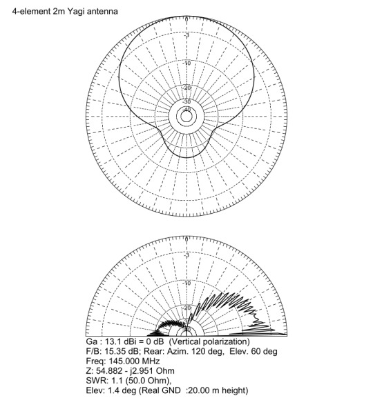
4-Element Yagi antenna for the 2m band
This blog post discusses the engineering design, construction, and performance evaluation of a 4-element Yagi-Uda antenna specifically optimized for the 2-meter amateur radio band, focusing on the frequency range of 144MHz to 145.5MHz. The project was initiated to establish strong and reliable communication with distant VHF repeaters of the RSSL (Radio Society of Sri Lanka), which are located approximately 58km and 96km from my location.

The primary objective was to develop a high-gain, directional antenna with a superior front-to-back ratio. This directionality is essential for maximizing signal capture from the desired repeater while minimizing interference and noise from unwanted directions, ultimately improving the SNR and the quality of the communication link.
VHF communication at these distances typically relies on line-of-sight propagation, making antenna gain a critical factor in overcoming path loss and achieving reliable signal levels.

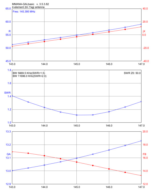
The antenna design was carried out using MMANA-GAL, a well-known and validated software suite based on the Method of Moments (MoM) for antenna analysis. While MoM simulations require significant computational resources, they deliver accurate predictions of antenna performance. This is achieved by breaking down the antenna structure into small segments and solving Maxwell's equations to determine the current distribution. This approach enables precise modeling of antenna impedance, radiation patterns, gain, and front-to-back ratio.
Key design parameters were iteratively optimized within MMANA-GAL to achieve the desired performance:
Target Frequency Band: 144MHz - 145.5MHz, encompassing the primary 2m amateur band frequencies.
Characteristic Impedance: 50Ω, to ensure impedance matching with standard RG-58 coaxial transmission line and transceiver equipment, minimizing reflected power and maximizing power transfer to the antenna.
Front-to-Back Ratio Optimization: Aiming for a high front-to-back ratio to minimize reception from the rear hemisphere, reducing interference and improving signal clarity, especially in noisy RF environments.
SWR Minimization: Achieving a VSWR as close to 1:1 as possible across the target frequency band. Low VSWR indicates efficient impedance matching and minimal power reflection back to the transmitter.
The simulation process involved adjusting the lengths of the elements and the spacing between them for the reflector, driven element, and directors of the Yagi antenna. This antenna operates on the principles of constructive and destructive interference of electromagnetic waves. The reflector, positioned behind the driven element, reflects waves forward, while the directors, located in front of the driven element, help to focus the radiated energy toward the main lobe. This arrangement increases both the forward gain and directivity of the antenna.

The optimized design, after multiple simulation iterations in MMANA-GAL, predicted the following performance metrics:
Simulated Gain: 13.1dBi. This represents a significant gain increase over a dipole antenna (approximately 2.15dBi) and translates to a substantial improvement in signal strength.
Simulated Front-to-Back Ratio: 15.35dB. This indicates that the power radiated in the forward direction is over 15dB stronger than in the backward direction, providing good directivity and rejection of rearward signals.
Simulated Input Impedance: Close to 50Ω across the 144MHz - 145.5 MHz band, ensuring a good match to standard 50Ω transmission lines.
The construction of the antenna focused on durability, lightweight design, weather resistance, and good electrical conductivity, all while keeping costs reasonable. We used 10mm diameter aluminum alloy tubes sourced from Lanka Aluminum. This diameter was selected because it is commonly available at many aluminum stores.
For the boom, we use a rigid 19.05mm (3/4 inch) square aluminum box bar, also sourced from Lanka Aluminum. This material is made from a similar aluminum alloy to ensure structural integrity and to serve as a common ground plane for the parasitic elements. The square profile enhances torsional stiffness compared to a round boom.
To effectively secure the components, we use 10mm ABS element holders. These holders are commonly utilized here to construct VHF/UHF TV antennas. Both the plastic holders and 10mm end caps are sourced from Kumarasinghe Radio.

The Polychrome junction box, measuring 85×85×50 mm and designed for outdoor use, is waterproof with an IP55 rating. This rating indicates that the box provides protection against dust ingress (although some dust may enter, it won’t cause harm) and shields against water jets from any direction. This makes it an essential choice for long-term outdoor deployment, ensuring the critical dipole feedpoint remains protected.
We used corrosion-resistant M3 stainless steel nuts, bolts, and washers to secure all elements and the IP box.
Precise assembly is crucial for achieving the intended performance of a Yagi antenna. All elements, except for the driven dipole, were directly and electrically bonded to the aluminum boom. This is a standard practice for Yagi antennas, as it utilizes the boom as a common ground, simplifying construction. Electrical connections were established using M3 stainless steel bolts that passed through pre-drilled holes in the aluminum tubes and boom, ensuring reliable electrical contact. The element holders provided mechanical support and maintained precise spacing between the elements, as well as a 90° angle with the boom, in accordance with the design specifications from MMANA-GAL.

The IP55 box containing the dipole was securely mounted to the underside of the aluminum boom using M3 stainless steel fasteners. To ensure consistent height with other elements, we used a strip of 10mm acrylic sheet.
Antenna VSWR and input impedance were measured across the frequency range of 144MHz - 145.5MHz using a VNA. The measured SWR of 1.1 at 145.025MHz confirms excellent impedance matching at the desired operating frequency. A Smith chart, generated by the VNA, visually represented the antenna's impedance characteristics throughout the band. It demonstrated that the impedance remained close to the target of 50Ω, indicating a broadband match across the intended operating frequencies.

The antenna was deployed at the designated operating location and oriented towards the target RSSL VHF repeaters. A subjective performance evaluation was conducted by attempting communication with the repeaters at distances of 58km (Yatiyanthota) and 96km (Piduruthalagala).
Reports from repeater users consistently indicated an S9+ signal strength, showing a significant improvement in reception when compared to a baseline mobile whip antenna.
You can find the complete design of this antenna, including all dimensions, in the PDF linked here. The Fusion 360 design file for the antenna is also available here. Additionally, the MMANA-GAL design file (in .mma format) can be downloaded from this link.
0 notes