#Safety Valve Reaction Force Calculations
Text
Unleashing the Potential of Little P.Eng. for ASME B31.3 Process Piping Calculation Services
In the ever-evolving landscape of the process piping industry, ASME B31.3 Process Piping Calculation Services stands as a paramount standard for design, inspection, and construction of process plants. As we delve into the complex world of piping engineering, we encounter Little P.Eng., an innovative engineering consulting firm pioneering the application of these industry standards.
With years of profound expertise and a cutting-edge approach, Little P.Eng. shines as the gold standard in providing ASME B31.3 Process Piping Calculation Services. This article aims to shed light on the instrumental role that Little P.Eng. plays in revolutionizing the field of process piping.
Understanding ASME B31.3 Process Piping Standards:
ASME B31.3, a prominent subsection of the American Society of Mechanical Engineers (ASME) B31 Code for Pressure Piping, is a comprehensive set of guidelines for process piping. It includes various aspects such as materials, fabrication, examination, testing, and much more. Given its criticality, these standards must be implemented with utmost precision and accuracy, an arena where Little P.Eng. truly excels.
Little P.Eng.: Your Reliable Partner for Piping Calculation Services:
As a recognized leader in the engineering consulting sector, Little P.Eng. is fully equipped to handle all facets of ASME B31.3 process piping calculation services. Leveraging the expertise of highly-skilled professionals, the latest technologies, and deep-rooted understanding of ASME standards, Little P.Eng. delivers innovative, accurate, and cost-effective solutions.
Little P.Eng. and Comprehensive Calculation Services:
Little P.Eng.'s range of calculation services spans from pressure design of piping components, flexibility and stress analysis, to support design and selection. Their commitment to precision, comprehensive reports, and prompt delivery, all tied to their deep-rooted understanding of ASME B31.3 standards, ensure that they stay ahead of the competition.
Embracing the Latest Technology:
Little P.Eng. makes optimal use of the latest technologies to provide unmatched ASME B31.3 process piping calculation services. Using state-of-the-art software tools, they simulate, analyze, and validate designs, leading to safe, reliable, and efficient process piping systems.
Customer Satisfaction: Little P.Eng.'s Hallmark:
With a steadfast commitment to customer satisfaction, Little P.Eng. prioritizes its clients' needs at every stage of the project. This results in services that not only adhere to ASME B31.3 standards but also align with the specific requirements of the clients.
Let's delve deeper into the pressure design calculations performed by Little P.Eng. under the ASME B31.3 Process Piping Calculation Services. Here are the key types of pressure design calculations:
Wall Thickness Calculations: One of the most crucial aspects of pressure design calculations involves determining the minimum wall thickness required for pipes to safely contain the pressure. Little P.Eng. uses sophisticated software tools to compute this accurately, factoring in variables like operating pressure, material strength, temperature, and pipe diameter.
Flange Rating Calculations: Little P.Eng. expertly handles the complexity of flange rating calculations, which involve determining the maximum pressure that flanges can handle without leaking. The process considers factors such as temperature, bolting material, gasket type, and flange material.
Branch Connection Calculations: When designing a process piping system, engineers often need to calculate the reinforcements required for branch connections. Little P.Eng. performs these calculations with precision, ensuring the integrity and safety of the piping system.
Expansion Joint Pressure Thrust Calculations: Expansion joints are vital components of process piping systems that accommodate thermal expansion or contraction. Little P.Eng. uses advanced tools to calculate the pressure thrust exerted on these joints, thus ensuring their optimal design.
Safety Valve Reaction Force Calculations: Little P.Eng. also determines the reaction force exerted on safety valves when they open in response to excessive pressure. These calculations are essential for the safe and efficient operation of the process piping system.
Pipe Support Span Calculations: Pipe support span calculations are critical for ensuring that the pipe doesn't sag excessively under its weight and operating conditions. Little P.Eng. performs these calculations meticulously, keeping in mind various factors such as pipe size, material, and temperature.
High-Pressure Piping Design Calculations: For high-pressure piping systems, Little P.Eng. offers specialized calculation services that consider unique challenges such as material selection, joint design, and testing procedures, ensuring the integrity of the system even under extreme pressure conditions.

Conclusion:
The ASME B31.3 Process Piping Calculation Services can be quite challenging to navigate without the assistance of an experienced partner like Little P.Eng. Their meticulous attention to detail, robust understanding of industry standards, and unflinching commitment to quality make them an invaluable asset in the realm of process piping.
Little P.Eng.'s team of expert engineers works tirelessly to stay at the forefront of evolving industry standards, technologies, and market demands, ensuring their clients get the best of what the industry has to offer. With their forward-thinking approach, they not only provide services but also contribute to shaping the future of the process piping industry.
Keywords:
Little P.Eng., ASME B31.3 Process Piping Calculation Services, engineering consulting, process piping industry, process piping standards, pressure design, flexibility and stress analysis, support design and selection, customer satisfaction, Wall Thickness Calculations, Flange Rating Calculations, Branch Connection Calculations, Expansion Joint Pressure Thrust Calculations, Safety Valve Reaction Force Calculations, Pipe Support Span Calculations, High-Pressure Piping Design Calculations.
Tags:
Little P.Eng.
engineering consulting
Expansion Joint Pressure Thrust Calculations
Safety Valve Reaction Force Calculations
High-Pressure Piping Design Calculations
ASME B31.3 Process Piping Calculation Services
process piping industry
process piping standards
pressure design
flexibility and stress analysis
support design and selection
customer satisfaction
Wall Thickness Calculations
Flange Rating Calculations
Branch Connection Calculations
Pipe Support Span Calculations
Engineering Services
Pipe Stress Analysis Services
Piping Design
Located in Calgary, Alberta; Vancouver, BC; Toronto, Ontario; Edmonton, Alberta; Houston Texas; Torrance, California; El Segundo, CA; Manhattan Beach, CA; Concord, CA; We offer our engineering consultancy services across Canada and United States. Meena Rezkallah.
#Little P.Eng.#engineering consulting#Expansion Joint Pressure Thrust Calculations#Safety Valve Reaction Force Calculations#High-Pressure Piping Design Calculations#ASME B31.3 Process Piping Calculation Services#process piping industry#process piping standards#pressure design#flexibility and stress analysis#support design and selection#customer satisfaction#Wall Thickness Calculations#Flange Rating Calculations#Branch Connection Calculations#Pipe Support Span Calculations
0 notes
Text
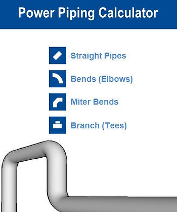
Little P.Eng. for ASME B31.1 Power Piping Calculation Services: A Beacon of Expertise and Innovation
Power piping systems serve as the lifeblood of many industrial operations, providing crucial transportation of fluids under high pressure and temperature. These systems demand high standards of safety, reliability, and efficiency, which are delivered by the American Society of Mechanical Engineers (ASME) B31.1 Power Piping Code. One name stands out in offering these precise and complex ASME B31.1 Power Piping Calculation Services - Little P.Eng.
A leading engineering consulting firm, Little P.Eng., combines experience, innovation, and cutting-edge technology to provide unrivaled solutions for power piping systems. In this article, we examine Little P.Eng.'s impact on ASME B31.1 Power Piping Calculation Services and how they excel in this specialized domain.
Deciphering ASME B31.1 Power Piping Code:
ASME B31.1 Power Piping Code is a robust regulatory framework that stipulates design, fabrication, installation, and testing regulations for power piping systems. With its technical intricacies, this code is an engineer's playbook for ensuring the safety and efficacy of power piping systems, and no one plays this game better than Little P.Eng.
Little P.Eng.: Your Trustworthy Ally for Power Piping Calculations:
In the field of ASME B31.1 power piping calculation services, Little P.Eng. has carved a distinctive niche for itself. Their team of seasoned engineers, with a comprehensive understanding of ASME standards, employ the best practices to provide highly accurate and reliable solutions, making them a trusted ally for all power piping needs.
Little P.Eng.'s Extensive Calculation Services:
Little P.Eng.'s expertise spans a wide spectrum of calculation services. From wall thickness calculations to expansion joint pressure thrust calculations, Little P.Eng.'s solutions are renowned for their precision and adherence to ASME B31.1 standards. The firm's exhaustive understanding of power piping systems equips them to handle complex calculations with ease and precision.
Harnessing the Power of Technology:
At Little P.Eng., the latest technology and software tools are harnessed to ensure their ASME B31.1 Power Piping Calculation Services meet the highest industry standards. By using advanced simulation techniques and design validation, they create power piping systems that are safe, reliable, and efficient.
Prioritizing Client Satisfaction:
Little P.Eng. places a strong emphasis on client satisfaction, ensuring each project is tailored to the specific needs of the client. Their commitment to quality, paired with their industry knowledge, delivers solutions that not only meet ASME B31.1 standards but also align seamlessly with the client's requirements.
let's delve into the specific types of pressure design calculations that Little P.Eng. offers under the ASME B31.1 Power Piping Calculation Services:
Minimum Pipe Wall Thickness Calculations: Ensuring the pipe wall is thick enough to contain the internal pressure is a fundamental aspect of pressure design. Little P.Eng. uses state-of-the-art software to calculate the required wall thickness, considering factors like operating pressure, material strength, temperature, and pipe diameter.
Flange Pressure-Temperature Ratings Calculations: Little P.Eng. adeptly handles the calculation of flange ratings under different temperature and pressure conditions. These calculations are crucial for specifying the appropriate flanges that will ensure a leak-free performance of the power piping system.
Branch Reinforcement Calculations: Branch connections, if not properly reinforced, can be potential weak points in a piping system. Little P.Eng. carries out detailed calculations to determine the necessary reinforcements, ensuring the structural integrity and safety of the piping system.
Expansion Joint Pressure Thrust Calculations: Expansion joints in power piping systems need to withstand the pressure thrust exerted upon them. Little P.Eng. uses sophisticated tools and techniques to accurately calculate this pressure thrust, helping to design expansion joints that can safely absorb these forces.
Safety Valve Reaction Force Calculations: When safety valves open in response to excessive pressure, they exert a reaction force that must be taken into account. Little P.Eng.'s team expertly performs these calculations, ensuring safety valves can operate efficiently and safely.
Pipe Support Load Calculations: The load on pipe supports must be accurately calculated to ensure they can sustain the weight of the pipe, the fluid it carries, and any additional loads due to thermal expansion or other forces. Little P.Eng. performs these calculations meticulously, considering various factors such as pipe size, material, and temperature.
High-Pressure Piping Design Calculations: High-pressure piping systems pose unique design challenges. Little P.Eng. offers specialized calculation services to address these, considering factors such as material selection, joint design, and testing procedures.
Conclusion:
ASME B31.1 Power Piping Calculation Services form the backbone of power piping design, ensuring systems can safely and efficiently transport fluids under high-pressure conditions. Little P.Eng., with its mastery of these calculations and unwavering dedication to quality, stands as a beacon of expertise and innovation in this field.
The team at Little P.Eng. continuously adapts to evolving industry standards and market needs, ensuring their clients receive top-tier, cutting-edge services. Their commitment to using the latest technology and best practices positions them as not just a service provider but as a key contributor in shaping the future of the power piping industry.
Keywords: Minimum Pipe Wall Thickness Calculations, Flange Pressure-Temperature Ratings Calculations, Branch Reinforcement Calculations, Expansion Joint Pressure Thrust Calculations, Safety Valve Reaction Force Calculations, Pipe Support Load Calculations, High-Pressure Piping Design Calculations, ASME B31.1 Power Piping Calculation Services, Little P.Eng., power piping systems, engineering consulting, ASME standards, wall thickness calculations, expansion joint pressure thrust calculations, client satisfaction, technological advancements.
Tags:
Meena Rezkallah
Little P.Eng.
engineering consulting
ASME standards
Expansion Joint Pressure Thrust Calculations
Safety Valve Reaction Force Calculations
High-Pressure Piping Design Calculations
client satisfaction
Minimum Pipe Wall Thickness Calculations
Flange Pressure-Temperature Ratings Calculations
Branch Reinforcement Calculations
Pipe Support Load Calculations
ASME B31.1 Power Piping Calculation Services
power piping systems
wall thickness calculations
expansion joint pressure thrust calculations
technological advancements
Engineering Services
Pipe Stress Analysis Services
Piping Design
Located in Calgary, Alberta; Vancouver, BC; Toronto, Ontario; Edmonton, Alberta; Houston Texas; Torrance, California; El Segundo, CA; Manhattan Beach, CA; Concord, CA; We offer our engineering consultancy services across Canada and United States. Meena Rezkallah.
#Meena Rezkallah#Little P.Eng.#engineering consulting#ASME standards#Expansion Joint Pressure Thrust Calculations#Safety Valve Reaction Force Calculations#High-Pressure Piping Design Calculations#client satisfaction#Minimum Pipe Wall Thickness Calculations#Flange Pressure-Temperature Ratings Calculations#Branch Reinforcement Calculations#Pipe Support Load Calculations#ASME B31.1 Power Piping Calculation Services#power piping systems#wall thickness calculations#expansion joint pressure thrust calculations#technological advancements
0 notes
Video
Pipe Flexibility Analysis / Pipe Stress Analysis Services is a critical component in any piping design. It is mandatory that the critical piping which are operating under high pressure or high temperature services need to be analyzed for flexibility , expansion and load sustaining capabilities. Apart from process and power piping, District cooling systems which employ pre-insulated pipes and piping inside the energy transfer stations need to be analyzed for flexibility and expansion as per API, ASME B31.3, B31.1, B31.8, B31.4, CSA Z662. Meena Development LTD. offers comprehensive service which covers all aspects of Pipe Stress analysis in both industries.
Due to the extensive calculations required, the stress analysis will be carried out with the assistance of computer simulation and modeling software such as CARSAE II.
The stress analysis provides useful design information including the location of any high stress concentrations and bends within the network it also highlights areas requiring attention by way of redesign and or adding additional anchors or hangers to eliminate high stresses in the piping system.
Pipe Stress Analysis for Onshore and off shore Process and Power Piping :
1. Advising on pipeline routing and elevation profile
2. Static load and stress calculations of above ground and underground piping systems
3. Wind load calculation
4. FRP & GRP pipe stress analysis
5. Offshore piping stress analysis
6. Fatigue analysis and cumulative usage report
7. Dynamic analysis and harmonic forces and displacements of piping systems
8. Mode shapes and natural frequency calculations
9. Shock spectrum analysis and independent support motion (earthquake)
10. Force spectrum analysis (liquid hammer, slug flow & relief valve discharge)
11. Model time history analysis
12. Calculation of Spring Stiffness
13. Thrust force of Expansion Bellows
14. Effects of Thermal Loads, Occasional loads such as Hydrostatic Test, Safety Valve's Reaction Force, Seismic Loads, Wind Loads
15. Vibration Analysis Steam Hammer & Water Hammer Sea Wave load spectrum
16. Safety Valve Reaction Force
17. Calculation of Displacement of Terminal point movement due to Thermal, Equipment Foundation Settlement ,Pipe Support Movement, Pipe Support Foundation Settlement
The purpose of the stress analysis in piping systems is to identify the behavior of the pipes, piping components under the potential static loading experienced from the start up to operation. In particular, the stress analysis is undertaken to confirm that stresses produced in the piping system as a result of the temperature difference, pressure and dead weight will comply with the governing codes for such static loads. Moreover, the calculated displacements and restraint (anchors and hangers) loads under these static conditions should comply as well with these governing codes.
Pipe Support Engineering Design:
1. Selection of Pipe Supports
2. Load calculation for Pipe Support
3. Structural design of Pipe Supports
4. Spring Hanger Data Sheets
5. Thrust Block Sizing
6. Plates, Inserts & Loading Drawing (input to Civil)
Because Meena Development LTD. offers an array of multidisciplinary services (Pipe Stress Analysis and Structural Engineering), we can provide pipe stress analysis solutions across a multitude of industries. The listing below indicates a few of Meena Development’s most commonly served industries.
1. Steel and Metals Industry
2. Energy and Power Generation Industry
3. Water and Wastewater Industry
4. Oil & Gas Industry
5. Chemicals and Plastics Industry
6. Pulp & Paper Industry
7. Facility Services
0 notes
Link
In order to properly design a piping system, the engineer must understand both a system's behavior under potential loadings, as well as the regulatory requirements imposed upon it by the governing codes.
A system's behavior can be quantified through the aggregate values of numerous physical parameters, such as accelerations, velocities, displacements, internal forces and moments, stresses, and external reactions developed under applied loads. Allowable values for each of these parameters are set after review of the appropriate failure criteria for the system. System response and failure criteria are dependent on the type of loadings, which can be classified by various distinctions, such as primary vs. secondary, sustained vs. occasional, or static vs. dynamic.
The ASME/ANSIB31 piping codes are the result of approximately 8 decades of work by the American Society of Mechanical Engineers and the American National Standards Institute (formerly American Standards Association) aimed at the codification of design and engineering standards for piping systems. The B31 pressure piping codes (and their successors, such as the ASME Boiler and Pressure Vessel Section III nuclear piping codes) prescribe minimum design, materials, fabrication, assembly, erection, test, and inspection requirements for piping systems intended for use in power, petrochemical/refinery, fuel gas, gas transmission, and nuclear applications.
Due to the extensive calculations required during the analysis of a piping system, this field of engineering provides a natural application for computerized calculations, especially during the last two to three decades. The proliferation of easy-to-use pipe stress software has had a two-fold effect: first, it has taken pipe stress analysis out of the hands of the highly-paid specialists and made it accessible to the engineering generalist, but likewise it has made everyone, even those with inadequate piping backgrounds, capable of turning out official-looking results.
The intention of this course is to provide the appropriate background for engineers entering the world of pipe stress analysis. The course concentrates on the design requirements (particularly from a stress analysis point of view) of the codes, as well as the techniques to be applied in order to satisfy those requirements. Although the course is taught using the CAESAR II Pipe Stress Analysis Software, the skills learned here are directly applicable to any means of pipe stress analysis, whether the engineer uses a competing software program or even manual calculational methods.
Why do we Perform Pipe Stress Analysis?
There are a number of reasons for performing stress analysis on a piping system. A few of these follow:
In order to keep stresses in the pipe and fittings within code allowable levels.
In order to keep nozzle loadings on attached equipment within allowables of manufacturers or recognized standards (NEMA SM23, API 610, API 617, etc.).
In order to keep vessel stresses at piping connections within ASME Section VIII allowable levels.
In order to calculate design loads for sizing supports and restraints.
In order to determine piping displacements for interference checks.
In order to solve dynamic problems in piping, such as those due to mechanical vibration, acoustic vibration, fluid hammer, pulsation, transient flow, and relief valve discharge.
In order to help optimize piping design.
Typical Pipe Stress Documentation
Documentation typically associated with stress analysis problems consists of the stress isometric, the stress analysis input echo, and the stress analysis results output. Examples of these documents are shown in Figures 1-1 through 1-5 on subsequent pages.
The stress isometric (Figure 1-1) is a sketch, drawn in an isometric coordinate system, which gives the viewer a rough 3-D idea of the piping system. The stress isometric often summarizes the piping design data, as gathered from other documents, such as the line list, piping specification, piping drawing, Appendix A (Figure 1-2) of the applicable piping code, etc. Design data typically required in order to do pipe stress analysis consists of pipe materials and sizes; operating parameters, such as temperature, pressure, and fluid contents; code stress allowables; and loading parameters, such as insulation weight, external equipment movements, and wind and earthquake criteria.
Points of interest on the stress isometric are identified by node points. Node points are required at any location where it is necessary to provide information to, or obtain information from, the pipe stress software. Typically, node points are located as required in order to:
define geometry (system start, end, direction changes, intersection, etc.)
note changes in operating conditions (system start, isolation or pressure reduction valves, etc.)
define element stiffness parameters (changes in pipe cross section or material, rigid elements, or expansion joints)
designate boundary conditions (restraints and imposed displacements)
specify mass points (for refinement of dynamic model)
note loading conditions (insulation weight, imposed forces, response spectra, earthquake g-factors, wind exposure, snow, etc.)
retrieve information from the stress analysis (stresses at piping mid spans, displacements at wall penetrations, etc.)
The input echo (Figure 1-3) provides more detailed information on the system, and is meant to be used by the pipe stress engineer in conjunction with the stress isometric.
The analysis output provides results, such as displacements, internal forces and moments, stresses, and restraint loadings at each node point of the pipe, acting under the specified loading conditions. CAESAR II provides results in either graphic or text format; Figures 1-4 and 1-5 present stress and displacement results graphically. The output also provides a code check calculation for the appropriate piping code, from which the analyst can determine which locations are over stressed.
What are these Stresses?
The stresses calculated are not necessarily real stresses (such as could be measured by a strain gauge, for example), but are rather "code" stresses. Code stress calculations are based upon specific equations, which are the result of 8 decades of compromise and simplification. The calculations reflect:
Inclusion or exclusion of piping loads, based upon convenience of calculation or selected failure. In fact the result may not even represent an absolute stress value, but rather a RANGE of values.
Loading type — these are segregated, and analyzed separately, as though they occur in isolation, even though they actually are present simultaneously.
Magnification, due to local fitting configuration, which may in reality reflect a decrease in fatigue strength, rather than an increase in actual stress.
Code committee tradition — every code is a result of a different set of concerns and compromises, and therefore may appear to be on a different branch of the evolutionary ladder. Because of this, every code gives different results when calculating stresses.
A summary of significant dates in the history of the development of the piping codes is presented below:
1915 - Power Piping Society provides the first national code for pressure piping.
1926 - The American Standards Association initiates project B31 to govern pressure piping. 1955 - Markl publishes his paper "Piping Flexibility Analysis", introducing piping analysis methods based on the "stress range". 1957 - First computerized analysis of piping systems. 1968 - Congress enacts the Natural Pipeline Safety Act, establishing CFR192, which will in time replace B31.8 for gas pipeline transportation. 1969 - Introduction of ANSI B31.7 code for Nuclear power plant piping. 1971 - Introduction of ASME Section III for Nuclear power plant piping. 1974 - Winter Addenda B31.1 moves away from the separation of bending and torsional moment terms in the stress calculations and alters the intensification factor for moments on the branch leg of intersections. 1978 - ANSI B31.7 is withdrawn. 1987 - Welding Research Council Bulletin 330 recommends changes to the B31.1, B31.3, and ASME III Class 2 and 3 piping codes.
Index:
Pipe Stress Analysis Notes
1.0 Introduction to Pipe Stress Analysis
1.1 Theory and Development of Pipe Stress Requirements
1.1.1 Basic Stress Concepts
1.1.2 3-D State of Stress in the Pipe Wall
1.1.3 Failure Theories
1.1.4 Maximum Stress Intensity Criterion
1.2 Fatigue Failure
1.2.1 Fatigue Basics
1.2.2 Fatigue Curves
1.2.3 Effect of Fatigue on Piping
1.2.4 Cyclic Reduction Factor
1.2.5 Effect of Sustained Loads on Fatigue Strength
1.3 Stress Intensification Factors
1.4 Welding Research Council Bulletin
1.5 Code Compliance
1.5.1 Primary vs. Secondary Loads
1.5.2 Code Stress Equations
1.5.3 B31.1 Power Piping
1.5.4 B31.3 Chemical Plant and Petroleum Refinery Piping
1.5.5 ASME Section III, Subsections NC & ND (Nuclear Class 2 & 3)
1.5.6 B31.4 Fuel Gas Piping
1.5.7 B31.8 Gas Transmission and Distribution Piping Code
1.5.8 Canadian Z183/Z184 Oil/Gas Pipeline Systems
1.5.9 RCC-MC
1.5.10 Stoomwezen
1.5.11 Special Considerations of Code Compliance
1.5.12 Evaluation of Multiple Expansion Range Cases
Check
Piping Engineering Services
Engineering Company
Piping Engineering Company
Tags:
Introduction to Pipe Stress Analysis
CAESAR II
Pipe Stress Analysis Notes
•
Piping Stress Analysis
2,424 views
Engineering Consulting Services Alberta
Engineering Consulting Services British Columbia
Engineering Consulting Services Saskatchewan
Engineering Consulting Services Ontario
Engineering Consulting Services Middle East (Arabian Gulf)
Engineering Services
0 notes
Link
Piping Design
Piping Stress Analysis
Engineering Services
(Pipe Stress Analysis, Pipe Support & Structural Analysis) Engineering Services across Canada (Ontario, Alberta, British Columbia & Saskatchewan)
September 9, 2020
P.Eng.
Meena Rezkallah
Meena Development LTD. Engineering Services Division is a specialized engineering services provider in the plant design industry catering to certain key and challenging engineering design services. It provides world class services to our clients across Canada and USA with our highly professional teams and by following best industry practices and internationally formulated standards and by adhering to international Society Codes such as ASME/API/BS/CSA Codes for Design/Analysis verification and validation. Meena Development LTD. provides these Plant Engineering services worldwide from facilities in Alberta, Ontario, British Columbia and Saskatchewan. With its leadership position in engineering solutions to Oil and Gas industries in north america for two decade, Meena Development LTD. Engineering Services Division provides the following Services:
OIL & GAS
Meena Development LTD. Offers its engineering services to Upstream, midstream and Downstream Projects to Oil & Gas Industries.
Pipe Stress Analysis
Pipe Support Design
3D Plant Modeling
Hydraulic Calculation
Surge Analysis
Static Equipment Analysis
SKID DESIGN
A skid system is any process implement, operational device or system that can help a customer save time and money, or increase flexibility by assembling a group of modular pieces together as a single unit.
Pipe Stress Analysis
Pipe Support Design
Complete SKID 3D Modeling
Hydraulic Calculation
Pressure Vessel Analysis
DISTRICT COOLING
District cooling is the centralized production and distribution of cooling energy delivered via an underground insulated pipeline to cool the indoor air of the buildings within a district.
Pipe Stress Analysis
Pipe Support Design
3D Modeling of Pump & ETS Area
Hydraulic Calculation
Surge Analysis
Static Equipment Analysis
Thermal Storage Tank Design
FIRE PROTECTION
Fire Protection system is very essential to the any industrial safety requirements.
Pipe Stress Analysis
Pipe Support Design
3D Modeling of Fire
Protection system
Hydraulic Calculation
Surge Analysis
SEWAGE TREATMENT
Sewage treatment is the process of removing contaminants from industrial wastewater to produce environmentally safe treated wastewater.
Offering:
Pipe Stress Analysis
Pipe Support Design
3D STP Plant Modeling
Hydraulic Calculation
Surge Analysis
Pipe Stress Analysis
Pipe Flexibility is a critical component in any piping design. It is mandatory that the critical piping which are operating under high pressure or high temperature services need to be analyzed for flexibility, expansion and load sustaining capabilities. Meena Development LTD. offers comprehensive service which covers all aspects of Pipe Stress analysis for various industries. What we do – Static load and stress calculations of above ground and underground piping systems.
Wind load calculation.
FRP & GRP pipe stress analysis.
Offshore piping stress analysis.
Fatigue analysis and cumulative usage report.
Dynamic analysis and harmonic forces and displacements of piping systems.
Mode shapes and natural frequency calculations.
Shock spectrum analysis and independent support motion (earthquake).
Force spectrum analysis (liquid hammer, slug flow & relief valve discharge).
Model time history analysis.
Calculation of Spring Stiffness.
Thrust force of Expansion Bellows.
Effects of Thermal Loads.
Vibration Analysis.
Steam Hammer & Water Hammer.
Sea Wave load spectrum.
Safety Valve Reaction Force.
Pipe Support & Structural Analysis
Meena Developmet LTD. offers services in Structural engineering / analysis of structural components used in refineries, chemical plants, power plants, pharmaceutical plants, food processing plants and other processing facilities. Typical structural engineering / analysis which are provided are as follows:
Structural Analysis:
Structural engineering calculations per AISC (American Institute of Steel Construction), IS, ACI, AASHTO, BS, UBC & API to design, analyze and check the load carrying capacities of various structural components (vessel internal components, rectangular ducts with stiffeners, pipe racks, pipe supports, beams, columns, structural connections etc.).
Calculations of minimum retirement thickness based on structural engineering considerations (also known as structural Min. ‘T’ to avoid jeopardizing the structural stability of pressure equipment (Pressure vessels, Heat exchangers, tanks and piping).
Structural Analysis and Design of special structures and non-pressure parts (e.g. platforms, ladders, clips and other attachments) attached to various parts of Pressure Vessels and Heat Exchangers. These calculations may include hand calculations or customized MathCAD calculations.
Structural stability analysis (e.g. nonlinear buckling analysis) to make sure that the structure / mechanical component will not buckle for the given design loading.
Pipe Support Design:
Selection of Pipe Supports
Load calculation for Pipe Support
Structural design of Pipe Supports
Spring Hanger Data Sheets
Thrust Block Sizing
Plates, Inserts & Loading Drawing (input to Civil)
Located in Calgary Alberta, We offer our Piping Engineering Services, Skid Design Services and Structural Engineering Services across Canada. To get our Piping Stress Analysis Services, please contact our Engineering company.
Our structural Engineers / piping stress engineers have a bachelor's and Master's degree in mechanical / structural engineering and province licence (P.Eng.) in Alberta, Saskatchewan, British Columbia and Ontario. We review, validate, certify and stamp piping and structural packages. Also check Industries We Serve.
TAGS:
Pipe Stress Analysis Services
Pipe Support
Structural Analysis Services
Engineering Consulting Services Alberta
Engineering Consulting Services Saskatchewan
Engineering Consulting Services British Columbia
Engineering Consulting Services Ontario
0 notes
Link
.0 Introduction to Pipe Stress Analysis
March 11, 2020
P.Eng.
Meena Rezkallah
In order to properly design a piping system, the engineer must understand both a system's behavior under potential loadings, as well as the regulatory requirements imposed upon it by the governing codes.
A system's behavior can be quantified through the aggregate values of numerous physical parameters, such as accelerations, velocities, displacements, internal forces and moments, stresses, and external reactions developed under applied loads. Allowable values for each of these parameters are set after review of the appropriate failure criteria for the system. System response and failure criteria are dependent on the type of loadings, which can be classified by various distinctions, such as primary vs. secondary, sustained vs. occasional, or static vs. dynamic.
The ASME/ANSIB31 piping codes are the result of approximately 8 decades of work by the American Society of Mechanical Engineers and the American National Standards Institute (formerly American Standards Association) aimed at the codification of design and engineering standards for piping systems. The B31 pressure piping codes (and their successors, such as the ASME Boiler and Pressure Vessel Section III nuclear piping codes) prescribe minimum design, materials, fabrication, assembly, erection, test, and inspection requirements for piping systems intended for use in power, petrochemical/refinery, fuel gas, gas transmission, and nuclear applications.
Due to the extensive calculations required during the analysis of a piping system, this field of engineering provides a natural application for computerized calculations, especially during the last two to three decades. The proliferation of easy-to-use pipe stress software has had a two-fold effect: first, it has taken pipe stress analysis out of the hands of the highly-paid specialists and made it accessible to the engineering generalist, but likewise it has made everyone, even those with inadequate piping backgrounds, capable of turning out official-looking results.
The intention of this course is to provide the appropriate background for engineers entering the world of pipe stress analysis. The course concentrates on the design requirements (particularly from a stress analysis point of view) of the codes, as well as the techniques to be applied in order to satisfy those requirements. Although the course is taught using the CAESAR II Pipe Stress Analysis Software, the skills learned here are directly applicable to any means of pipe stress analysis, whether the engineer uses a competing software program or even manual calculational methods.
Why do we Perform Pipe Stress Analysis?
There are a number of reasons for performing stress analysis on a piping system. A few of
these follow:
In order to keep stresses in the pipe and fittings within code allowable levels.
In order to keep nozzle loadings on attached equipment within allowables of manufacturers or recognized standards (NEMA SM23, API 610, API 617, etc.).
In order to keep vessel stresses at piping connections within ASME Section VIII allowable levels.
In order to calculate design loads for sizing supports and restraints.
In order to determine piping displacements for interference checks.
In order to solve dynamic problems in piping, such as those due to mechanical vibration, acoustic vibration, fluid hammer, pulsation, transient flow, and relief valve discharge.
In order to help optimize piping design.
Typical Pipe Stress Documentation
Documentation typically associated with stress analysis problems consists of the stress isometric, the stress analysis input echo, and the stress analysis results output. Examples of these documents are shown in Figures 1-1 through 1-5 on subsequent pages.
The stress isometric (Figure 1-1) is a sketch, drawn in an isometric coordinate system, which gives the viewer a rough 3-D idea of the piping system. The stress isometric often summarizes the piping design data, as gathered from other documents, such as the line list, piping specification, piping drawing, Appendix A (Figure 1-2) of the applicable piping code, etc. Design data typically required in order to do pipe stress analysis consists of pipe materials and sizes; operating parameters, such as temperature, pressure, and fluid contents; code stress allowables; and loading parameters, such as insulation weight, external equipment movements, and wind and earthquake criteria.
Points of interest on the stress isometric are identified by node points. Node points are required at any location where it is necessary to provide information to, or obtain information from, the pipe stress software. Typically, node points are located as required in order to:
define geometry (system start, end, direction changes, intersection, etc.)
note changes in operating conditions (system start, isolation or pressure reduction valves, etc.)
define element stiffness parameters (changes in pipe cross section or material, rigid elements, or expansion joints)
designate boundary conditions (restraints and imposed displacements)
specify mass points (for refinement of dynamic model)
note loading conditions (insulation weight, imposed forces, response spectra, earthquake g-factors, wind exposure, snow, etc.)
retrieve information from the stress analysis (stresses at piping mid spans, displacements at wall penetrations, etc.)
The input echo (Figure 1-3) provides more detailed information on the system, and is meant to be used by the pipe stress engineer in conjunction with the stress isometric.
The analysis output provides results, such as displacements, internal forces and moments, stresses, and restraint loadings at each node point of the pipe, acting under the specified loading conditions. CAESAR II provides results in either graphic or text format; Figures 1-4 and 1-5 present stress and displacement results graphically. The output also provides a code check calculation for the appropriate piping code, from which the analyst can determine which locations are over stressed.
What are these Stresses?
The stresses calculated are not necessarily real stresses (such as could be measured by a
strain gauge, for example), but are rather "code" stresses. Code stress calculations are based
upon specific equations, which are the result of 8 decades of compromise and simplification.
The calculations reflect:
Inclusion or exclusion of piping loads, based upon convenience of calculation or selected failure. In fact the result may not even represent an absolute stress value, but rather a RANGE of values.
Loading type — these are segregated, and analyzed separately, as though they occur in isolation, even though they actually are present simultaneously.
Magnification, due to local fitting configuration, which may in reality reflect a decrease in fatigue strength, rather than an increase in actual stress.
Code committee tradition — every code is a result of a different set of concerns and compromises, and therefore may appear to be on a different branch of the evolutionary ladder. Because of this, every code gives different results when calculating stresses.
A summary of significant dates in the history of the development of the piping codes is
presented below:
1915 - Power Piping Society provides the first national code for pressure piping.
1926 - The American Standards Association initiates project B31 to govern pressure piping.
1955 - Markl publishes his paper "Piping Flexibility Analysis", introducing piping analysis methods based on the "stress range".
1957 - First computerized analysis of piping systems.
1968 - Congress enacts the Natural Pipeline Safety Act, establishing CFR192, which will in time replace B31.8 for gas pipeline transportation.
1969 - Introduction of ANSI B31.7 code for Nuclear power plant piping.
1971 - Introduction of ASME Section III for Nuclear power plant piping.
1974 - Winter Addenda B31.1 moves away from the separation of bending and torsional moment terms in the stress calculations and alters the intensification factor for moments on the branch leg of intersections.
1978 - ANSI B31.7 is withdrawn.
1987 - Welding Research Council Bulletin 330 recommends changes to the B31.1, B31.3, and ASME III Class 2 and 3 piping codes.
Index:
Pipe Stress Analysis Notes
1.0 Introduction to Pipe Stress Analysis
1.1 Theory and Development of Pipe Stress Requirements
1.1.1 Basic Stress Concepts
1.1.2 3-D State of Stress in the Pipe Wall
1.1.3 Failure Theories
1.1.4 Maximum Stress Intensity Criterion
1.2 Fatigue Failure
1.2.1 Fatigue Basics
1.2.2 Fatigue Curves
1.2.3 Effect of Fatigue on Piping
1.2.4 Cyclic Reduction Factor
1.2.5 Effect of Sustained Loads on Fatigue Strength
1.3 Stress Intensification Factors
1.4 Welding Research Council Bulletin
1.5 Code Compliance
1.5.1 Primary vs. Secondary Loads
1.5.2 Code Stress Equations
1.5.3 B31.1 Power Piping
1.5.4 B31.3 Chemical Plant and Petroleum Refinery Piping
1.5.5 ASME Section III, Subsections NC & ND (Nuclear Class 2 & 3)
1.5.6 B31.4 Fuel Gas Piping
1.5.7 B31.8 Gas Transmission and Distribution Piping Code
1.5.8 Canadian Z183/Z184 Oil/Gas Pipeline Systems
1.5.9 RCC-MC
1.5.10 Stoomwezen
1.5.11 Special Considerations of Code Compliance
1.5.12 Evaluation of Multiple Expansion Range Cases
Piping Engineering Services
TAGS:
Introduction to Pipe Stress Analysis
caesar ii
0 notes
Link
Types of Pipe Loading Conditions
May 23, 2018
P.Eng.
Meena Rezkallah
Piping loads are classified into three types: sustained loads, occasional loads, and expansion loads. These three types of loads and the corresponding analysis will be discussed in this section in detail.
Method of analysis. The piping stress analysis to be performed could be a simplified analysis or a computerized analysis. The choice of the proper analysis depends on the pipe size and the piping code. For small (nominal diameter 2 in and under) pipe except nuclear Class 1 pipe, a cookbook-type, simplified analysis could be performed. For nuclear Class 1 piping, since the requirements are more stringent, a computerized analysis is required. A detailed description of a cookbook-type, simplified analysis and a brief description of a computerized analysis are given in the section that follows, ‘‘Methods of Analysis.’’ Generally, before computerized analysis is performed, pipe supports may be located using the cookbook method.
Sustained Load: Pressure
Internal pressure in piping usually induces stresses in the pipe wall rather than loads on the pipe supports. This is because pressure forces are balanced by tension in the pipe wall, resulting in zero pipe support loadings. A discussion of unbalanced forces in the pipe created by pressure waves during fluid transients is given in the subsection ‘‘Dynamic Loads.’’
Pressure Stress.
The longitudinal stress developed in the pipe due to internal pressure can be calculated as follows:
The second equation gives pressure stress in terms of the ratio of pipe flow area to metal area. It also provides a more accurate result. Both equations are acceptable to the code.
Expansion Joint.
In piping design, elbows, bends, and pipe expansion loops normally provide adequate flexibility for piping thermal expansion and contraction. However, in some cases this flexibility may not be adequate. As a solution, expansion joints may be used to absorb the expansion and contraction of pipe.
In general, expansion joints are used for the following applications:
Where thermal movements would induce excessive stress in normal piping arrangements
Where space is inadequate
Where reactions transmitted by pipe supports or anchors create large loads on supporting structures
Where reactions to equipment terminals are in excess of allowables
When expansion joints are used in piping, the pressure forces can no longer be balanced by tension in the pipe wall, and the pressure forces will be resisted by pipe supports and anchors.
There are many types of expansion joints available, ranging from a piece of rubber hose to metal bellows. The metal bellows expansion joint is most commonly used for power or process piping. Figure B4.6 shows the various components of a bellows expansion joint.
Expansion joints do not have the capability to transmit large pressure forces. Restraints are usually installed on both sides of the expansion joint to prevent the pressure force from pulling the joint apart. The pressure force developed in the expansion joint is equal to the internal pressure times the maximum cross-sectional area over which it is applied. Since an expansion joint increases the flexibility of a piping system, the flexibility (spring rate) of the expansion joint should be incorporated in the piping stress analysis.
Sustained Load: Weight
The total design weight load of pipe supports includes the weight of the pipe,
fittings, insulation, fluid in pipe, piping components such as valves, valve operators,
flanges, and so on, and the supports themselves.
Hydrotest and Other Occasional Loadings.
To assure the integrity and leak tightness of a piping system designed to Section III of ASME Boiler and Pressure Vessel Code or ASME B31.1, the codes require that a pressure test be performed prior to placing the system in service. The most commonly used test is the hydro-static test. When a steam or gas piping system is to be hydro-tested, the effects of the weight of the water on the system and its supports must be considered. A hydro-weight stress analysis should be performed to assure that the pipe supports, which have been designed for the normal operating condition, are able to withstand the hydro-test loads. If permanent supports cannot withstand these hydro-test loads, temporary supports may be added. Spring supports are available with hydro-static test stops,which, in effect, transform the units into rigid supports. Whether or not required by code, other conditions, such as the added weight of a cleaning medium of density greater than that of the process fluid, must be considered in a manner similar to that discussed above. Both dynamic and static loading analyses may be impacted by flushing and blowing-out activities during construction or after major rework.
Thermal Expansion Loads
For weight analysis, the more pipe supports installed, the lower the stress developed in the pipe. However, the opposite is true for the case of piping thermal expansion. When thermal expansion of the piping due to fluid or environmental temperature is restrained at supports, anchors, equipment nozzles, and penetrations, large thermal stresses and loads are caused.
Thermal Modes.
Piping systems are generally analyzed for one thermal condition or mode, that is, the maximum operating temperature. However, piping systems that have more than one operating mode with different operating temperatures concurrently in different parts of the piping system should be analyzed for these operating thermal modes.
With the aid of system flow diagrams or piping and instrumentation drawings (P&ID), the stress analyst can determine the thermal modes required for a particular piping system. For B31.1 piping and ASME Class 2 and 3 piping, the required thermal modes can be determined by using good engineering judgment in selecting the most severe thermal conditions. For ASME Class 1 piping, the required thermal modes can be determined by examining the load histograms specified in the design specification.
Free Thermal Analysis.
During the initial stage of piping analysis, an unrestrained (i.e., no intermediate pipe supports) or free thermal analysis may be performed. This analysis is performed for the worst thermal mode and includes only terminal points such as penetrations, anchors, and equipment nozzles. The result of this free thermal analysis usually gives useful information, which can be utilized by the stress analyst in the later stages of the piping analysis. Generally, a resulting thermal expansion stress < 10 ksi (68,948 kPa) means adequate flexibility exists in the piping system. The piping locations with low resulting thermal displacements would be good locations where rigid supports may be installed without adversely affecting the flexibility of the piping system. The resulting equipment nozzle loads could be used to evaluate the capabilities of the equipment for meeting the equipment manufacturer’s nozzle allowables.
Imposed Thermal Movements.
Thermal expansion of equipment causes displacements in the attached piping. Thermal stresses may also be caused due to thermal anchor movements at terminal ends and intermediate restraints. Therefore, appropriate thermal analysis for thermal anchor movements relating to the respective thermal modes should also be performed. Sometimes, it is possible for thermal anchor movements to exist when the piping is cold. In such cases, analysis in the cold condition, with only the thermal anchor movements as input, may be required.
LOCA Thermal Analysis.
In nuclear power plants, following a loss-of-coolant accident (LOCA), the containment (the building structure designed to contain fission products) expands due to the rise in temperature and pressure inside the containment. This containment thermal growth results in large containment penetration anchor movements which affect the connected piping. It is not required to qualify the piping for this faulted condition. Thermal analysis for these LOCA anchor movements is used only for the evaluation of flanges, equipment nozzle loads, and pipe support loads.
Temperature Decay.
For piping systems having a portion of the system with stagnant branch lines (dead legs) as shown in Fig. B4.7, it is necessary to consider
the temperature decay in the piping. One simple approach to this temperature
attenuation problem is as follows:
For a piping system with water, the temperature of the branch pipe is assumed to be the same as the run pipe up to a length equivalent to 10 times the inside pipe diameter. The remaining portion of the branch pipe may be considered at ambient temperature.
For a piping system with steam or gas, the temperature of the branch pipe is considered the same as the run pipe up to the closed valve.
For cases such as thermal transient analysis of ASME Class 1 piping, where a more accurate temperature profile along the branch pipe may be required.
Stress Ranges.
The thermal stresses developed in the pipe are in fact ‘‘stress ranges,’’ that is, the difference between the unit thermal expansion for the highest operating temperature and for the lowest operating temperature.
For piping systems that do not experience temperatures below ambient temperature, the stress range is the difference between the unit expansion for the maximum thermal mode and that for 70 F (21 deg C). (See later subsection ‘‘Seismic Anchor Movement and Building Settlement Analysis.’’)
For systems with supply from a pool or river which might go below 70 F (21 deg C) in the winter, negative coefficients of expansion should be considered in evaluating the stress range.
Occasional Loads: Seismic
The code of Federal Regulation 10 CFR Part 50 requires that safety-related piping in nuclear power plants be designed to withstand seismic loadings without loss of capability to perform their function. For nonnuclear piping in regions of high seismic activity, this design requirement should also be considered.
OBE and SSE.
Nuclear piping systems and components classified as Seismic Category I are designed to withstand two levels of site-dependent hypothetical earthquakes: the safe-shutdown earthquake (SSE) and the operational-basis earth-quake (OBE).
For conservatism, the OBE must usually be equal to at least one-half of the SSE. Their magnitudes are expressed in terms of the gravitational acceleration g. Their motions are assumed to occur in three orthogonal directions: one vertical and two horizontal.
Seismic Category I systems are defined as those necessary to assure:
The integrity of the reactor coolant pressure boundary
The capability to shut down the reactor and maintain it in a safe shutdown condition
The capability to prevent or mitigate potential off-site radiation exposure
Types of Seismic Analysis. Generally, piping seismic analysis is performed through one of three methods: time-history analysis, modal response spectrum analysis, or static analysis.
The equation of motion for a piping system subjected to an externally applied loading (seismic excitation) may be expressed as
This equation could be solved by time-history analysis.
Time-History Analysis.
Time-history analysis is based on hypothetical earth-quake data in the form of ground displacement, velocity, or acceleration versus time. The piping system is represented by lumped masses connected by mass-less elastic members. The analysis is performed on this mathematical model by the direct numerical integration method. At each time step, the piping stresses,displacements, and restraint loads are calculated. Time history simulates the behavior of the piping system during the seismic excitation. The main advantage of time-history analysis is that analytically it is more accurate and less conservative compared to other approaches. The main disadvantages of time-history analysis are the excessive computational time required and the difficulty of obtaining a realistic earth-quake input time function.
Modal Response Spectrum Analysis.
The seismic response spectrum is a plot of the maximum acceleration response of a number of idealized single-degree-of-freedom oscillators attached to the floor (structure) with certain damping. These response spectra are based on design response spectra and specified maximum ground accelerations of the plant site. Usually, a series of curves with different damping values for operating and design basis earthquakes for each orthogonal direction are generated, as shown in Fig. B4.8. In the modal response spectrum analysis, the piping system is idealized as lumped masses connected by mass-less elastic members. The lumped masses are carefully located to adequately represent the dynamic properties of the piping system. After the stiffness and mass matrix of the mathematical model are calculated,the natural frequencies of the piping system and corresponding mode shapes for all significant modes of vibration are also determined using the following equation:
The modal spectral acceleration taken from the appropriate response spectrum is
then used to find the maximum response of each mode:
Using the maximum generalized coordinate for each mode, the maximum displacements, the effective inertia forces, the effective acceleration, and the internal forces and moments associated with each mode are calculated as follows:
These modal components are then combined by the appropriate method (see later subsection ‘‘Methods for Combining System Responses’’) to obtain the total dis-placements, accelerations, forces, and moments for each point in the piping system.
Two types of response spectrum analyses can be performed depending on the
pipe routing and attachments to buildings and structures.
Single-Response Spectrum Analysis. This type of analysis is performed using an enveloped response spectrum curve that covers all buildings and elevations to which the piping system is attached.
Multiple-Response Spectrum Analysis. This type of analysis is used where the piping is attached to various buildings or structures that have a wide variation in the amplitude or frequency of accelerations. In such cases, various response spectra curves may be applied at corresponding support and anchor points in the piping system.
Static Analysis. Static analysis may be used to evaluate power piping or some piping systems in nuclear power plants. It is performed by analyzing a piping system for the statically applied uniform load equivalent to the site-dependent earthquake accelerations in each of the three orthogonal directions. All rigid restraints and snubbers supporting the pipe in the direction of the earthquake acceleration are included in the analysis. The total seismic effect is obtained by combining the results of the three directions.
The minimum earthquake force for structures described in ANSI A58.1 is also one form of static seismic analysis. The code recommends that a lateral seismic force will be assumed to act non-concurrently in the direction of each of the main axes of the structure in accordance with the formula:
Damping. Damping is the phenomenon of dissipation of energy in a vibrating system. Each damping value expressed as a percentage of the critical damping is represented in the seismic response spectrum by a separate curve. The higher the damping value, the lower would be the effects of the seismic excitation. The damping values to be used for different levels of the earthquake are given by the NRC (U.S. Nuclear Regulatory Commission) Regulatory Guide 1.61, as shown in Table B4.7.
When a system has both categories of pipe sizes mentioned in the table, dual damping values should be considered in the analysis.
Alternative damping values for response spectrum analysis of ASME Classes 1, 2, and 3 piping are given in ASME Code Case N-411-1, as shown in Fig. B4.10. These damping values are applicable to both OBE and SSE. They are also independent of pipe size. As can be seen from Fig. B4.10, the damping values of Code Case N-411-1 are generally higher than the damping values given in Regulatory Guide 1.61. The industry has been applying these higher damping values to existing piping systems to reduce the number of snubbers installed in the plants in order to save snubber maintenance cost. The use of Code Case N-411-1 is acceptable to the NRC subject to the conditions described in the NRC Regulatory Guide 1.84.
Mass Point Spacing. In a seismic analysis, the piping is represented by lumped masses connected by mass-less elastic members. The locations of these lumped masses are referred to as the mass points. In order to accurately represent the piping, the mass points on straight runs of pipe should be no farther apart than a length of pipe which would have a fundamental frequency of 33 Hz (see the later subsection ‘‘Cookbook-Type Analysis’’). Mass points should also be located at all supports, concentrated weights such as valves, valve operators, flanges, and strainers, and at the end of cantilevered vents and drains. At least two mass points should be placed between supports in the same direction.
Cutoff Frequency, Rigid Range, Zero Period Acceleration, and Missing-Mass Effect. Generally, the piping response spectrum analysis is terminated at a frequency called the cutoff frequency. The cutoff frequency is usually specified as the frequency beyond which the spectral acceleration remains constant, and this constant spectral acceleration is known as the zero period acceleration (ZPA) (seeFig. B4.8).Supposing a piping system is so designed and supported that the first mode is higher than the cutoff frequency; then as far as the computer program is concerned,this piping system does not receive seismic excitation at all. Consequently, the result of this seismic analysis is invalid because of the artificial constraint specified by the stress analyst. This phenomenon, known as the missing-mass effect, could also occur in the following cases:
On pipe runs with axial restraint (support, anchor, or nozzle) where the longitudinal frequency could be higher than the cutoff frequency
Concentrated masses in a piping system supported in such a manner that the frequency of that portion of piping is high
Most of the computer programs normally used for piping stress analysis have the capability to evaluate the missing-mass effect. These programs usually utilize the acceleration from the spectrum at the cutoff frequency (ZPA) to calculate the missing-mass effect.
Methods for Combining System Responses. In general, there are two approaches for the combination of system responses. One approach, the absolute sum method (ABS), adds the peak system responses. The second approach, square root–sum-of-squares method (SRSS), gives a combined response equal to the square root ofthe sum of the squares of the peak responses. The SRSS method is preferred over the ABS method because not all the peak responses occur simultaneously. In a response spectrum modal analysis, if the modes are not closely spaced (two consecutive modes are defined as closely spaced if their frequencies differ from each other by less than 10 percent of the lower frequency), responses could be combined by taking the SRSS method. For closely spaced modes, the NRC suggests that the method of combining the responses by the SRSS method may not be conservative. An acceptable method of grouping the closely spaced modes of vibration and combining the responses is described in the NRC Regulatory Guide 1.92.
#Little_PEng.
Piping Engineering Services
TAGS:
Piping Loading Conditions
Piping Design
0 notes
Link
Meena Rezkallah, P.Eng.
Sep 9
3 min read
(Pipe Stress Analysis, Pipe Support & Structural Analysis) Engineering Services across Canada (O
Updated: Nov 20
Meena Development LTD. Engineering Services Division is a specialized engineering services provider in the plant design industry catering to certain key and challenging engineering design services. It provides world class services to our clients across Canada and USA with our highly professional teams and by following best industry practices and internationally formulated standards and by adhering to international Society Codes such as ASME/API/BS/CSA Codes for Design/Analysis verification and validation. Meena Development LTD. provides these Plant Engineering services worldwide from facilities in Alberta, Ontario, British Columbia and Saskatchewan. With its leadership position in engineering solutions to Oil and Gas industries in north america for two decade, Meena Development LTD. Engineering Services Division provides the following Services:
OIL & GAS
Meena Development LTD. Offers its engineering services to Upstream, midstream and Downstream Projects to Oil & Gas Industries.
Pipe Stress Analysis
Pipe Support Design
3D Plant Modeling
Hydraulic Calculation
Surge Analysis
Static Equipment Analysis
SKID DESIGN
A skid system is any process implement, operational device or system that can help a customer save time and money, or increase flexibility by assembling a group of modular pieces together as a single unit.
Pipe Stress Analysis
Pipe Support Design
Complete SKID 3D Modeling
Hydraulic Calculation
Pressure Vessel Analysis
DISTRICT COOLING
District cooling is the centralized production and distribution of cooling energy delivered via an underground insulated pipeline to cool the indoor air of the buildings within a district.
Pipe Stress Analysis
Pipe Support Design
3D Modeling of Pump & ETS Area
Hydraulic Calculation
Surge Analysis
Static Equipment Analysis
Thermal Storage Tank Design
FIRE PROTECTION
Fire Protection system is very essential to the any industrial safety requirements.
Pipe Stress Analysis
Pipe Support Design
3D Modeling of Fire
Protection system
Hydraulic Calculation
Surge Analysis
SEWAGE TREATMENT
Sewage treatment is the process of removing contaminants from industrial wastewater to produce environmentally safe treated wastewater.
Offering:
Pipe Stress Analysis
Pipe Support Design
3D STP Plant Modeling
Hydraulic Calculation
Surge Analysis
Pipe Stress Analysis
Pipe Flexibility is a critical component in any piping design. It is mandatory that the critical piping which are operating under high pressure or high temperature services need to be analyzed for flexibility, expansion and load sustaining capabilities. Meena Development LTD. offers comprehensive service which covers all aspects of Pipe Stress analysis for various industries. What we do – Static load and stress calculations of above ground and underground piping systems.
Wind load calculation.
FRP & GRP pipe stress analysis.
Offshore piping stress analysis.
Fatigue analysis and cumulative usage report.
Dynamic analysis and harmonic forces and displacements of piping systems.
Mode shapes and natural frequency calculations.
Shock spectrum analysis and independent support motion (earthquake).
Force spectrum analysis (liquid hammer, slug flow & relief valve discharge).
Model time history analysis.
Calculation of Spring Stiffness.
Thrust force of Expansion Bellows.
Effects of Thermal Loads.
Vibration Analysis.
Steam Hammer & Water Hammer.
Sea Wave load spectrum.
Safety Valve Reaction Force.
Pipe Support & Structural Analysis
Meena Developmet LTD. offers services in Structural engineering / analysis of structural components used in refineries, chemical plants, power plants, pharmaceutical plants, food processing plants and other processing facilities. Typical structural engineering / analysis which are provided are as follows:
Structural Analysis:
Structural engineering calculations per AISC (American Institute of Steel Construction), IS, ACI, AASHTO, BS, UBC & API to design, analyze and check the load carrying capacities of various structural components (vessel internal components, rectangular ducts with stiffeners, pipe racks, pipe supports, beams, columns, structural connections etc.).
Calculations of minimum retirement thickness based on structural engineering considerations (also known as structural Min. ‘T’ to avoid jeopardizing the structural stability of pressure equipment (Pressure vessels, Heat exchangers, tanks and piping).
Structural Analysis and Design of special structures and non-pressure parts (e.g. platforms, ladders, clips and other attachments) attached to various parts of Pressure Vessels and Heat Exchangers. These calculations may include hand calculations or customized MathCAD calculations.
Structural stability analysis (e.g. nonlinear buckling analysis) to make sure that the structure / mechanical component will not buckle for the given design loading.
Pipe Support Design:
Selection of Pipe Supports
Load calculation for Pipe Support
Structural design of Pipe Supports
Spring Hanger Data Sheets
Thrust Block Sizing
Plates, Inserts & Loading Drawing (input to Civil)
Located in Calgary Alberta, We offer our Piping Engineering Services, Skid Design Services and Structural Engineering Services across Canada. To get our Piping Stress Analysis Services, please contact our Engineering company.
Our structural Engineers / piping stress engineers have a bachelor's and Master's degree in mechanical / structural engineering and province licence (P.Eng.) in Alberta, Saskatchewan, British Columbia and Ontario. We review, validate, certify and stamp piping and structural packages. Also check Industries We Serve.
Tags:
Pipe Stress Analysis Services
Pipe Support
Structural Analysis Services
CAESAR II
Engineering Company
Piping Engineering Company
Structural Engineering Company
Engineering Firm
Piping Engineering Firm
Structural Engineering Firm
Canada
Alberta
Ontario
Saskatchewan
British Columbia
Piping Engineer
Piping Stress Engineer
Structural Engineer
Meena Rezkallah
Pipe Stress Analysis Company
Pipe Stress Analysis Firm
Engineering Consultant
Pipeline Engineering Company
Pipeline Engineering Firm
Saudi Arabia
United Arab Emirates
TEXAS
Calgary
Vancouver
Toronto
Engineering Services
•
Piping Design
•
Piping Stress Analysis
61 views
Engineering Consulting Services Alberta
Engineering Consulting Services British Columbia
Engineering Consulting Services Saskatchewan
Engineering Consulting Services Ontario
Engineering Consulting Services Middle East (Arabian Gulf)
Engineering Services
LITTLE P.ENG. FOR ENGINEERS TRAINING / Engineering Consultant
Home
Piping Stress Analysis Training Course
ASME B31.3 Training Course
Engineering services Firm
Canada Engineering Company
Piping Stress Engineers
Engineering Services Vancouver, BC
Engineering Services Toronto, ON
Engineering Services Saskatchewan
Industries We Serve
Little P.Eng. Blog
About Us
Contact Us
Latest Shares
FAQ
Google Little P.Eng.
3705 Fonda Way #18 Southeast Calgary, T2A 6G9
Canada
+1 (587) 802-4050
Stay Connected
ASME Course | Caesar II Training | ASME B31.3 Training | ASME Training | Caesar II Course | ASME B31.3 Course
Engineering Company | Piping Engineering Company | Engineering Firm | Piping Engineering Firm | Apega Registered Company
0 notes
Last Seen Blogs

randomthoughtsbyanobody
Untitled

policemahanagar
POLICE MAHANAGAR

ee88name
EE88 NAME - TRANG CHỦ ĐĂNG NHẬP NHÀ CÁI CHÍNH THỨC

y313y
I Just Make Art

incubae-facebook
Seduce Me on Facebook