#Simcenter 3D simulation solutions
Explore tagged Tumblr posts
Visit Tumblr Blog
Explore Tumblr blogs with no restrictions, modern design and the best experience.
Last Seen Tumblr Blogs


Fun Fact
Tumblr has a low social media market share in South America.
Text
CAE Software Costs: A Comprehensive Analysis Including Siemens Simcenter 3D
Costs associated with Computer-Aided Engineering software, such as Siemens Simcenter 3D, are critical considerations for businesses aiming to leverage advanced simulation capabilities in product development. CAE software empowers engineers to simulate and analyze complex behaviors, aiding in design optimization and performance prediction. Understanding the pricing models and factors influencing CAE software costs, especially notable solutions like Siemens Simcenter 3D, is pivotal for informed decision-making.
Factors Influencing CAE Software Costs:
1. Licensing Models:
Subscription-Based: Offering flexibility with recurring payments based on usage or time.
Perpetual Licenses: Upfront costs for owning the software perpetually, often accompanied by yearly maintenance fees.
2. Software Modules and Functionalities:
Core Features: Base software functionalities might be included in the standard license cost.
Specialized Modules: Additional charges for specific simulation modules (e.g., structural analysis, thermal simulations, fluid dynamics).
3. Deployment Options:
On-Premises: Costs associated with infrastructure, maintenance, and initial setup.
Cloud-Based: Subscription-based models offering reduced upfront investment but recurring operational costs.
4. Customization and Support:
Custom Solutions: Tailoring software to specific business needs might incur additional expenses.
Technical Support: Costs associated with ongoing support, updates, and training.
Siemens Simcenter 3D Cost Analysis:
Siemens Simcenter 3D stands as a prominent CAE solution, offering an extensive suite of simulation tools for various engineering domains.
Cost Elements for Simcenter 3D:
Licensing: Varied pricing based on licensing models, additional modules, and user access.
Deployment Options: Cloud-based or on-premises models with different cost structures.
Modules and Functionalities: Additional charges for specialized simulations (e.g., structural, thermal, motion).
Support and Maintenance: Annual fees for updates, technical support, and training.
Optimizing CAE Software Investments:
1. Identify Specific Needs:
Conduct thorough assessments to identify necessary functionalities and modules required for your engineering workflows.
2. Compare Pricing Models:
Compare subscription-based versus perpetual licensing costs and evaluate which aligns best with your budget and long-term plans.
3. Request Custom Quotes:
Engage directly with Siemens or authorized resellers to obtain personalized quotes tailored to your requirements.
4. Consider Total Cost of Ownership (TCO):
Evaluate the holistic costs, including initial investment, maintenance, support, and potential scalability.
Final Considerations:
CAE software cost, including Siemens Simcenter 3D, significantly vary based on deployment models, functionalities, and support structures. Engaging with software providers for customized quotes and thoroughly analyzing requirements can assist in making informed decisions. Considering the long-term benefits and potential enhancements in product development, a well-considered investment in the best CAE software can significantly impact engineering efficiency and innovation.
We at Longterm Technology Services Inc., can provide you a tailored approach. You can avail free CAE Software trial at Siemens Digital Industries Software.
#caesoftware#cae#free cae software#Best CAE Software#CAE Experts in Canada#CAE Experts#CAE Software in canada#siemens cae software#CAE SOftware Cost#cae software price#simcenter 3d#simcenter 3d price#Simcenter 3D simulation solutions
1 note
·
View note
Text
Unlock Engineering Excellence: Supercharge Your Designs with Siemens NX CAE
In today’s competitive landscape, innovation isn’t just a buzzword — it’s a survival strategy. To bring groundbreaking products to market faster and more efficiently, engineers need tools that can keep pace with their vision. That’s where Siemens NX CAE comes in. At DDSPLM, we’re dedicated to empowering businesses with the best-in-class engineering solutions. Siemens NX CAE, a cornerstone of the Siemens Xcelerator portfolio, is not just software; it’s a gateway to accelerating your product development, optimizing performance, and mitigating risks.
What is Siemens NX CAE?
Siemens NX CAE is a comprehensive suite of advanced simulation tools integrated directly within the NX environment. It empowers engineers to perform a wide range of analyses, predict product behavior, and make informed design decisions early in the development cycle. From structural integrity to thermal performance, and from motion dynamics to multiphysics interactions, NX CAE provides the insights you need to build better products.
Key Features of Siemens NX CAE:
Integrated Environment:
Broad Simulation Capabilities
Advanced Meshing Tools
Powerful Solvers
Results Visualization
Design Optimization
Benefits:
Accelerated Product Development
Improved Product Performance
Reduced Development Costs
Enhanced Innovation
Faster Time to Market
Increased Design Confidence
How Simcenter Simulation and Test Solutions Can Transform Your Business
The power of Simcenter goes beyond individual simulations. It offers a paradigm shift in how you develop and validate products:
Holistic Performance Understanding
Front-loading Performance Engineering
Closed-Loop Product Development
Reduced Physical Prototyping
Optimized Product Reliability
Faster Innovation Cycles
Why Choose DDSPLM for Your Siemens NX CAE and Simcenter Journey?
At DDSPLM, we are more than just a software vendor. We are your trusted partner in digital transformation.
Expertise You Can Rely On
Comprehensive Support
Proven Track Record
Customer-Centric Approach
Holistic Solution Provider
Conclusion
NX CAE, with its powerful Simcenter 3D simulation and test solutions, offers a transformative approach to product development. By enabling comprehensive virtual prototyping and performance prediction, it empowers businesses to innovate faster, optimize designs, and deliver higher-quality products. Partnering with experienced vendors like DDSPLM ensures you have the expertise and support needed to fully harness these advanced capabilities and drive your engineering success.

0 notes
Text
Siemens Simcenter MAGNET Suite 2021.1 Lifetime License
Siemens Simcenter MAGNET Suite 2021.1 Lifetime License. Siemens Simcenter MAGNET Suite 2021.1 is a comprehensive simulation solution designed for the analysis and design of electromagnetic and electromechanical devices. This suite provides advanced capabilities for 2D and 3D electromagnetic field simulation. Enabling engineers to optimize the performance, efficiency, and reliability of electrical…
0 notes
Text
Virtual Sensors Market Size Worth $1.4 Billion By 2025 | CAGR: 27.2% | Global and Regional Forecast | Grand View Research, Inc.

The global virtual sensors market size is expected to reach USD 1.4 billion by 2025, expanding at a CAGR of 27.2%, according to a new report by Grand View Research, Inc. Growing use of virtual sensors in the human activity recognition and in the healthcare domain is driving the market. Implementation of cloud platforms integrated with IoT applications is driving the market growth.
A virtual sensor is expected to achieve multiple objectives built for a specific purpose and result in a meta-analysis about its environment. These circuits can range from very simple to very complex design and undergo changes to produce a desired output. The device is an intangible form of sensor which is activated via two kinds of input, one from user and other from physical sensor. However, virtual sensors, in terms of capabilities are much beyond physical devices that can work individually and collectively irrespective of their physical counterparts.
Trends such as new product launches and agreements are likely to be witnessed in the market. In order to enhance industrial facilities, GE offers virtual sensors to reliantly work on predix, which is a cloud-based platform mainly used in the industrial space. Moreover, Siemens AG is working on digital twin technology for the development of virtual sensing solution for its customers. Siemens AG has developed Simcenter solution that is combining the system simulation and 3D CAE for predicting the performance parameters earlier and throughout the product lifecycle.
The solutions segment is expected to witness largest virtual sensors market share over the forecast period. This is attributed to advent of industry 4.0 and rising demand for cloud-based solutions in the manufacturing facilities. Such solutions are anticipated to promote the robot guidance operations by sensing and reducing accidents.
The market in Asia Pacific offers lucrative growth opportunities in terms of technology output, competitive advantage, and relevancy. In addition, the market witnesses a high influx of investments by stakeholders in various verticals pertaining to product development. Compliance policies and government regulations are pivotal in creating a sustainable market development. North America is expected to hold largest market share over the forecast period. This is attributed to rising demand for IoT cloud models and continuous innovations in the field of VR. In addition, growing adoption of advanced technologies among the companies in the region is driving the market growth.
Browse Full Report (Tables & Figures) @ https://www.grandviewresearch.com/industry-analysis/virtual-sensors-market
Contact Us:
Grand View Research, Inc. 201 Spear Street 1100, San Francisco, CA 94105 United States
Phone:
1-415-349-0058
Toll Free:
1-888-202-9519
Email:
0 notes
Text
Virtual Sensors Market Size Volume, Share, Demand growth, Business Opportunity by 2025
The global virtual sensors market size is expected to reach USD 1.4 billion by 2025, expanding at a CAGR of 27.2%, according to a new report by Grand View Research, Inc. Growing use of virtual sensors in the human activity recognition and in the healthcare domain is driving the market. Implementation of cloud platforms integrated with IoT applications is driving the market growth.
A virtual sensor is expected to achieve multiple objectives built for a specific purpose and result in a meta-analysis about its environment. These circuits can range from very simple to very complex design and undergo changes to produce a desired output. The device is an intangible form of sensor which is activated via two kinds of input, one from user and other from physical sensor. However, virtual sensors, in terms of capabilities are much beyond physical devices that can work individually and collectively irrespective of their physical counterparts.
Trends such as new product launches and agreements are likely to be witnessed in the market. In order to enhance industrial facilities, GE offers virtual sensors to reliantly work on predix, which is a cloud-based platform mainly used in the industrial space. Moreover, Siemens AG is working on digital twin technology for the development of virtual sensing solution for its customers. Siemens AG has developed Simcenter solution that is combining the system simulation and 3D CAE for predicting the performance parameters earlier and throughout the product lifecycle.
The solutions segment is expected to witness largest virtual sensors market share over the forecast period. This is attributed to advent of industry 4.0 and rising demand for cloud-based solutions in the manufacturing facilities. Such solutions are anticipated to promote the robot guidance operations by sensing and reducing accidents.
The market in Asia Pacific offers lucrative growth opportunities in terms of technology output, competitive advantage, and relevancy. In addition, the market witnesses a high influx of investments by stakeholders in various verticals pertaining to product development. Compliance policies and government regulations are pivotal in creating a sustainable market development. North America is expected to hold largest market share over the forecast period. This is attributed to rising demand for IoT cloud models and continuous innovations in the field of VR. In addition, growing adoption of advanced technologies among the companies in the region is driving the market growth.
View detailed insights @ https://bit.ly/3BbqSCM
Virtual Sensors Market Report Highlights
· The service segment is anticipated to witness higher growth owing to growing training and consulting activities for imparting significant knowledge and advantages of virtual sensors
· The cloud deployment segment is expected to witness a steady market growth, which can be attributed to the rise in use of IoT approach
· The aerospace and defense segment is accelerating the product demand for enhancing the passenger’s safety and safer flight operations
· The key players in the virtual sensors market are Siemens AG, General Electric Company; Aspen Technologies, Inc.; Elliptic Laboratories A/S; and Tactile Mobility.
Get Sample PDF Copy @ https://bit.ly/3E9XONY
#Virtual Sensors Market#Virtual Sensors Industry#Virtual Sensors Market Growth#Virtual Sensors Market Analysis#Virtual Sensors Market Forecast#Virtual Sensors Market Size#Virtual Sensors Market Share#Virtual Sensors Market Report#Virtual Sensors Market Research#Virtual Sensors Market Outlook#Virtual Sensors Market Segmentation#Virtual Sensors Market To 2025
0 notes
Text
Virtual Sensors Market Projected To Show Considerable Growth By 2025
The global virtual sensors market size is expected to reach USD 1.4 billion by 2025, expanding at a CAGR of 27.2%, according to a new report by Grand View Research, Inc. Growing use of virtual sensors in the human activity recognition and in the healthcare domain is driving the market. Implementation of cloud platforms integrated with IoT applications is driving the market growth.
A virtual sensor is expected to achieve multiple objectives built for a specific purpose and result in a meta-analysis about its environment. These circuits can range from very simple to very complex design and undergo changes to produce a desired output. The device is an intangible form of sensor which is activated via two kinds of input, one from user and other from physical sensor. However, virtual sensors, in terms of capabilities are much beyond physical devices that can work individually and collectively irrespective of their physical counterparts.
Trends such as new product launches and agreements are likely to be witnessed in the market. In order to enhance industrial facilities, GE offers virtual sensors to reliantly work on predix, which is a cloud-based platform mainly used in the industrial space. Moreover, Siemens AG is working on digital twin technology for the development of virtual sensing solution for its customers. Siemens AG has developed Simcenter solution that is combining the system simulation and 3D CAE for predicting the performance parameters earlier and throughout the product lifecycle.
The solutions segment is expected to witness largest virtual sensors market share over the forecast period. This is attributed to advent of industry 4.0 and rising demand for cloud-based solutions in the manufacturing facilities. Such solutions are anticipated to promote the robot guidance operations by sensing and reducing accidents.
The market in Asia Pacific offers lucrative growth opportunities in terms of technology output, competitive advantage, and relevancy. In addition, the market witnesses a high influx of investments by stakeholders in various verticals pertaining to product development. Compliance policies and government regulations are pivotal in creating a sustainable market development. North America is expected to hold largest market share over the forecast period. This is attributed to rising demand for IoT cloud models and continuous innovations in the field of VR. In addition, growing adoption of advanced technologies among the companies in the region is driving the market growth.
To request a sample copy or view summary of this report, click the link below: www.grandviewresearch.com/industry-analysis/virtual-sensors-market
Further key findings from the report suggest:
The service segment is anticipated to witness higher growth owing to growing training and consulting activities for imparting significant knowledge and advantages of virtual sensors
The cloud deployment segment is expected to witness a steady market growth, which can be attributed to the rise in use of IoT approach
The aerospace and defense segment is accelerating the product demand for enhancing the passenger’s safety and safer flight operations
The key players in the virtual sensors market are Siemens AG, General Electric Company; Aspen Technologies, Inc.; Elliptic Laboratories A/S; and Tactile Mobility.
Grand View Research has segmented the global virtual sensors market based on component, deployment, end use, and region:
Virtual Sensors Component Outlook (Revenue, USD Million, 2014 - 2025)
Solution
Service
Virtual Sensors Deployment Outlook (Revenue, USD Million, 2014 - 2025)
Cloud
On-premise
Virtual Sensors End-use Outlook (Revenue, USD Million, 2014 - 2025)
Oil & Gas
Automotive & Transportation
Manufacturing & Utilities
Electronics
Healthcare
Aerospace & Defense
Others
Virtual Sensors Regional Outlook (Revenue, USD Million, 2014 - 2025)
North America
Europe
Asia Pacific
Latin America
Middle East & Africa
U.S.
Canada
Germany
U.K.
China
India
Japan
Brazil
About Grand View Research
Grand View Research, Inc. is a U.S. based market research and consulting company, registered in the State of California and headquartered in San Francisco. The company provides syndicated research reports, customized research reports, and consulting services. To help clients make informed business decisions, we offer market intelligence studies ensuring relevant and fact-based research across a range of industries, from technology to chemicals, materials and healthcare.
0 notes
Text
Predict performance of 3D geometry-based designs
Simcenter CAE Simulation
Simcenter CAE Simulation lets you predict performance of your 3D geometry based designs. In our Simcenter 3D CAE products, you can import geometry from any CAD source and prepare analysis models in a unified environment for a wide range of CAE methods including finite element, boundary element, computational fluid dynamics, and multi-body dynamics.
Simcenter’s integrated high-end, multi-discipline solutions are scalable for use by general CAE analysts and discipline experts. Additionally, by linking 3D simulation to Simcenter’s 1D and testing solutions, you can achieve unmatched accuracy.
0 notes
Text
Correlating Simulation & Modal Test Results with Simcenter 3D
Quick Overview
youtube
A powerful way of reducing design conservatism is to validate the finite element model used to simulate its performance. Comparing the simulation model’s natural frequencies and mode shapes with those acquired in test generates confidence in the model’s ability to represent the as-built structure. This in turn allows analysts to reduce the safety factors used to compute structural margins of safety. Simcenter 3D FE Model Correlation supports both test and simulation engineers who wish to perform such a comparison, efficiently providing both visual and quantitative feedback.
Background
The Modal Assurance Criterion (MAC) is a parameter indicating the degree of consistency between a mode shape from test and another one from simulation. This parameter is a scalar value between 0 and 1: A MAC value near 1 indicates a high degree of correlation or consistency between two mode shapes.
Suppose {ΨA} and {ΨX} are two mode shapes that you want to compare: Their MAC is expressed as follows:
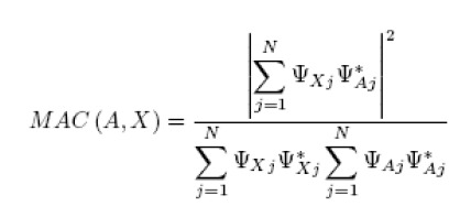
Where:
N is the number of common simulation and test mode shape components
The superscript * indicates the complex conjugate value.
There are LA x LX MAC numbers for given mode shape matrices [ΨA] and [ΨX], where LA is the number of mode shapes in [ΨA] and LX is the number of mode shapes in [ΨX]. These are presented in matrix format:
Problem Definition
We wish to compare the natural frequencies and mode shapes of an aircraft engine nacelle finite element model with the equivalent data acquired during a modal test of the actual structure:
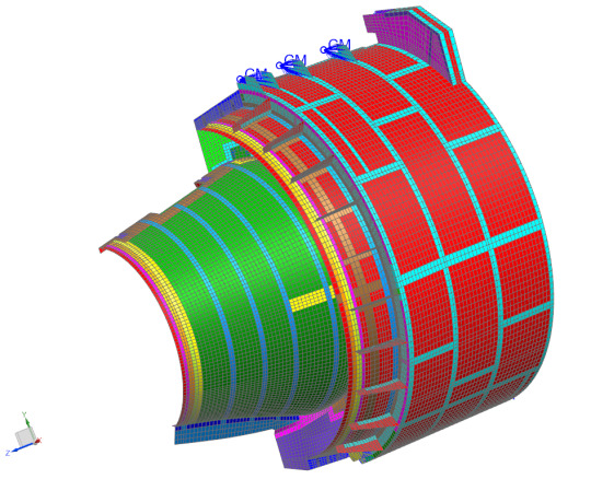
The model and test article both represent half the nacelle.
1. Normal Modes Solution
First we create an NX Nastran normal modes solution, requesting the first 20 free-free (unconstrained) modes of the FEM. The first 6 modes describe rigid body motion, in which the structure moves without any internal strain. The next 14 modes are elastic modes, which are the ones we are interested in correlating.
In the simulation navigator, select the top-most sim node and right-click New Solution
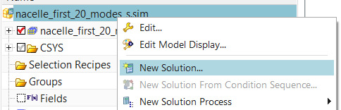
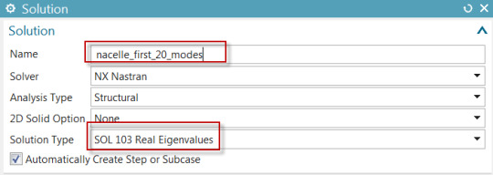
The Solution dialog pops up. Enter a Name and as Solution Type, select Sol 103 Real Eigenvalues from the list
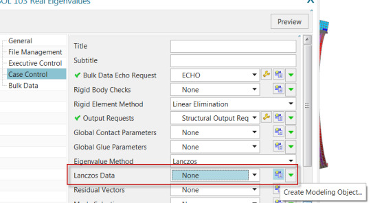
In the Case Control tab of the Solution dialog, next to Lanczos data click Create Modeling Object
In the Real Eigenvalues Lanczos dialog, enter 20 as the Number of Desired Modes. Click OK twice.
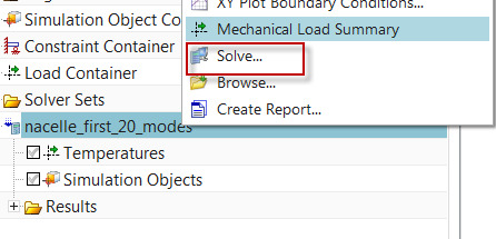
In the sim navigator, select the solution, right-click, Solve
After the solution is complete, the mode shapes can be displayed from the post navigator.
2. Import Test Geometry and Results
In the Correlation tab of the Simcenter 3D ribbon, click New Test Reference Solution
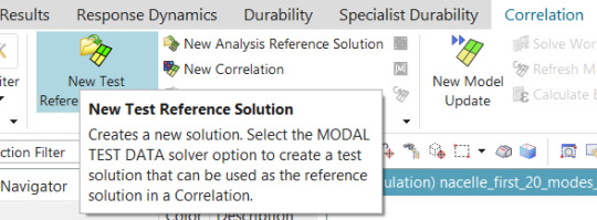
Set the Solution Type to Modal Test Data, and then select a Geometry File which contains the test geometry (test sensors, coordinate systems and traces) as well as a Modes File containing the test mode shapes and natural frequencies. In this case, the same file contains both the geometry and the mode shapes.
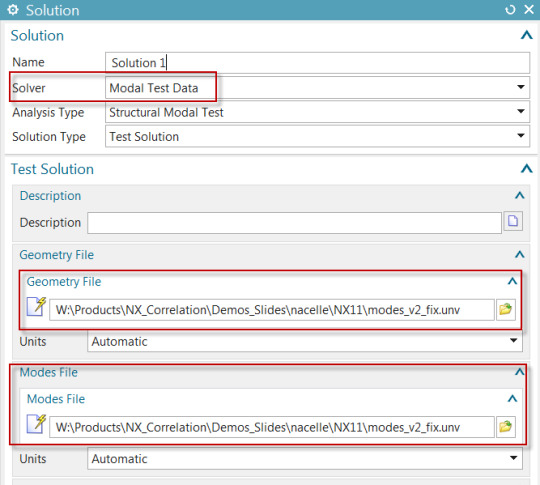
Click OK. There are now 2 solutions in the sim file.
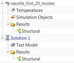
Since Solution 1 is active and points to imported geometry, the fem is now displayed as monotonic grey.
3. Align the Test Model
In the sim navigator, under Solution 1, select the Test Model node, and right-click Show Model.
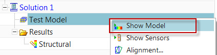
You can also click Show Sensors, to see the individual sensors as triads.
It is clear that the test model and the FEM do not share the same global coordinate system. The test model will have to be aligned with the FEM in order for correlation to be possible.
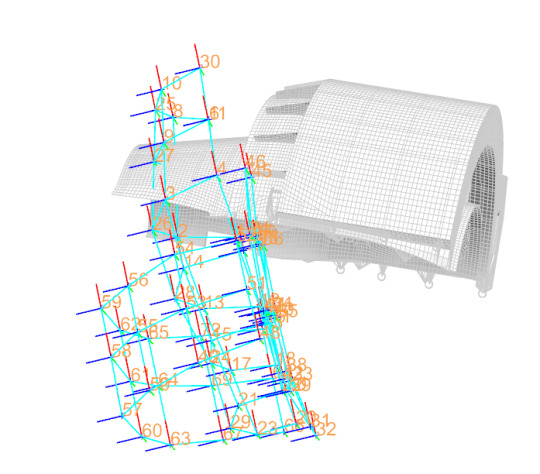
In the sim navigator, under Solution 1, select the Test Model node, and right-click Alignment. The Alignment Control dialog will appear, allowing you to choose 3 test nodes and the equivalent 3 nodes in the FEM. Checking on Preview allows you to see the cumulative effect of the pairs you have selected.
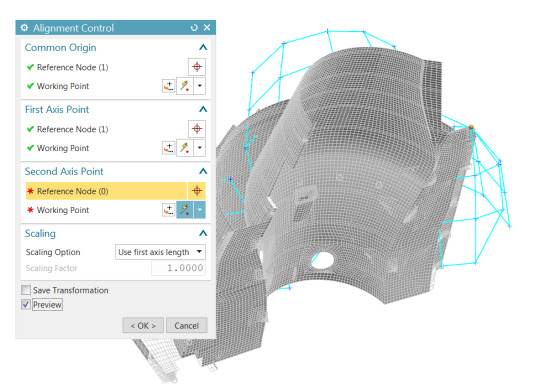
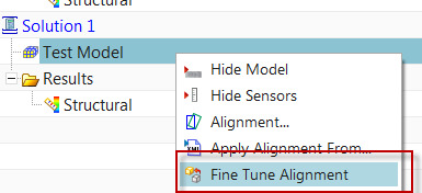
You may need to repeat this step if it is not clear which test sensors correspond to which nodes. After you have successfully performed the alignment, you may select Fine Tune Alignment to further nudge the test model by specifying discrete translations and rotations.
4. Create a Correlation
In the Correlation tab of the Simcenter 3D ribbon, click New Correlation
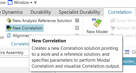
The Correlation dialog appears. Select test Solution 1 as the Reference Solution, and your normal modes solution as the Work Solution
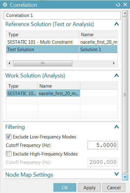
By default, low-frequency (rigid-body) modes are filtered out. In the Node Map Settings group, enter 75 mm as the matching tolerance between the test sensors and the FEM nodes. Click OK.
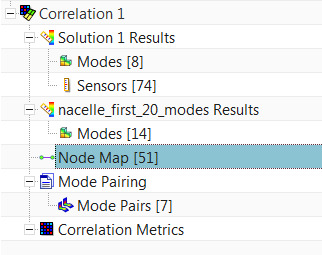
Based on the alignment that was performed, and the tolerance entered in the last step, Simcenter FE Model Correlation was able to map 51 sensors to the FE model nodes, based on proximity. If you repeat the alignment and choose different alignment node pairs, you will see a different number of paired nodes in brackets. The test and analysis mode shapes will be interrogated at these 51 locations to determine the MAC.
Next, select the Mode Pairing node under Correlation 1, right-click Edit. The default mode pairing criterion is MAC with a minimum value of 0.7: This means that test and analysis modes having the greatest MAC value above 0.7 will be paired, others will not be paired. For example, work (analysis) mode 12 is not paired to any test mode.
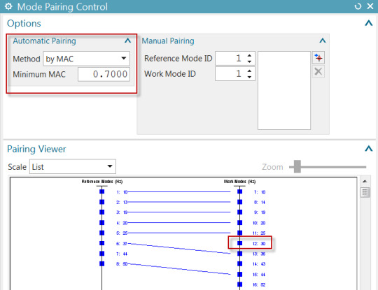
Other pairing methods can be selected.
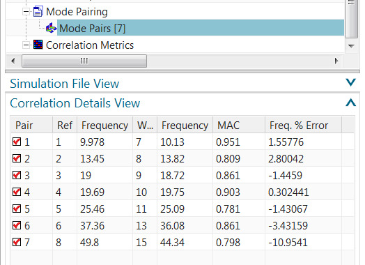
Next, select the Mode Pairs (n) node under the Mode Pairing node and click the Correlation Details View bar
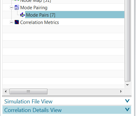
This pops up the Correlation Details View, which shows the test (reference) and analysis (work) frequencies, percent frequency error and MAC, for each mode pair.
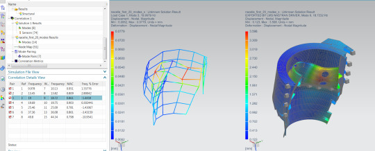
Select any mode pair row in the table, right-click Side-by-Side Animation:
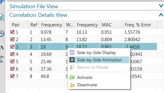
This will bring up a synchronized 2-view layout, showing the test and analysis mode shape animation
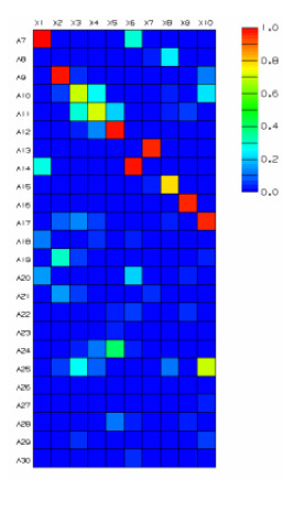
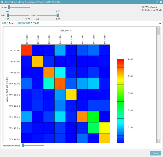
Select the Correlation Metrics node under Correlation 1, right-click Correlate. In the Correlate dialog, click Show Results Heat Map
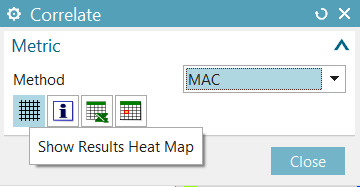
The heat map display shows the MAC matrix
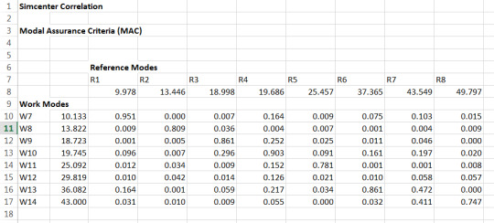
In the Correlate dialog, click Show Results Spreadsheet
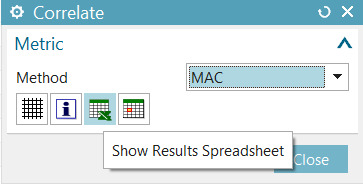
SC FE Model Correlation will send the MAC matrix to an Excel spreadsheet.
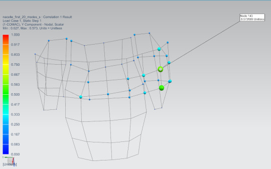
Select the Correlation Metrics node under Correlation 1, right-click Generate 1-COMAC Results.
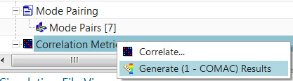
This will show sensors at which the individual MAC components are poorest.
5 notes
·
View notes
Text
Unlock Innovation and Efficiency: How Simcenter Transforms Your Business with NX CAE
How Simcenter Simulation and Test Solutions Can Transform Your Business
In today’s competitive market, predicting the performance of your designs is crucial. Simcenter simulation and test solutions enable you to do just that. By combining 1D simulation, 3D CAE, and testing, Simcenter allows you to predict performance across critical attributes throughout the product lifecycle. This powerful combination of physics-based simulations and data analytics helps you optimize your designs, deliver innovations faster, and with greater confidence.
Key Features:
Combines 1D simulation, 3D CAE, and testing.
Predicts performance across critical attributes.
Optimizes design.
Delivers innovations faster.
Increases confidence in design performance.
Benefits:
Improved product performance
Reduced development time
Lower development costs
Increased innovation
Enhanced product quality
Greater confidence in product design
Why DDSPLM?
DDSPLM Private Limited is a leading engineering solution vendor with over 25 years of experience. As a Siemens Expert Partner, they are a trusted advisor to over 700 customers, ranging from small businesses to large enterprises, across various industry verticals. Their expertise and experience make them an ideal partner for implementing and leveraging Simcenter solutions.
Conclusion
Simcenter simulation and test solutions, combined with the expertise of DDSPLM, offer a powerful way to transform your business. By accurately predicting product performance, optimizing designs, and accelerating innovation, you can gain a significant competitive advantage.

0 notes
Text
NX CAD Solutions for Manufacturing Industries
Introduction
NX CAD is a cutting-edge, integrated design and engineering software solution tailored for the manufacturing industry. Developed by Siemens, NX CAD enhances the capabilities of designers and engineers by offering advanced tools for product design, simulation, and manufacturing processes. This comprehensive solution streamlines workflows, improves collaboration, and accelerates innovation, making it a vital tool for manufacturers looking to stay competitive in today’s dynamic market.
Key Benefits
Increased Productivity: NX CAD’s intuitive interface and powerful automation tools help engineers design, model, and optimize products faster, reducing time-to-market.
Collaboration: Real-time collaboration features enable teams to work seamlessly across geographies, sharing designs and updates instantly.
Integration: Seamlessly integrates with other Siemens products like Teamcenter and Simcenter, offering a unified product lifecycle management (PLM) approach.
Innovation: The advanced simulation and visualization capabilities allow manufacturers to test and optimize designs virtually, leading to innovative, high-quality products.
Key Features
Advanced Modeling Tools: Offering parametric, direct, and freeform modeling capabilities for intricate designs.
Simulation: Built-in simulation tools to perform structural, thermal, and motion analyses.
Manufacturing Integration: Direct integration with CNC machines for manufacturing process optimization.
Design for Additive Manufacturing: Supports the creation of 3D printable models, enabling manufacturers to explore new production methods.
Applications in the Automotive Industry
NX CAD is widely used in the automotive sector for designing complex vehicle components, assemblies, and systems. It helps automotive manufacturers create innovative parts with higher precision, while also enhancing collaboration across engineering teams to ensure efficient production and quality control.
Conclusion
NX CAD provides manufacturers with a robust platform for design, simulation, and manufacturing processes. Its powerful tools and seamless integration empower industries like automotive to develop high-performance products with reduced costs and enhanced efficiency.

0 notes
Text
Siemens Simcenter 3D: Empowering Simulation Teams with Flexible CAE Licensing
Simcenter 3d: Enjoy Flexible CAE Licensing
Siemens' Simcenter 3D stands out for its commitment to providing flexibility and efficiency to simulation teams. One key aspect contributing to this adaptability is Simcenter 3D's innovative approach to licensing, introducing a value-based token licensing system.
Unlike the traditional model of purchasing individual licenses for each add-on module, Simcenter 3D's token licensing offers a more versatile and cost-effective solution. With this approach, users have the option to acquire packs of tokens, providing instant access to a wide range of Simcenter 3D modules.
The shift to a token-based licensing system brings several advantages to simulation teams:
Cost Efficiency: Token licensing eliminates the need for individual module licenses, allowing teams to optimize costs by acquiring token packs based on their specific needs. This approach provides a cost-effective solution, particularly for teams requiring access to multiple Simcenter 3D modules.
Flexibility and Instant Access: The token system enhances flexibility, enabling teams to allocate resources based on project requirements. This approach is particularly advantageous for dynamic project environments where the demand for specific modules may vary. With token packs, teams can instantly access the required modules without the constraints of traditional licensing models.
Streamlined Collaboration: Simcenter 3D's token licensing promotes collaboration by offering a shared pool of tokens that team members can draw from. This ensures that resources are utilized efficiently across the team, facilitating seamless collaboration on diverse simulation projects.
Scalability: As simulation needs evolve and projects expand, Simcenter 3D's token licensing system provides scalability. Teams can easily scale their simulation capabilities by acquiring additional token packs, aligning with the growth and changing demands of their projects.
Simplified Management: Managing Simcenter 3D licenses becomes more straightforward with token-based licensing. Teams can streamline the allocation and usage of tokens, making it easier to track and manage resources effectively.
To sum up, Simcenter 3D licensing introduces a new level of adaptability and cost efficiency for simulation teams. By moving away from traditional licensing models, Simcenter 3D empowers teams to optimize resources, enhance collaboration, and scale their simulation capabilities seamlessly. In a field where flexibility and efficiency are paramount, Simcenter 3D's approach to licensing reaffirms its commitment to meeting the evolving needs of simulation engineers.
To get a free Siemens Simcenter 3d License trial, reach out to Simulation Experts!
#siemens cae#caesoftware#cae#siemens cae software#simcenter 3d#simulation software#free cae software#siemens simulation software#siemens simcenter 3d software
0 notes
Text
Computer Aided Engineering (CAE): Siemens Simcenter 3D
In the landscape of Computer-Aided Engineering software solutions in Canada, Siemens stands out as a trailblazer with its Simcenter 3D—a robust and comprehensive suite catering to the diverse needs of CAE experts across the nation.
Canadian CAE experts seek cutting-edge solutions to tackle complex engineering challenges, and Siemens' CAE software portfolio, particularly Simcenter 3D, emerges as a powerful toolset designed to address these demands. Simcenter 3D integrates simulation, testing, and analysis capabilities into a unified platform, offering a holistic approach to engineering simulation.
Siemens' dedication to advancing CAE software in Canada is evident through Simcenter 3D's versatile functionalities. It enables engineers and analysts to simulate various scenarios across multiple disciplines such as structural, thermal, fluid dynamics, and electromagnetics. This breadth of simulation capabilities empowers users to optimize designs, predict performance, and validate product behavior with unparalleled accuracy.
The expertise of Canadian CAE professionals finds a natural fit with Siemens' CAE software, leveraging Simcenter 3D's intuitive interface and powerful simulation tools. From automotive to aerospace, manufacturing to energy sectors, Simcenter 3D's adaptability addresses industry-specific challenges, allowing CAE experts to streamline workflows and drive innovation.
Siemens' commitment to fostering a collaborative ecosystem further enhances the appeal of Simcenter 3D among CAE experts in Canada. The software's seamless integration with other Siemens solutions and third-party applications facilitates data exchange, enabling a unified engineering environment for improved efficiency and informed decision-making.
Moreover, Siemens' CAE software offerings extend beyond mere simulation tools; they embody a vision for the future of engineering. The incorporation of cutting-edge technologies such as artificial intelligence and machine learning into Simcenter 3D showcases Siemens' commitment to staying at the forefront of technological innovation, empowering Canadian CAE experts to explore new frontiers in engineering simulation.
As CAE experts in Canada navigate the complexities of engineering challenges, Siemens' Simcenter 3D remains a beacon of excellence, offering not just a suite of powerful CAE tools but a strategic partnership aimed at driving innovation, optimizing designs, and propelling businesses towards success in the dynamic landscape of engineering simulation. With Siemens CAE software, including Simcenter 3D, Canadian CAE experts find themselves equipped with the tools and support necessary to tackle the most intricate engineering puzzles and transform concepts into reality.
#caesoftware#cae#siemens cae software#CAE Experts in Canada#CAE Experts#Siemens CAE#Simcenter 3d#SImcenter 3d price
0 notes
Text
Exploring the Power and Capabilities of Simcenter 3D in Engineering Simulation
In the dynamic realm of engineering and product design, simulation plays a pivotal role in driving innovation, ensuring product efficiency, and reducing development costs. Siemens Digital Industries Software offers a robust solution in the form of Simcenter 3D, a comprehensive CAE simulation platform that empowers engineers and designers to analyze, simulate, and optimize their designs across various industries. From automotive to aerospace, from electronics to heavy machinery, Simcenter 3D stands as a versatile and powerful tool.
Simcenter 3D: A Comprehensive Simulation Platform
Simcenter 3D is more than just a simulation software; it's a complete ecosystem that integrates multiple simulation disciplines into a unified environment. It allows engineers to perform various analyses, such as structural, thermal, vibration, motion, and computational fluid dynamics (CFD), among others. This comprehensive suite covers the entire simulation process from geometry preparation to result visualization.
Key Features and Capabilities:
Multi-physics Simulations: Simcenter 3D excels in providing a platform for multi-physics simulations, enabling engineers to analyze complex interactions between different physical phenomena. It integrates structural, thermal, and fluid dynamics simulations to provide a holistic understanding of product behavior.
Integrated Workflow: Its unified environment allows for a seamless transition between different analyses. Engineers can effortlessly move from CAD geometry to meshing, apply various boundary conditions, and conduct simulations, all within a single interface.
Optimization and Design Exploration: The software facilitates design exploration and optimization studies. Engineers can use optimization algorithms to refine and enhance designs by automatically iterating through various design configurations, leading to improved performance and cost-efficiency.
High-Fidelity Results: Simcenter 3D is recognized for its ability to deliver high-fidelity results. It accounts for material properties, manufacturing processes, and complex behaviors, providing accurate simulations for real-world scenarios.
Adaptive Meshing: Its adaptive meshing technology allows for efficient mesh generation, ensuring accurate results while reducing computational overhead.
Extensive Material Libraries: The software incorporates a vast material library, enabling users to select from a wide range of materials for their simulations, ensuring accuracy and reliability.
Applications across Industries:
Simcenter 3D finds applications across diverse industries, such as automotive, aerospace, industrial machinery, electronics, and more. In automotive design, engineers use Simcenter 3D for crash analysis, durability simulations, and noise, vibration, and harshness (NVH) studies. Aerospace engineers utilize the software for aerodynamic analysis, structural integrity, and thermal management in aircraft and space systems.
Future Innovations and Trends:
Looking ahead, the future of Simcenter 3D involves further advancements in predictive engineering. The software is expected to leverage artificial intelligence and machine learning for predictive simulations, reducing the reliance on physical testing and accelerating the design process.
Simcenter 3D stands as a cornerstone in the field of engineering simulation, offering a powerful and comprehensive solution for design and analysis. Its ability to unify various simulation disciplines, its extensive capabilities, and its application across diverse industries make it an invaluable asset for engineers and designers aiming to develop efficient, reliable, and innovative products. As technology continues to evolve, Simcenter 3D is poised to play a pivotal role in shaping the future of engineering design and simulation.
0 notes
Text
Pioneering the Future: Siemens Simcenter CAE Leads the Way in Emerging CAE Trends
In the ever-evolving world of engineering and product design, the role of Computer-Aided Engineering (CAE) software has never been more crucial. CAE tools, like Siemens Simcenter 3D Software, are not just keeping up with the times; they are blazing a trail into the future. In this article, we'll dive into the exciting emerging trends in CAE, with Siemens Simcenter CAE as our hero, leading the charge.
The CAE Revolution Continues
CAE has come a long way from its early days, where it was primarily used for structural analysis and simulation. Today, CAE is at the forefront of innovation, shaping the future of product development and engineering. Let's explore some key trends that are reshaping the CAE landscape:
1. AI and Machine Learning Integration:
Imagine having a virtual assistant that can analyze vast amounts of simulation data, predict potential issues, and optimize designs in real-time. That's the power of AI and machine learning in CAE. Siemens Simcenter CAE has been at the forefront of this trend, integrating AI and machine learning to enhance simulations.
Example: Siemens Simcenter offers AI-driven design exploration tools that can quickly evaluate thousands of design variations, helping engineers find the best solutions faster than ever before.
2. Digital Twins:
Digital twins are like having a virtual clone of a physical product. They allow engineers to monitor, simulate, and optimize a product's performance throughout its lifecycle. Siemens Simcenter CAE Software has embraced the digital twin concept, making it an integral part of the product development process.
Example: With Siemens Simcenter CAE, engineers can create a digital twin of a car engine. They can simulate its performance under various conditions, ensuring it runs smoothly and efficiently in the real world.
3. Cloud-Based CAE:
The cloud has revolutionized how we access and process data, and CAE is no exception. Cloud-based CAE solutions, like those offered by Siemens Simcenter, enable engineers to access powerful simulation capabilities from anywhere, collaborate seamlessly, and scale resources as needed.
Example: Siemens Simcenter 3D offers cloud-based simulation solutions that allow engineers to perform complex simulations without the need for expensive hardware or software installations.
4. Multidisciplinary Optimization (MDO):
Optimizing a product for multiple objectives and constraints can be a daunting task. MDO, supported by Siemens Simcenter CAE, helps engineers find the best compromise between conflicting design goals, resulting in more innovative and efficient products.
Example: Siemens Simcenter offers MDO tools that enable engineers to explore design trade-offs, such as weight versus performance, and automatically generate optimized designs.
5. High-Performance Computing (HPC):
Complex simulations demand immense computing power. Siemens Simcenter CAE leverages high-performance computing to tackle large-scale simulations efficiently, reducing analysis time and accelerating innovation.
Example: Siemens Simcenter offers HPC solutions that enable engineers to perform simulations with millions of elements, such as crash tests or fluid dynamics, in a fraction of the time.
Conclusion: Siemens Simcenter CAE – Leading the CAE Revolution
As we journey into the future of CAE, Siemens Simcenter stands as a beacon of innovation and progress. With AI and machine learning integration, digital twins, cloud-based solutions, MDO capabilities, and high-performance computing, Siemens Simcenter CAE is driving the industry forward. It empowers engineers and designers to create better, more efficient products while reducing development time and costs. As emerging technologies continue to shape the CAE landscape, Siemens Simcenter CAE remains the hero at the forefront, pioneering the way to a smarter, more efficient future in product development and engineering.
1 note
·
View note
Text
How to map flow forces to a structural analysis in Simcenter
Quick Overview
Simcenter offers a dedicated application to map steady state or transient flow results onto a target model, typically an independent structural model from the same geometry but with a different mesh. For example, one could be interested in the stress and distortion analysis of a canopy due to wind forces.
The target FEM must use the same global coordinate system as the source FEM, and both models should be geometrically congruent. However, they need not share the same mesh. Results are mapped from the selected solution on the source model, to a solution on the target model, based on proximity and with optional zone associations. The output of the mapping solution can then be used by the target solution.
In what follows, we describe how to create an NX Nastran structural analysis using forces that are mapped from a Simcenter Thermal/Flow analysis.
Workflow overview
The main steps are:
Create a part file containing the structure and air volume.
Create a Simcenter Thermal/Flow fem file with only the air volume meshed.
Create a new Simulation containing a Thermal/Flow Solution with Flow Analysis.
Run the Thermal/Flow Solution.
Back to the part file; create a NX Nastran fem file of the structure.
Create a new Simulation containing a Thermal/Flow Solution with Mapping Analysis.
Specify the mapping target area then Solve.
Assign the structural boundary conditions and solve the structural analysis.
For more information, see Simcenter Thermal/Flow, Electronic Systems Cooling, and Space Systems Thermal documentation.
Create the Thermal/Flow Simulation
1. Create the part
We begin by creating the part file, as shown in Figure 1. This represents a simple tubular structure submitted to lateral winds.

Figure 1: Part file containing both structure and fluid volume
2. Create the Thermal/Flow FEM
Next, create the fem file. In the “Edit FEM” window, make sure to choose Simcenter Thermal/Flow (Flow) as the “Solver Environment”, as shown in Figure 2.
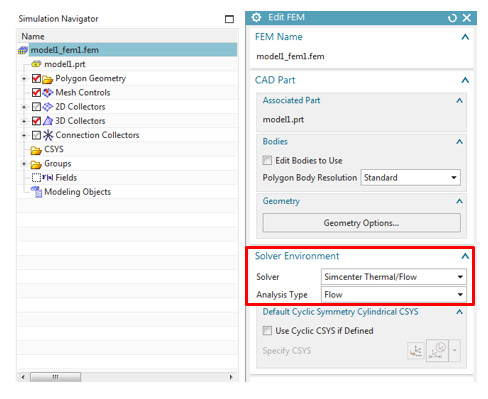
Figure 2: Creating the Thermal/Flow fem
Then create a 3D mesh for the air volume, as shown in Figure 3.

Figure 3: Mesh the air volume only. The structure is not meshed.
3. Create the Flow Solution
We now create the “Simulation” file, and define a “Flow” analysis. As shown in Figure 4, define a non-turbulent transient analysis. Furthermore, in the “Result Options”, see Figure 5, check the “Pressure and Shear Resultants” box – these will be used for the mapping step.

Figure 4: Flow Solution setup
Then, edit the “Transient Setup” tab as illustrated in Figure 5.

Figure 5: Results Options for flow forces

Figure 6: Transient setup options
4. Apply the boundary conditions.
Three boundary conditions are applied:
An inlet of 30 mm/sec at ambient conditions on the –Y faces.
An opening at ambient conditions on the +Y faces.
Slip walls to represent an extended fluid domain on the +X, -X and +Z faces.
As nothing is prescribed on the bottom surface, the solver automatically assumes no-slip, which represents a solid surface. Boundary conditions are shown in Figure 7.

Figure 7: Boundary conditions
We now solve this Flow solution. An example of the flow velocity profiles is shown in Figure 8.
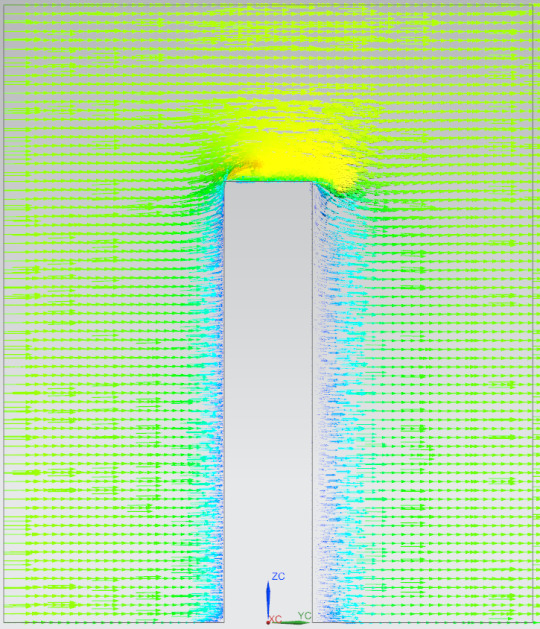
Figure 8: Flow velocity profile.
Mapping the flow forces
1. Create the structural mesh
Starting with the same part created in step 1, create a new fem file. In the “Edit FEM” window, make sure to choose the NX Nastran (Structural) “Solver Environment”, as shown in Figure 9.

Figure 9: Creating the Structure fem
This time, we will only mesh the structure component and ignore the air volume. See Figure 10. An aluminum material is assigned to the tube.

Figure 10: Structure mesh only. The air volume is not meshed.
2. Create the Mapping Solution
To map the flow forces to the structural analysis, create a new “Simulation” file and choose a “Thermal-Flow” Solution with a “Mapping” type, as shown in Figure 11. If you leave the “Transient Times” table empty, the solver automatically selects all transient time steps from the flow solution.
Figure 11: Create a Mapping Solution
Next, in the “Optional Output” tab, check the boxes shown in Figure 12 to create the mapping and target Nastran structural solution. A static solution is created. This type of analysis is valid when inertial effects are negligible and where the dynamic content of the flow pressures is well separated from the structures principal modes.
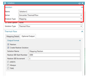
Figure 12: Creating the Mapping and Nastran Solution
3. Solve the Mapping Solution
Before solving the Mapping Solution, we define a “Mapping Target Set”. This defines the surfaces on which the flow forces will be mapped. Select the cylindrical face of the tube and its free face, as shown in Figure 13 and Figure 14. We can now solve the Mapping Solution. An example of the mapped forces at a given time step is shown in Figure 15.

Figure 13: Mapping Target Set

Figure 14: Select the mapped surfaces

Figure 15: Example of mapped forces
4. Solve the structural solution
The “Simulation Navigator” now shows one subcase corresponding to each transient time step of the flow solution. See Figure 16.

Figure 16: Subcase created for each transient time step of the flow solution
Before solving, we fix the translational degrees of freedom on the –X face of the tube. Solve the solution.
5. View displacement results
Next, select a subcase and display the displacement results, as shown in Figure 17. The deformed structure is shown together with the undeformed mesh in Figure 18.
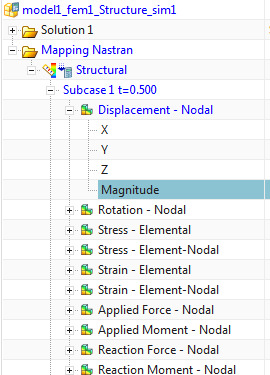
Figure 17: Nodal displacement results

Figure 18: Deformed and undeformed structure
3 notes
·
View notes
Text
How to simulate delamination using cohesive elements in Simcenter Multiphysics
Quick Overview
Cohesive elements are special-purpose 3D elements used to model adhesive joint failure as well as delamination of composite plies. You can create cohesive elements between pairs of geometric surfaces and between specific plies, in both the Simcenter Multiphysics and Samcef environments of Simcenter 11 Pre/Post.
In what follows, we focus on the Simcenter Multiphysics environment and describe how to create cohesive elements between plies in a global layup, in order to simulate delamination using a 3D laminate composite model.
Introduction to cohesive elements in Simcenter Multiphysics
In this environment, cohesive elements can be used to:
Model delamination between plies in a laminate composite.
Simulate the presence of an adhesive between bonded surfaces. Cohesive elements offer several advantages over traditional glue-type connections, especially in situations where the integrity and strength of the connection are of interest.
Several options exist to include cohesive elements in an analysis:
You can use the “3D Swept Mesh” command with type set to “Manual Between”, in order to create a layer of cohesive elements between specified source and target faces. If the source and target faces are coincident, the software generates zero thickness cohesive elements.
You can use the “Element Extrude” command with the type set to “Element Faces”, in order to manually generate cohesive elements.
You can use the Simcenter Laminate Composites’ “Layup Modeler” dialog to create cohesive layers between specific plies.
The cohesive element’s material type can be “Isotropic”, “Orthotropic” or ”Damage Interface”. The “Damage Interface” material type evaluates the cohesive layer integrity during the nonlinear solution. You can use options in the “Damage Interface” material dialog box to specify, amongst others, the damage estimation model.
For more information, see Simcenter Multiphysics “Damage Interface” material and Samcef “Damage Interface” material.
Create a cohesive element layer
We begin with an inflated 3D laminate, as shown in Figure 1.

Figure 1: Example of an inflated 3D laminate
1. Create a “Damage Interface” material
Using “Manage Material”, create a “Damage Interface”-type material, as shown in Figure 2.

Figure 2: Defining a "Damage Interface"-type material
Enter the fracture toughness and stiffness for each of the 3 failure modes: these properties are derived from tests. In this case, we use an exponential-type damage law. See Figure 3:

Figure 3: Interface constitutive behavior and properties
2. Create cohesive elements between plies
In the “Layup Modeler”, shift-select two ply groups and click the “Create New Cohesive Layer” button.

Figure 4: Create a cohesive layer
Then, assign the previously created “Damage Interface”-type material to the cohesive layer. This is illustrated in Figure 5.
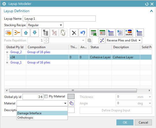
Figure 5: Assign the created material to the cohesive layer
Setting up the simulation
1. Create the simulation and solution
Create a new Simcenter Multiphysics simulation and solution, keeping “Automatically Create Step or Subcase” checked:

Figure 6: Create a Simcenter Multiphysics solution
In the “Solution Control” tab, check the “Material Nonlinearity” box (See Figure 7).

Figure 7: "Solution Control" tab
From the “Result Options” tab, edit the “Structural Output Request” (see Figure 8):
Set the “Damage” of the Cohesive Element Results to “DAMAGE”.
Set the “Output Medium” of the Cohesive Element Results to “PLOT”.

Figure 8: "Output Request" menu
2. Define the boundary conditions
The -X face of the coupon is completely fixed, while Mode 1 delamination is solicited by defining equal and opposite 1 mm displacements to the top and bottom nodes of the +X face. This is shown in Figure 9 and Figure 10.

Figure 9: Fixed Constraints and Enforced displacements

Figure 10: Constraints in Sim Navigator
3. Define the time step
To define the time integration parameters, select the “Step – Nonlinear Static” node in the sim navigator, then right-click “Edit”, and in the “Time Step Definition” tab, set the “End Time” to 1 sec and the “Number of Increments” to 20. See Figure 11 and Figure 12.

Figure 11: Edit the time integration controls

Figure 12: Specify solution time and time step
4. Run the simulation and animate the damage results
Next, launch the solution and subsequently load the “Cohesive Damage [EXPO] – Element Nodal V1” results. In the “Post Processing Navigator – Fringe Plot”, display only the cohesive elements, as shown in Figure 13:

Figure 13: Display the cohesive elements
To animate the results across all the iterations of the nonlinear solution, use the “Animate” button in the ribbon bar. A damage value of 1 indicates a complete delamination of the plies. Use the animation options shown in Figure 14:

Figure 14: Animate the results

Figure 15: Animation of the delamination results.
1 note
·
View note