#Stm32f103c8t6
Explore tagged Tumblr posts
Visit Tumblr Blog
Explore Tumblr blogs with no restrictions, modern design and the best experience.
Last Seen Tumblr Blogs


Fun Fact
In 2020, 27% of US Tumblr users had an annual household income of over $100,000.
Video
youtube
china electronic components #TM1620 #DSP56311VL150 #FREESCALE DSP #STM32F103C8T6 #ST #STMicroelectronics #MCU #chip #INDUSTRIALCONTROLCHIP #icgoodfind #IC #Electronics Skype:[email protected] www.icgoodfind.com
2 notes
·
View notes
Link
Si4732 + Si5351 + STM32F103C8T6 Receptor multimodo https://www.te1.com.br/?p=44922 Por Toni Rodrigues Toni Eletrônica Circuitos...
0 notes
Link
0 notes
Photo

STM32F103C8T6 Development Board STM32 ARM Core Module The STM32 Development is based on the ARM Cortex M3 STM32F103C8T6 Microcontroller from STMicroelectronics. The controller works on 3.3V and can be powered by 5V since it has an internal 3.3V regulator. It has dual crystal oscillators (8MHz and 32KHz) which runs the internal RTC and supports Deep sleep modes for energy constraint battery operated applications.The Board also has two on-board LEDs, one red color LED for power indication and a Green color programmable LED connected to GPIO pin 13. The Board should be toggled between MCU boot mode and Programming board using the two header pins.
Know more about STM32F103C8T6 Development board
4 notes
·
View notes
Text
Virtual electronic finderscope for the Stellarium
StarPointer is a virtual electronic finderscope for astronomical telescopes. This device works with Stellarium and helps the observer identify objects in the sky.
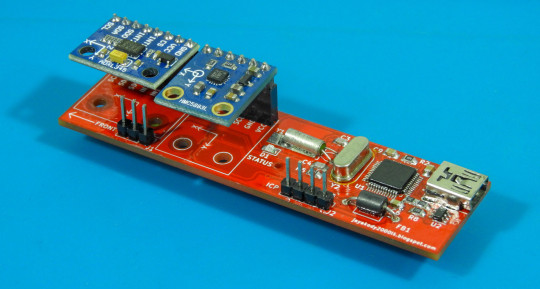
This unit can be attached to the telescope without modifications and connects with the computer through the USB port. The StarPointer uses a few onboard sensors to determine its angle and position. After obtaining that information, the unit calculates the RA (right ascension ) and DEC (declination) coordinates of the telescope and transfers those details to the Stellarium.
The StarPointer builds around the STM32F103C8 microcontroller, ADXL345 3-axis accelerometer, and HMC5883L 3-axis magnetometer. This unit communicates with the PC using the inbuilt USB peripheral of the STM32F103C8 microcontroller. The firmware of the StarPointer is developed using the LibOpenCM3 library and built using GNU ARM Embedded Toolchain.
youtube
This unit can attach to any astronomical telescope or binocular regardless of its type or mount. After attaching the unit, the user needs to calibrate the StarPointer using the configuration software. This configuration software allows StarPointer to set the latitude and longitude of the observation location, RTC date/time, and RA and DEC offsets. After performing the above steps, the unit is ready to use with the Stellarium.
The StarPointer is designed to work with Stellarium's telescope control plugin. Its firmware has been developed to work with the Meade LX200 communication protocol, and no additional modifications are needed for Stellarium to work with this sensor kit.
When assembling the sensor module, we strongly recommended using the genuine STM32F103C8T6 MCU for this project. During the prototyping stages, we found a few counterfeit STM32F103C8T6 MCUs which are not working properly with this firmware. According to our observations, most of the counterfeit STM32F103C8T6 MCUs failed to initialize the RTC and USB peripherals at the startup.
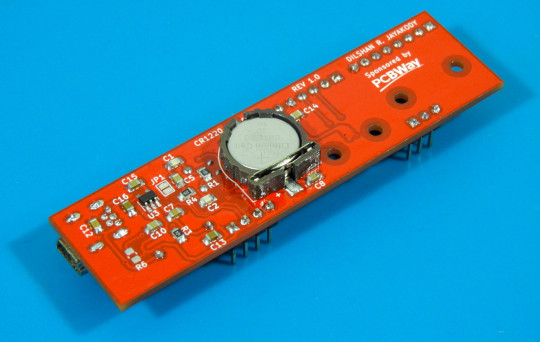
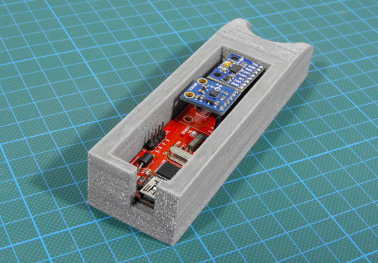
We also design a suitable enclosure for this project, and its design files are available to download at tinkercad.com. This design can be 3D printed using either ABS or PLA. To get the optimal results, we recommended attaching this enclosure to the piggyback bracket of the telescope.
The PCBWay sponsored this project. PCBWay offers high-quality PCB manufacturing and assembling services. Also, they offer CNC and 3D printing services. The StarPointer PCB is available to order from PCBWay. The StarPointer enclosure can also order from the PCBWay 3D printing service. Check out the PCBWay website for their manufacturing capabilities and pricing.

StarPointer is an open hardware project. All design files, firmware/application source codes, and schematic files are available to download at the project GitHub repository. The complete documentation is also available in the Wiki section of the GitHub repository.
#accelerometer#ADXL345#ARM#CDC#celestron#finderscope#gcc#HMC5883L#lazarus#LibOpenCM3#LX200#magnetometer#Meade#PCBWay#RT9193-33#Stellarium#STM32F103C8T6#telescope#USBLC6-2SC6#USB#RTC#Youtube
0 notes
Link
Over Amaxchip's 20 years has procured a diverse range of electronic supplies from a large variety of electronic component manufacturers ranging from Texas Instruments to STMelectronics and many more. Amaxchip can aid you in all of your electronic componenet needs.
#Electrical Parts Store#Electronic Parts Supplies#Lm2596#Stm32f103c8t6#Capacitors For Sale#Mlcc Capacitor
0 notes
Photo

#STM32F103C8T6#ST(Khross electronics co.크로스전자에서) https://www.instagram.com/p/CTwXIhuhgVm/?utm_medium=tumblr
0 notes
Photo

RABPS 32bit
#Shared Projects (Reprap Arm BluePill Shield STM32F103C8T6)
made by #pcbwayer 3dmaniack from 3dtoday.ru
-
Learn more: https://bit.ly/33ZKzjE
-
#RABPS#32bit#pcb#pcba#pcbway#raspberry pi#arduino#embedded#electronics#maker#pcbwayer#shared project#open source#programming
4 notes
·
View notes
Text
STM32F103C8T6 development board, program arm stm32 arduino
Intro for STM32F103C8T6
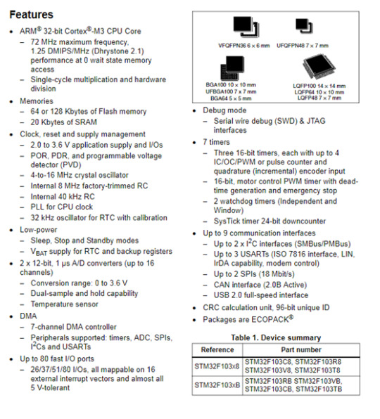
The STM32F103C8T6 is a development board for the ARM Cortex-M3 processor, designed to provide a low-cost platform that can still meet the requirements of many developers. These board's features make it ideal for a wide range of applications such as motor control, power management, medical and handheld equipment, PC and gaming peripherals, GPS platforms, industrial applications and more.
STM32F103C8T6 medium-density performance line family incorporates the high-performance ARM Cortex-M3 32-bit RISC core operating at a 72 MHz frequency, high-speed embedded memories (Flash memory up to 128 Kbytes and SRAM up to 20 Kbytes), and an extensive range of enhanced I/Os and peripherals connected to two APB buses. All devices offer two 12-bit ADCs, three general purpose 16-bit timers plus one PWM timer, as well as standard and advanced communication interfaces: up to two I2Cs and SPIs, three USARTs, an USB and a CAN. The devices operate from a 2.0 to 3.6 V power supply. They are available in both the –40 to +85 °C temperature range and the –40 to +105 °C extended temperature range. A comprehensive set of power-saving mode allows the design of low-power applications.
Tutorial to Program STM32F103C8T6 ARM STM32 arduino
STM32F103C8T6 is a very cheap but very fast ARM STM32 micro controller. You can run simple sketches very easy by following the steps below. 1. Download the latest Arduino IDE from arduino.cc and extract it. You can also download the Arduino IDE .exe file and install it to your computer. 2. After downloading the file from this link, extract it and copy the Arduino_STM32-master to your Arduino / hardware folder that you extract in the first step. If you have downloaded the .exe file then go to C:\Programs\Arduino\hardware. 3. Run the Arduino IDE, choose settings: 'Board: Generic STM32F103C series' 'Variant: STM32F103C8 (20k RAM, 64k Flash)' 'Upload method: Serial' 'Port: <the COM port of your USB-to-serial adapter>' 4. Go to File->Exampls A_STM32_Exampls->Digital->Blink and change the PB1 to PC13. 5. Put Boot1 to 1 by moving the jumper for 0 to 1, Press the Reset button and hit Upload on the Arduino IDE. After uploading if all went well the LED will blink every 100ms. Put Boot1 to 0 again so the next time you power up the micro controller the program will star automatically. You can also try to read an analog value. Go to File->Exampls A_STM32_Exampls->Analog->AnalogInSerial. Change the const int analogInputPin = 15; to const int analogInputPin = PA0; and hit upload. Open the Serial Monitor on the Arduino IDE, the value will be from 0 to 4095, it has 4 times the resolution of an arduino.
Features of STM32F103C8T6
Embedded Flash memory
- Up to 128 Kbytes of embedded Flash is available for storing programs and data.
Embedded SRAM
- Up to 20 Kbytes of embedded SRAM accessed (read/write) at CPU clock speed with 0 wait states.
Boot modes
At startup, boot pins are used to select one of three boot options:
- Boot from User Flash
- Boot from System Memory
- Boot from SRAM
The boot loader is located in System Memory. It is used to reprogram the Flash memory by using the USART.
Power supply schemes
- VDD = 2.0 to 3.6 V: external power supply for I/Os and the internal regulator. Provided externally through VDD pins.
- VSSA, VDDA = 2.0 to 3.6 V: external analog power supplies for ADC, Reset blocks, RCs and PLL. In VDD range (ADC is limited at 2.4 V).
- VBAT = 1.8 to 3.6 V: power supply for RTC, external clock 32 kHz oscillator and backup registers (through power switch) when VDD is not present.
>>Read more
0 notes
Text
STM32F103C8T6 Minimum System Board Microcomputer STM32 ARM Core Board
165.00 EGP

Microohm-eg.Com is a leading online electronics store in Egypt. You can buy all kinds of electronic products such as microcontrollers, raspberry pi 4, and Arduino sensors shield at an affordable price. For more info, visit our website.
electronics stores in egypt
0 notes
Text
Electronic components
TPS7A6650QDGNRQ1
TPS7B8250QDGNRQ1
STM32F103C8T6
STM32F407VET6
TPS53513RVER
STM8S003F3P6TR
TPS7B7702QPWPRQ1
TMS320F28335PGFA
STM32H750VBT6
DS90UB954TR
TPS65982ABZBHR
TPS65983BAZBHR
Email: [email protected]
WhatsApp: +86 18018758065
Skype:JINHEXIN-Willy,18664341585 live:.cid.2dae6a7df27be519
WeChat:+86-18664341585
Web:https://jinhexun.dzsc.com/

0 notes
Text
ARM Cortex-M3 STM32F103C8T6 Dev board Core Board
ARM Cortex-M3 STM32F103C8T6 Dev board Core Board

lastest_volume
0
Just For Today
Click Here To Visit The Shop
N€W ARM Cortex-M3 STM32F103C8T6 Dev board Core Board
0 notes
Text
New original STM32F103C8T6 STM32F103C8T6TR MCU 32BIT 64KB FLASH 48LQFP
New original STM32F103C8T6 STM32F103C8T6TR MCU 32BIT 64KB FLASH 48LQFP

New original STM32F103C8T6 STM32F103C8T6TR MCU 32BIT 64KB FLASH 48LQFP
Price
5 Catch me HERE
0 notes
Link
Product Description: This is a core chip based on the STM32F103C8T6ARM core board. Its functions are as follows: 1. The motherboard is based on the most basic MCU circuit, 8M and 32768 crystal ...
0 notes
Text
Using STONE TFT LCD Control WS2812B_RGB lamp
Using STONE TFT LCD Control WS2812B_RGB lamp
This article documented the process of controlling the WS2812B_RGB lamp using the STONE display module.
This project is to achieve RGB lamp control:
1. Change the color of the light
2. Change the brightness of the light
3. Change the four modes of the lamp

STONE TFT-LCD
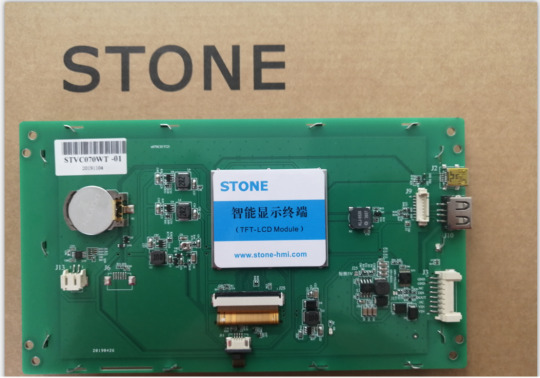
The STONE STVC070WT-01 is a 7-inch display module with a resolution of 800*480.This display module can be purchased from the official website of STONE. The communication mode is uart-rs232 and uart-ttl.The development method is very simple, MCU only needs to send instructions to STONE display module to control the display content through UART. In the same principle, when the user touches the STONE display module, the display module also sends relevant instructions to MCU through UART, and MCU then controls the device (WS2812B_RGB lamp in this project).
STONE STVC070WT-01
The following picture shows the package and accessories I received:

LIST:
1. Connection and interface
2. USB to TTL adapter plate
3. Usb flash drive (including development information)
4. Micro USB cable
5. USB transfer board
6. STONE STVC070WT-01 display module
7. 12V power adapter
The function of the STONE TFT LCD
- built-in Cortex CPU and driver
- can be controlled by any single chip microcomputer
- show pictures/text/curves
-65536 color TFT display
- can be touched
- RS232/ RS485/ TTL UART interface and USB port
- wide voltage range
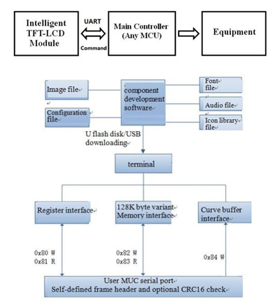
How the STONE tft-lcd display module works
The tft-lcd module communicates with the customer's MCU through commands (hexadecimal code), and the MCU then controls the connected device to work according to the commands received.
The development steps for the STONE module
Use STONE's tft-lcd module in only 3 steps:
l Design a beautiful set of graphical user interfaces.
l Connect directly to the client's MCU via RS232, RS485 or TTL.
l Write a simple program, by the MCU command control TFT-LCD module.(hex).
TFT LCD module serial command frame consists of 5 data blocks, all serial command or data are expressed in hexadecimal format.Data transfer in MSB mode.For example, for 0x1234, first send 0x12, then 0x34.
Application scenarios of STONE tft-lcd display module
The following 9 application scenarios are described on STONE's official website:

STONE display module is widely used in various industrial fields, such as:
Medical beauty equipment, construction machinery and vehicle equipment, electronic instruments, industrial control system, power industry, civil electronic equipment, automation equipment, transportation.
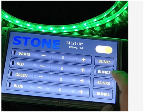
UI image design for STONE TFT-LCD
The interface designed by using Photoshop is as follows:
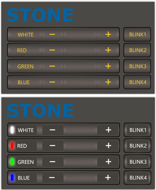
The first picture is the main screen picture, and the second picture is the effect when the button is pressed.
Use TOOL2019 software to generate LCD module configuration files
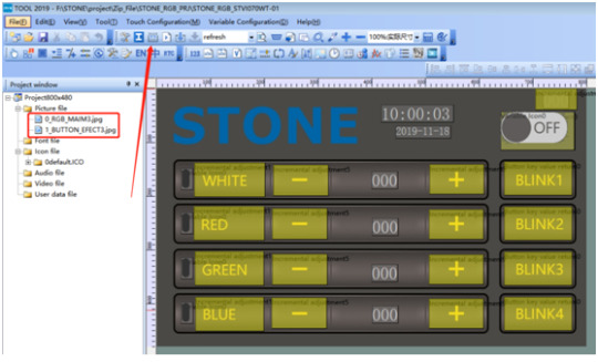
Click the button indicated by the arrow to generate the configuration file, and then download the configuration file into the display module to display the UI interface we designed.
This part of the content and tutorial I do not go into detail, you can go to STONE website to download a very detailed tutorial.
Wiring and welding
Having completed the touch display control above, we can focus on the development of MCU and WS2812B_RGB lamps.
But before that, we need to do some welding.
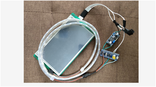
Wiring diagram
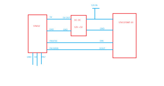
The power adapter is 12V, which needs to power the STONE STVC070WT-01 display module and to power the MCU module and WS2812B_RGB lamp by lowering the voltage to 5v through the dc-dc buck.
Accessories used in the project

Main accessories are:
1. STM32F103C8R6 module
2. Dc-dc buck module
3. UART connection
Since the communication mode of STONE STVC070WT-01 is uart-ttl by default, we do not need the RS232 interface for the connection connection. Remove the RS232 interface:

welding
Weld these parts together and the effect is as follows:
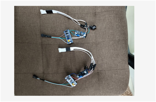
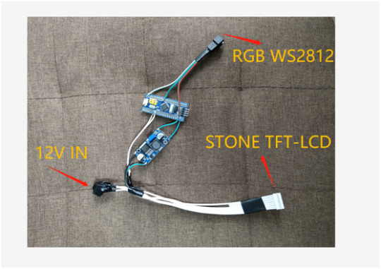
There are three interfaces, as shown above.
When this part is ready, you can program the MCU.But before we do that, we need to determine how the WS2812B_RGB lamp will be driven.
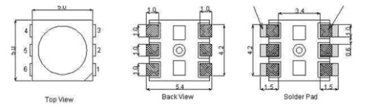
WS2812B
WS2812B is actually an RGB driver chip.
The control circuit and RGB chip are integrated in a 5050 package of components to form a complete pixel point.
Built-in signal shaping circuit, any pixel received the signal after waveform shaping output, to ensure that the waveform distortion of the circuit
Accumulation.
Built-in power on reset and power off reset circuit.
The color of each pixel can achieve 256 levels of brightness display, complete the full color display of 16777216 colors,
Serial interface, can complete data reception and decoding through a signal line.
The transmission distance between any two points is no more than 5 meters without any additional circuit.
When the refresh rate is 30 frames/SEC, the cascade number of low-speed mode should be no less than 512 points, and that of high-speed mode should be no less than 1024 points.
Data transmission speed up to 8Kbps.The color of the light is highly consistent and cost-effective.
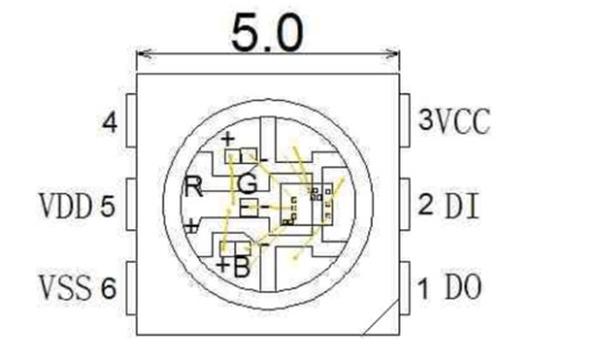
1 DOUT: Data output, control data signal output
2 DIN: Data input, control data signal input
3 VCC: Logic power supply, control circuit power supply
4 NC
5 VDD: Power supply, LED power supply
6 VSS: GND
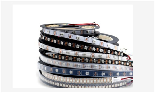
Application field
LED full-color light string, LED full-color module, LED full-color soft light bar hard light bar, LED guardrail tube, LED point light source, LED pixel screen, LED special-shaped screen, various electronic products, electrical equipment running horse light.
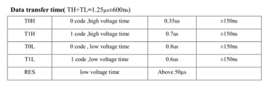
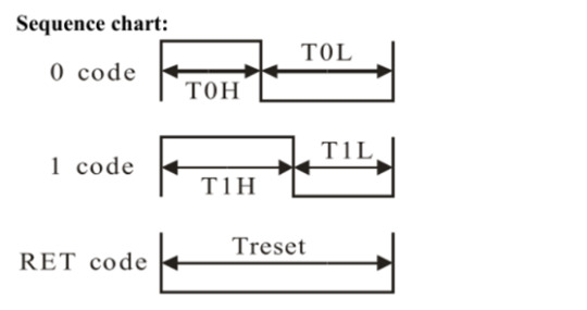
Driver for WS2812
The driving mode of WS2812 is simple. MCU only needs a signal line to complete the brightness and color control.
STM32 driver code
#include "../BOARD/ws2812/ws2812.h"
#include "usart.h"
#include "delay.h"
uint8_t PIXEL_NUM=60;
#define RGB_LED GPIO_Pin_7
#define RGB_LED_HIGH (GPIO_SetBits(GPIOA,RGB_LED))
#define RGB_LED_LOW (GPIO_ResetBits(GPIOA,RGB_LED))
void RGB_LED_Init(void)
{
GPIO_InitTypeDef GPIO_InitStructure;
RCC_APB2PeriphClockCmd(RCC_APB2Periph_GPIOA, ENABLE);
GPIO_InitStructure.GPIO_Pin = GPIO_Pin_7;
GPIO_InitStructure.GPIO_Mode = GPIO_Mode_Out_PP;
GPIO_InitStructure.GPIO_Speed = GPIO_Speed_50MHz;
GPIO_Init(GPIOA, &GPIO_InitStructure);
GPIO_SetBits(GPIOA,GPIO_Pin_7);
}
/********************************************************/
//
/********************************************************/
void RGB_LED_Write0(void)
{
RGB_LED_HIGH;
__nop();__nop();__nop();__nop();__nop();__nop();
RGB_LED_LOW;
__nop();__nop();__nop();__nop();__nop();__nop();__nop();__nop();__nop();__nop();
__nop();__nop();__nop();__nop();__nop();__nop();__nop();__nop();__nop();__nop();
__nop();__nop();__nop();__nop();__nop();__nop();__nop();__nop();__nop();__nop();
__nop();__nop();
}
/********************************************************/
//
/********************************************************/
void RGB_LED_Write1(void)
{
RGB_LED_HIGH;
__nop();__nop();__nop();__nop();__nop();__nop();__nop();__nop();__nop();__nop();
__nop();__nop();__nop();__nop();__nop();__nop();__nop();__nop();__nop();__nop();
__nop();__nop();
RGB_LED_LOW;
__nop();__nop();__nop();__nop();__nop();__nop();__nop();__nop();__nop();__nop();
__nop();__nop();
}
void RGB_LED_Reset(void)
{
RGB_LED_LOW;
delay_us(80);
}
void RGB_LED_Write_Byte(uint8_t byte)
{
uint8_t i;
for(i=0;i<8;i++)
{
if(byte&0x80)
{
RGB_LED_Write1();
}
else
{
RGB_LED_Write0();
}
byte <<= 1;
}
}
void RGB_LED_Write_24Bits(uint8_t red,uint8_t green,uint8_t blue)
{
uint16_t i=0;
for( i=0;i<PIXEL_NUM;i++)
{
RGB_LED_Write_Byte(green);
RGB_LED_Write_Byte(red);
RGB_LED_Write_Byte(blue);
}
}
void RGB_LED_Write_24Bits_Efect(uint8_t red,uint8_t green,uint8_t blue)
{
RGB_LED_Write_Byte(green);
RGB_LED_Write_Byte(red);
RGB_LED_Write_Byte(blue);
}
void RGB_LED_Red(void)
{
uint8_t i;
//4?LED???
for(i=0;i<PIXEL_NUM;i++)
{
RGB_LED_Write_24Bits(0, 0xff, 0);
}
}
void RGB_LED_Green(void)
{
uint8_t i;
for(i=0;i<PIXEL_NUM;i++)
{
RGB_LED_Write_24Bits(0xff, 0, 0);
}
}
void RGB_LED_Blue(void)
{
uint8_t i;
for(i=0;i<PIXEL_NUM;i++)
{
RGB_LED_Write_24Bits(0x40, 0x50, 0);
}
}
#ifndef __WS2812_H
#define __WS2812_H
#include "stm32f10x.h"
//#define PIXEL_NUM 120
extern uint8_t PIXEL_NUM;
#define WS_HIGH 0XF8
#define WS_LOW 0XE0
#define RED_COLOR 0x07
#define GREEN_COLOR 0x08
#define BLUE_COLOR 0x09
#define WHITE_COLOR 0x06
#define LED_ALL_ONOFF 0x01
#define BLINK1 0x0A
#define BLINK2 0x0B
#define BLINK3 0x0C
#define BLINK4 0x0D
#define LightOn 0x00
#define LightOff 0x01
void RGB_LED_Reset(void);
void RGB_LED_Init(void);
void RGB_LED_Reset(void);
void RGB_LED_Write_24Bits(uint8_t red,uint8_t green,uint8_t blue);
void RGB_LED_Write_24Bits_effect(uint8_t red,uint8_t green,uint8_t blue);
uint32_t ws281x_wheel(uint8_t wheelPos);
void RGB_LED_Write_24Bits_Efect(uint8_t green,uint8_t red,uint8_t blue);
#endif /* __WS2812_H */
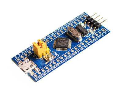
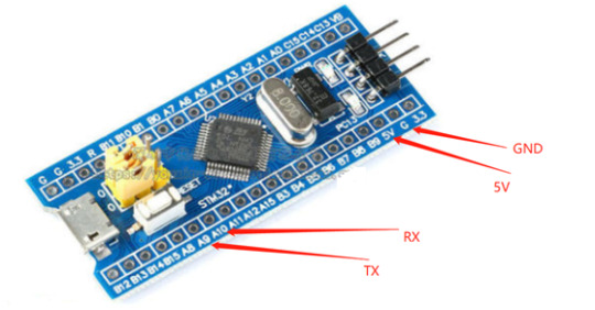
STM32F103C8T6
There are many materials and development documents about this chip on the Internet. Here is a brief introduction of this chip.
This is the development board of STM32F103C8T6, the purchase link:
https://item.taobao.com/item.htm?id=597967750760&ali_refid=a3_420434_1006:1189590055:N:jxREdm5V8MoL69LZxL%2Biz%2BQbG4S%2FtfkN:7ae5423c73cc44495581abdec5cd6265&ali_trackid=1_7ae5423c73cc44495581abdec5cd6265&spm=a230r.1.1957635.59
I'm not going to say much about this chip.The chip download code is j-link, as shown below:
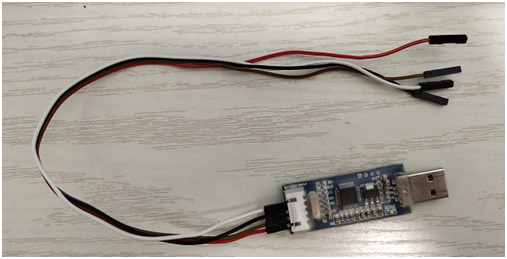
This is a simple version of j-link, only support SWD mode debugging and download, not support JTAG.But for the development of STM32 chip, SWD debugging method is enough.
Download the code to the STM32 chip
Ensure the correct wiring of j-link and STM32F103C8T6, and then the chip can be identified in the KEIL development environment:
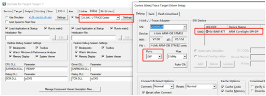
Click the download button to download the code to the chip:
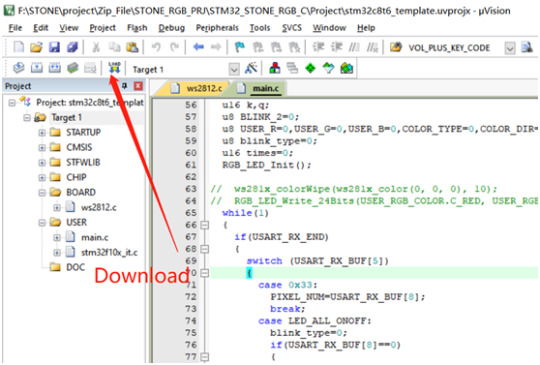
STM32 code
The buttons and text in the display screen have corresponding addresses. In this project, the addresses of the display screen components are as follows:
#define RED_COLOR 0x07
#define ICON_WHITE_ADDR 0x02
#define ICON_RED_ADDR 0x03
#define ICON_GREEN_ADDR 0x04
#define ICON_BLUE_ADDR 0x05
#define TEXT_RED_ADDR 0x07
#define TEXT_GREEN_ADDR 0x08
#define TEXT_BLUE_ADDR 0x09
#define TEXT_WHITE_ADDR 0x06
#define SWITCH_ONOFF_ADDR 0x01
#define ICON_ON 0x01
#define ICON_OFF 0x00
u8 data_send[8]= {0xA5, 0x5A, 0x05, 0x82, 0x00, 0x00, 0x00,0x00};
Data sent to the display screen should be sent according to the corresponding format:
U8 data_send[8]= {0xA5, 0x5A, 0x05, 0x82, 0x00,0x00,0x00,0x00};
Data [4]\ data[5] is the high and low order of component addresses.
Data [6]\ data[7] is the data to be displayed by the component.
The main logical code will be provided below:
#include "stm32f10x.h"
#include "usart.h"
#include "delay.h"
#include "../BOARD/ws2812/ws2812.h"
struct RGB_COLOR
{
u8 C_RED;
u8 C_GREEN;
u8 C_BLUE;
u8 C_WHITE;
u8 C_RED_FLAG;
u8 C_GREEN_FLAG;
u8 C_BLUE_FLAG;
};
#define ICON_WHITE_ADDR 0x02
#define ICON_RED_ADDR 0x03
#define ICON_GREEN_ADDR 0x04
#define ICON_BLUE_ADDR 0x05
#define TEXT_RED_ADDR 0x07
#define TEXT_GREEN_ADDR 0x08
#define TEXT_BLUE_ADDR 0x09
#define TEXT_WHITE_ADDR 0x06
#define SWITCH_ONOFF_ADDR 0x01
#define ICON_ON 0x01
#define ICON_OFF 0x00
u8 data_send[8]= {0xA5, 0x5A, 0x05, 0x82, 0x00, 0x00, 0x00,0x00};
void UART1_Send_Array(u8 send_array[],unsigned char num)
{
u8 i=0;
while(i<num)
{
USART_SendData(USART1,send_array[i]);
while( USART_GetFlagStatus(USART1,USART_FLAG_TC)!= SET);
i++;
}
}
int main(void)
{
uart_init(115200);
delay_init();
struct RGB_COLOR USER_RGB_COLOR;
USER_RGB_COLOR.C_BLUE=0;
USER_RGB_COLOR.C_GREEN=0;
USER_RGB_COLOR.C_RED=0;
USER_RGB_COLOR.C_RED_FLAG=1;
USER_RGB_COLOR.C_GREEN_FLAG=1;
USER_RGB_COLOR.C_BLUE_FLAG=1;
u16 k,q;
u8 BLINK_2=0;
u8 USER_R=0,USER_G=0,USER_B=0,COLOR_TYPE=0,COLOR_DIR=0;
u8 blink_type=0;
u16 times=0;
RGB_LED_Init();
while(1)
{
if(USART_RX_END)
{
switch (USART_RX_BUF[5])
{
case 0x33:
PIXEL_NUM=USART_RX_BUF[8];
break;
case LED_ALL_ONOFF:
blink_type=0;
if(USART_RX_BUF[8]==0)
{
data_send[5]=ICON_RED_ADDR;
data_send[7]=ICON_OFF;
UART1_Send_Array(data_send,8);
data_send[5]=TEXT_RED_ADDR;
data_send[7]=0x00;
UART1_Send_Array(data_send,8);
data_send[5]=ICON_GREEN_ADDR;
data_send[7]=ICON_OFF;
UART1_Send_Array(data_send,8);
�� data_send[5]=TEXT_GREEN_ADDR;
data_send[7]=0x00;
UART1_Send_Array(data_send,8);
data_send[5]=ICON_BLUE_ADDR;
data_send[7]=ICON_OFF;
UART1_Send_Array(data_send,8);
data_send[5]=TEXT_BLUE_ADDR;
data_send[7]=0x00;
UART1_Send_Array(data_send,8);
USER_RGB_COLOR.C_BLUE=0;
USER_RGB_COLOR.C_GREEN=0;
USER_RGB_COLOR.C_RED=0;
data_send[5]=ICON_WHITE_ADDR;
data_send[7]=ICON_OFF;
UART1_Send_Array(data_send,8);
data_send[5]=TEXT_WHITE_ADDR;
data_send[7]=0x00;
UART1_Send_Array(data_send,8);
USER_RGB_COLOR.C_WHITE=0;
}
else
{
USER_RGB_COLOR.C_BLUE=0x32;
USER_RGB_COLOR.C_GREEN=0x10;
USER_RGB_COLOR.C_RED=0x24;
USER_RGB_COLOR.C_RED_FLAG=0;
USER_RGB_COLOR.C_GREEN_FLAG=0;
USER_RGB_COLOR.C_BLUE_FLAG=0;
data_send[5]=ICON_RED_ADDR;
data_send[7]=ICON_ON;
UART1_Send_Array(data_send,8);
data_send[5]=TEXT_RED_ADDR;
data_send[7]=0x24;
UART1_Send_Array(data_send,8);
data_send[5]=ICON_GREEN_ADDR;
data_send[7]=ICON_ON;
UART1_Send_Array(data_send,8);
data_send[5]=TEXT_GREEN_ADDR;
data_send[7]=0x10;
UART1_Send_Array(data_send,8);
data_send[5]=ICON_BLUE_ADDR;
data_send[7]=ICON_ON;
UART1_Send_Array(data_send,8);
data_send[5]=TEXT_BLUE_ADDR;
data_send[7]=0x32;
UART1_Send_Array(data_send,8);
}
RGB_LED_Write_24Bits(USER_RGB_COLOR.C_RED, USER_RGB_COLOR.C_GREEN, USER_RGB_COLOR.C_BLUE);
break;
case RED_COLOR:
blink_type=0;
if(USER_RGB_COLOR.C_RED_FLAG==1)
{
if(USART_RX_BUF[8]==0)
break;
}
data_send[5]=ICON_WHITE_ADDR;
data_send[7]=ICON_OFF;
UART1_Send_Array(data_send,8);
data_send[5]=TEXT_WHITE_ADDR;
data_send[7]=0x00;
UART1_Send_Array(data_send,8);
USER_RGB_COLOR.C_WHITE=0;
data_send[5]=SWITCH_ONOFF_ADDR;
data_send[7]=ICON_ON;
UART1_Send_Array(data_send,8);
data_send[5]=ICON_RED_ADDR;
if(USART_RX_BUF[8]>0)data_send[7]=ICON_ON;
else data_send[7]=ICON_OFF;
UART1_Send_Array(data_send,8);
USER_RGB_COLOR.C_RED=USART_RX_BUF[8];
USER_RGB_COLOR.C_RED_FLAG=0;
if(USER_RGB_COLOR.C_RED==0)USER_RGB_COLOR.C_RED_FLAG=1;
if((USER_RGB_COLOR.C_RED==0x00)&&(USER_RGB_COLOR.C_GREEN==0x00)&&(USER_RGB_COLOR.C_BLUE==0x00)&&(USER_RGB_COLOR.C_WHITE==0x00))
{
data_send[5]=SWITCH_ONOFF_ADDR;
data_send[7]=ICON_OFF;
UART1_Send_Array(data_send,8);
}
RGB_LED_Write_24Bits(USER_RGB_COLOR.C_RED, USER_RGB_COLOR.C_GREEN, USER_RGB_COLOR.C_BLUE); // Red
break;
case GREEN_COLOR:
blink_type=0;
if(USER_RGB_COLOR.C_GREEN_FLAG==1)
{
if(USART_RX_BUF[8]==0)
break;
}
data_send[5]=ICON_GREEN_ADDR;
if(USART_RX_BUF[8]>0)data_send[7]=ICON_ON;
else data_send[7]=ICON_OFF;
UART1_Send_Array(data_send,8);
data_send[5]=ICON_WHITE_ADDR;
data_send[7]=ICON_OFF;
UART1_Send_Array(data_send,8);
data_send[5]=TEXT_WHITE_ADDR;
data_send[7]=0x00;
UART1_Send_Array(data_send,8);
USER_RGB_COLOR.C_WHITE=0;
data_send[5]=SWITCH_ONOFF_ADDR;
data_send[7]=ICON_ON;
UART1_Send_Array(data_send,8);
USER_RGB_COLOR.C_GREEN=USART_RX_BUF[8];
USER_RGB_COLOR.C_GREEN_FLAG=0;
if(USER_RGB_COLOR.C_GREEN==0)USER_RGB_COLOR.C_GREEN_FLAG=1;
if((USER_RGB_COLOR.C_RED==0x00)&&(USER_RGB_COLOR.C_GREEN==0x00)&&(USER_RGB_COLOR.C_BLUE==0x00)&&(USER_RGB_COLOR.C_WHITE==0x00))
{
data_send[5]=SWITCH_ONOFF_ADDR;
data_send[7]=ICON_OFF;
UART1_Send_Array(data_send,8);
}
RGB_LED_Write_24Bits(USER_RGB_COLOR.C_RED, USER_RGB_COLOR.C_GREEN, USER_RGB_COLOR.C_BLUE); // Green
break;
case BLUE_COLOR:
blink_type=0;
if(USER_RGB_COLOR.C_BLUE_FLAG==1)
{
if(USART_RX_BUF[8]==0)
break;
}
data_send[5]=ICON_BLUE_ADDR;
if(USART_RX_BUF[8]>0)data_send[7]=ICON_ON;
else data_send[7]=ICON_OFF;
UART1_Send_Array(data_send,8);
data_send[5]=ICON_WHITE_ADDR;
data_send[7]=ICON_OFF;
UART1_Send_Array(data_send,8);
data_send[5]=TEXT_WHITE_ADDR;
data_send[7]=0x00;
UART1_Send_Array(data_send,8);
USER_RGB_COLOR.C_WHITE=0;
data_send[5]=SWITCH_ONOFF_ADDR;
data_send[7]=ICON_ON;
UART1_Send_Array(data_send,8);
USER_RGB_COLOR.C_BLUE=USART_RX_BUF[8];
USER_RGB_COLOR.C_BLUE_FLAG=0;
if(USER_RGB_COLOR.C_BLUE==0)USER_RGB_COLOR.C_BLUE_FLAG=1;
if((USER_RGB_COLOR.C_RED==0x00)&&(USER_RGB_COLOR.C_GREEN==0x00)&&(USER_RGB_COLOR.C_BLUE==0x00)&&(USER_RGB_COLOR.C_WHITE==0x00))
{
data_send[5]=SWITCH_ONOFF_ADDR;
data_send[7]=ICON_OFF;
UART1_Send_Array(data_send,8);
}
RGB_LED_Write_24Bits(USER_RGB_COLOR.C_RED, USER_RGB_COLOR.C_GREEN, USER_RGB_COLOR.C_BLUE); // Blue
break;
case WHITE_COLOR:
blink_type=0;
data_send[5]=ICON_WHITE_ADDR;
if(USART_RX_BUF[8]>0)data_send[7]=ICON_ON;
else data_send[7]=ICON_OFF;
UART1_Send_Array(data_send,8);
data_send[5]=ICON_RED_ADDR;
data_send[7]=ICON_OFF;
UART1_Send_Array(data_send,8);
data_send[5]=TEXT_RED_ADDR;
data_send[7]=0x00;
UART1_Send_Array(data_send,8);
data_send[5]=ICON_GREEN_ADDR;
data_send[7]=ICON_OFF;
UART1_Send_Array(data_send,8);
data_send[5]=TEXT_GREEN_ADDR;
data_send[7]=0x00;
UART1_Send_Array(data_send,8);
data_send[5]=ICON_BLUE_ADDR;
data_send[7]=ICON_OFF;
UART1_Send_Array(data_send,8);
data_send[5]=TEXT_BLUE_ADDR;
data_send[7]=0x00;
UART1_Send_Array(data_send,8);
USER_RGB_COLOR.C_BLUE=0;
USER_RGB_COLOR.C_GREEN=0;
USER_RGB_COLOR.C_RED=0;
USER_RGB_COLOR.C_RED_FLAG=1;
USER_RGB_COLOR.C_GREEN_FLAG=1;
USER_RGB_COLOR.C_BLUE_FLAG=1;
data_send[5]=SWITCH_ONOFF_ADDR;
data_send[7]=ICON_ON;
UART1_Send_Array(data_send,8);
USER_RGB_COLOR.C_WHITE=USART_RX_BUF[8];
if((USER_RGB_COLOR.C_RED==0x00)&&(USER_RGB_COLOR.C_GREEN==0x00)&&(USER_RGB_COLOR.C_BLUE==0x00)&&(USER_RGB_COLOR.C_WHITE==0x00))
{
data_send[5]=SWITCH_ONOFF_ADDR;
data_send[7]=ICON_OFF;
UART1_Send_Array(data_send,8);
}
RGB_LED_Write_24Bits(USER_RGB_COLOR.C_WHITE, USER_RGB_COLOR.C_WHITE, USER_RGB_COLOR.C_WHITE);
break;
case BLINK1:
blink_type=1;
data_send[5]=ICON_RED_ADDR;
data_send[7]=ICON_OFF;
UART1_Send_Array(data_send,8);
data_send[5]=TEXT_RED_ADDR;
data_send[7]=0x00;
UART1_Send_Array(data_send,8);
data_send[5]=ICON_GREEN_ADDR;
data_send[7]=ICON_OFF;
UART1_Send_Array(data_send,8);
data_send[5]=TEXT_GREEN_ADDR;
data_send[7]=0x00;
UART1_Send_Array(data_send,8);
data_send[5]=ICON_BLUE_ADDR;
data_send[7]=ICON_OFF;
UART1_Send_Array(data_send,8);
data_send[5]=TEXT_BLUE_ADDR;
data_send[7]=0x00;
UART1_Send_Array(data_send,8);
USER_RGB_COLOR.C_BLUE=0;
USER_RGB_COLOR.C_GREEN=0;
USER_RGB_COLOR.C_RED=0;
data_send[5]=ICON_WHITE_ADDR;
data_send[7]=ICON_OFF;
UART1_Send_Array(data_send,8);
data_send[5]=TEXT_WHITE_ADDR;
data_send[7]=0x00;
UART1_Send_Array(data_send,8);
USER_RGB_COLOR.C_WHITE=0;
data_send[5]=SWITCH_ONOFF_ADDR;
data_send[7]=ICON_ON;
UART1_Send_Array(data_send,8);
break;
case BLINK2:
blink_type=2;
data_send[5]=ICON_RED_ADDR;
data_send[7]=ICON_OFF;
UART1_Send_Array(data_send,8);
data_send[5]=TEXT_RED_ADDR;
data_send[7]=0x00;
UART1_Send_Array(data_send,8);
data_send[5]=ICON_GREEN_ADDR;
data_send[7]=ICON_OFF;
UART1_Send_Array(data_send,8);
data_send[5]=TEXT_GREEN_ADDR;
data_send[7]=0x00;
UART1_Send_Array(data_send,8);
data_send[5]=ICON_BLUE_ADDR;
data_send[7]=ICON_OFF;
UART1_Send_Array(data_send,8);
data_send[5]=TEXT_BLUE_ADDR;
data_send[7]=0x00;
UART1_Send_Array(data_send,8);
USER_RGB_COLOR.C_BLUE=0;
USER_RGB_COLOR.C_GREEN=0;
USER_RGB_COLOR.C_RED=0;
data_send[5]=ICON_WHITE_ADDR;
data_send[7]=ICON_OFF;
UART1_Send_Array(data_send,8);
data_send[5]=TEXT_WHITE_ADDR;
data_send[7]=0x00;
UART1_Send_Array(data_send,8);
USER_RGB_COLOR.C_WHITE=0;
data_send[5]=SWITCH_ONOFF_ADDR;
data_send[7]=ICON_ON;
UART1_Send_Array(data_send,8);
break;
case BLINK3:
blink_type=3;
data_send[5]=ICON_RED_ADDR;
data_send[7]=ICON_OFF;
UART1_Send_Array(data_send,8);
data_send[5]=TEXT_RED_ADDR;
data_send[7]=0x00;
UART1_Send_Array(data_send,8);
data_send[5]=ICON_GREEN_ADDR;
data_send[7]=ICON_OFF;
UART1_Send_Array(data_send,8);
data_send[5]=TEXT_GREEN_ADDR;
data_send[7]=0x00;
UART1_Send_Array(data_send,8);
data_send[5]=ICON_BLUE_ADDR;
data_send[7]=ICON_OFF;
UART1_Send_Array(data_send,8);
data_send[5]=TEXT_BLUE_ADDR;
data_send[7]=0x00;
UART1_Send_Array(data_send,8);
USER_RGB_COLOR.C_BLUE=0;
USER_RGB_COLOR.C_GREEN=0;
USER_RGB_COLOR.C_RED=0;
// USER_RGB_COLOR.C_RED_FLAG=1;
// USER_RGB_COLOR.C_GREEN_FLAG=1;
// USER_RGB_COLOR.C_BLUE_FLAG=1;
data_send[5]=ICON_WHITE_ADDR;
data_send[7]=ICON_OFF;
UART1_Send_Array(data_send,8);
data_send[5]=TEXT_WHITE_ADDR;
data_send[7]=0x00;
UART1_Send_Array(data_send,8);
USER_RGB_COLOR.C_WHITE=0;
data_send[5]=SWITCH_ONOFF_ADDR;
data_send[7]=ICON_ON;
UART1_Send_Array(data_send,8);
break;
case BLINK4:
blink_type=4;
data_send[5]=ICON_RED_ADDR;
data_send[7]=ICON_OFF;
UART1_Send_Array(data_send,8);
data_send[5]=TEXT_RED_ADDR;
data_send[7]=0x00;
UART1_Send_Array(data_send,8);
data_send[5]=ICON_GREEN_ADDR;
data_send[7]=ICON_OFF;
UART1_Send_Array(data_send,8);
data_send[5]=TEXT_GREEN_ADDR;
data_send[7]=0x00;
UART1_Send_Array(data_send,8);
data_send[5]=ICON_BLUE_ADDR;
data_send[7]=ICON_OFF;
UART1_Send_Array(data_send,8);
data_send[5]=TEXT_BLUE_ADDR;
data_send[7]=0x00;
UART1_Send_Array(data_send,8);
USER_RGB_COLOR.C_BLUE=0;
USER_RGB_COLOR.C_GREEN=0;
USER_RGB_COLOR.C_RED=0;
data_send[5]=ICON_WHITE_ADDR;
data_send[7]=ICON_OFF;
UART1_Send_Array(data_send,8);
data_send[5]=TEXT_WHITE_ADDR;
data_send[7]=0x00;
UART1_Send_Array(data_send,8);
USER_RGB_COLOR.C_WHITE=0;
data_send[5]=SWITCH_ONOFF_ADDR;
data_send[7]=ICON_ON;
UART1_Send_Array(data_send,8);
break;
default:
USART_RX_END=0;
USART_RX_STA=0;
break;
}
USART_RX_STA=0;
USART_RX_END=0;
}
else
{
if(blink_type==1)
{
times++;
if(times>=14)
{
times=0;
if(COLOR_DIR==0)
{
if(COLOR_TYPE==0)
{
USER_R++;
USER_G=0;
USER_B=0;
}
else if(COLOR_TYPE==1)
{
USER_R=0;
USER_G++;
USER_B=0;
}
else if(COLOR_TYPE==2)
{
USER_R=0;
USER_G=0;
USER_B++;
}
else if(COLOR_TYPE==3)
{
USER_R++;
USER_G++;
USER_B=0;
}
else if(COLOR_TYPE==4)
{
USER_R=0;
USER_G++;
USER_B++;
}
else if(COLOR_TYPE==5)
{
USER_R++;
USER_G=0;
USER_B++;
}
if((USER_R>=250)||(USER_G>=250)||(USER_B>=250))
{
COLOR_DIR=1;
}
}
else
{
if(COLOR_TYPE==0)
{
USER_R--;
USER_G=0;
USER_B=0;
}
else if(COLOR_TYPE==1)
{
USER_R=0;
USER_G--;
USER_B=0;
}
else if(COLOR_TYPE==2)
{
USER_R=0;
USER_G=0;
USER_B--;
}
else if(COLOR_TYPE==3)
{
USER_R--;
USER_G--;
USER_B=0;
}
else if(COLOR_TYPE==4)
{
USER_R=0;
USER_G--;
USER_B--;
}
else if(COLOR_TYPE==5)
{
USER_R--;
USER_G=0;
USER_B--;
}
if((USER_R==0x02)||(USER_G==0x02)||(USER_B==0x02))
{
COLOR_DIR=0;
COLOR_TYPE++;
if(COLOR_TYPE>5)
COLOR_TYPE=0;
}
}
RGB_LED_Write_24Bits(USER_R,USER_G,USER_B);
}
delay_ms(1);
}
else if(blink_type==2)
{
k++;
if(k>=150)
{
k=0;
q=200;
{
BLINK_2++;
if(BLINK_2>8)BLINK_2=0;
}
if(BLINK_2==0)
RGB_LED_Write_24Bits(q,0,0);
else if(BLINK_2==1)
RGB_LED_Write_24Bits(0,q,0);
else if(BLINK_2==2)
RGB_LED_Write_24Bits(0,0,q);
else if(BLINK_2==3)
RGB_LED_Write_24Bits(q,q,0);
else if(BLINK_2==4)
RGB_LED_Write_24Bits(0,q,q);
else if(BLINK_2==5)
RGB_LED_Write_24Bits(q,0,q);
else if(BLINK_2==6)
RGB_LED_Write_24Bits(q-100,q,0);
else if(BLINK_2==7)
RGB_LED_Write_24Bits(0,q-80,q);
else if(BLINK_2==8)
RGB_LED_Write_24Bits(q,0,q-120);
else if(BLINK_2==9)
RGB_LED_Write_24Bits(40,q-100,q-70);
else if(BLINK_2==10)
RGB_LED_Write_24Bits(q,100,q-80);
}
delay_ms(1);
}
else if(blink_type==3)
{
k++;
if(k>=1000)
{
k=0;
{
BLINK_2++;
if(BLINK_2>5)BLINK_2=0;
}
{
if(BLINK_2==0)
RGB_LED_Write_24Bits(q,0,0);
else if(BLINK_2==1)
RGB_LED_Write_24Bits(0,q,0);
else if(BLINK_2==2)
RGB_LED_Write_24Bits(0,0,q);
else if(BLINK_2==3)
RGB_LED_Write_24Bits(q,q,0);
else if(BLINK_2==4)
RGB_LED_Write_24Bits(0,q,q);
else if(BLINK_2==5)
RGB_LED_Write_24Bits(q,0,q);
}
}
delay_ms(1);
}
else if(blink_type==4)
{
k++;
if(k>=500)
{
k=0;
q=0;
BLINK_2++;
if(BLINK_2>5)BLINK_2=0;
}
q++;
if(q>=250)q=0;
if(BLINK_2==0)
RGB_LED_Write_24Bits(q,0,0);
else if(BLINK_2==1)
RGB_LED_Write_24Bits(0,q,0);
else if(BLINK_2==2)
RGB_LED_Write_24Bits(0,0,q);
else if(BLINK_2==3)
RGB_LED_Write_24Bits(q,q,0);
else if(BLINK_2==4)
RGB_LED_Write_24Bits(0,q,q);
else if(BLINK_2==5)
RGB_LED_Write_24Bits(q,0,q);
delay_ms(1);
}
else
{
}
}
}
}
Finally, the code is downloaded into the STM32 chip, and the completed circuit board is connected to the display screen, and the power supply is guaranteed to be stable. Then the brightness and color of the RGB lamp can be controlled through the STONE display module.
The final hardware connection diagram
Running effect

0 notes
Text
TL072QDREP
TL072QDREP is a JFET- input operational amplifier with low input bias and offset currents and fast slew rate, i.e., 13V/μs. Slew rate is defined because the maximum rate at which an amplifier can answer a sudden glitch within the input level. Moreover, it's low harmonic distortion; for that reason, it's ideal to use in audio preamplifier applications.

Some of the important facts about the module TL072QDREP are as under:
Low input power
It has low input bias and offset currents.
It features a harmonic distortion of around 0.003%. The important factor is that it ensures the standard of output.
The slew rate of about 13V/μs.
It has high input impedance. For a perfect amplifier, input impedance should be infinite. The upper input impedance of the module TL072QDREP ensures the best behavior of the module.
Module TL072QDREP offers the benefits that are desired in many audio applications. Module TL072QDREP could be a suitable op-amp for audio applications, having higher gain and better bandwidth. In the high input stage, giving verily low bias currents, the only drawback of the module TL072QDREP is its offset voltage limitation. TL072QDREP's Input offset voltage isn't particularly low and can be temperature sensitive.
NE5534 is another module that will replace TL072QDREP. The NE5534 is additionally an improved' part compared to the 741 benchmarks, but it has been improved in alternative ways. With a low noise bipolar input stage and plenty of bandwidth. Its bandwidth is tailored to the chip's compensation capacitor for sale being required externally. The user can choose where to pitch the dominant pole or select more complex compensation schemes. It's an output stage that will source plenty more current than the TL072 families. However, a challenge is that the low noise/wide bandwidth features are achieved by running moderate gain bipolar transistors within the input stage at significant DC currents. Therefore the bias currents flowing in its input pins are vast.
The module TL072QDREP encompasses many applications because of its efficient parameters. The most straightforward and demanding application is an Oscilloscope that amplifies the signal for better visibility and reading the voltage. Another essential application of module TL072QDREP is Audio mixers. Audio mixers take various inputs via an appropriate resistor to virtual earth points, mixing different sounds and audio signals. Another advantage of the module is sound reproduction (Hi-Fi). The term above refers to the high-quality reproduction of sound with lower latency, accuracy in 3D sound, and more cross-browser compatibility. Audio amplifiers have Inaudible noise and distortion and neutral frequency response within the human hearing range.
#Lm2596s | Amaxchip#Stm32f103c8t6#Capacitors For Sale#Mlcc Capacitor#Electronic Wholesale Distributors#electrical parts online
0 notes