#ToF sensor
Explore tagged Tumblr posts
Visit Tumblr Blog
Explore Tumblr blogs with no restrictions, modern design and the best experience.
Last Seen Tumblr Blogs


Fun Fact
Post activity is at the highest at 4:00 pm EDT; notes peak at 10:00 pm EDT.
Text
https://www.futureelectronics.com/p/semiconductors--analog--sensors--time-off-flight-sensors/vl6180xv0nr-1-stmicroelectronics-5053972
What is a Time of Flight Sensor, Time-of-flight sensor vs ultrasonic,
VL6180X Series 3 V Proximity and Ambient Light Sensing (ALS) Module - LGA-12
#STMicroelectronics#VL6180XV0NR/1#Sensors#Time of Flight (ToF) Sensors#ultrasonic#Digital image sensors#ToF sensor#3D Depth Camera#Camera image#Laser-based time-of-flight cameras#vehicle monitoring#Time-of-Flight imagers
1 note
·
View note
Text
STMicroelectronics launches next-generation multi-zone time-of-flight sensor
December 15, 2023 /SemiMedia/ — STMicroElectronics recently released its latest generation 8×8 multi-zone time-of-flight (ToF) ranging sensor, VL53L8CX, which offers a range of improvements including greater ambient-light immunity, lower power consumption, and enhanced optics. ST’s direct-ToF sensors combine a 940nm vertical cavity surface emitting laser (VCSEL), a multizone SPAD (single-photon…

View On WordPress
#electronic components news#Electronic components supplier#Electronic parts supplier#STMicroelectronics#ToF sensor#VL53L8CX
0 notes
Text
https://www.futureelectronics.com/p/semiconductors--analog--sensors--time-off-flight-sensors/vl6180xv0nr-1-stmicroelectronics-4051964
Imaging camera system, RF-modulated light sources Range gated imagers
VL6180X Series 3 V Proximity and Ambient Light Sensing (ALS) Module - LGA-12
#Sensors#Time of Flight (ToF) Sensors#VL6180XV0NR/1#STMicroelectronics#imaging camera system#RF-modulated light sources Range gated imagers#Laser-based#Real-time simulation#3D Depth Camera#Range gated imagers
1 note
·
View note
Text
https://www.futureelectronics.com/p/semiconductors--analog--sensors--time-off-flight-sensors/vl6180xv0nr-1-stmicroelectronics-4173292
Time of Flight 3D camera developed, Light Sensing, robot navigation
VL6180X Series 3 V Proximity and Ambient Light Sensing (ALS) Module - LGA-12
#STMicroelectronics#VL6180XV0NR/1#Sensors#Time of Flight (ToF) Sensors#3D camera developed#Light Sensing#robot navigation#Lock-in#camera#Object detection#RF-module light sources#Real-time simulation#phone#vehicle monitoring#people counting
1 note
·
View note
Text
Arduino Plug and Make Kit: Abstandskontrolle mit Alarmfunktion

In diesem Beitrag erfährst du Schritt-für-Schritt, wie man eine Abstandskontrolle mit Alarmfunktion mit dem Arduino Plug and Make Kit aufbaut und programmiert. Das neue Arduino Plug and Make Kit habe ich dir bereits im gleichnamigen Beitrag Arduino Plug and Make Kit: Was ist drin und wie benutzt man es? vorgestellt. https://youtu.be/YL-enMuAMBc Das Arduino Plug and Make Kit bekommst du derzeit für knapp 90€ inkl. Versandkosten im offiziellen Shop. Aus diesem Kit verwenden wir den Arduino UNO R4 WiFi, den Laser Distanzsensor, den Piezo Buzzer, das 8fach LED Modul sowie den Rotary Encoder. Zusätzlich benötigen wir noch die Modulino Base, ein paar Schrauben & Muttern sowie die Qwiic Anschlusskabel. Das alles ist im Kit enthalten, du benötigst quasis nurnoch deinen PC und einen kleinen Kreuzschraubendreher.

Arduino UNO R4 WiFi
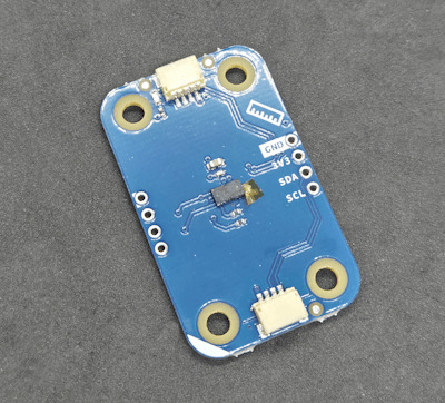
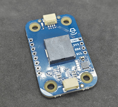
ToF - Distance Sensor
Buzzer

8fach LED Modul
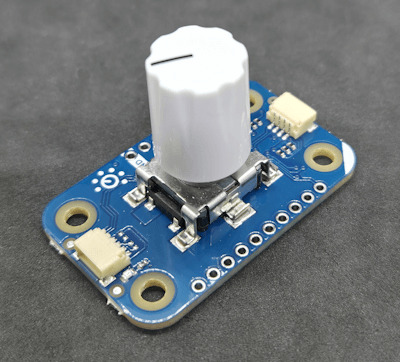
Rotary Encoder
Wie soll das kleine Projekt funktionieren?
Über den Distanzsensor messen wir dauerhaft einen Abstand zu einem Gegenstand (Wand, Türrahmen etc.) wenn dieser Wert unterschritten wird, dann wird ein Alarm (akustisch und visuell) ausgegeben. Über den Rotary Encoder und der 8x12 LED Matrix vom Arduino UNO R4 WiFi stellen wir den Abstand ein. Dabei wird, wenn wir eine Klick-Aktion am Rotary Encoder ausführen, der aktuelle Wert auf der Matrix ausgegeben.
Benötigte Ressourcen für den Aufbau
Für den Aufbau der Schaltung benötigst du: - einen Arduino UNO R4 WiFi, - ein USB-C Datenkabel, - ein ToF / Laser Distanzsensor, - ein Rotary Encoder, - ein 8fach LED Modul, - ein Piezo Buzzer, sowie - ein paar Schrauben und - einen kleinen Kreuzschraubendreher

Arduino Plug and Make Kit - Komponenten für das Alarmprojekt Ausgenommen vom Kreuzschraubendreher ist alles im Arduino Plug and Make Kit enthalten!
Programmieren der Modulino Sensoren / Aktoren in der Ardino IDE
Das Kit ist ausgelegt, um in der Arduino IDE programmiert zu werden. Du musst jedoch zuvor den Boardtreiber für den Arduino UNO R4 WiFi und die Bibliothek für die Modulino Sensoren / Aktoren installieren.

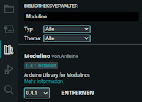
Zu der Bibliothek Modulino erhältst du zu jedem Sensor / Aktor aus diesem Kit ein ausführliches Beispiel und in der offiziellen Dokumentation nochmal viel mehr Informationen. Programm - Durchgangsalarm mit dem Arduino Plug and Make KitHerunterladen Schritt 1 - Importieren der Bibliotheken und erzeugen der Objektinstanzen Im ersten Schritt importieren wir die benötigten Bibliotheken für das Projekt. (Zur Vorbereitung hatten wir bereits die Modulino Bibliothek installiert.) //Bibliothek zum steuern / auslesen //der Modulino Sensoren / Aktoren #include //Bibliotheken zum steuern der //8x12 LED Matrix am Arduino UNO R4 WiFi #include "ArduinoGraphics.h" #include "Arduino_LED_Matrix.h" Anschließend erzeugen wir uns die Objektinstanzen für unser Projekt. //Objektinstanz der LED-Matrix ArduinoLEDMatrix matrix; //Objektinstanzen der Sensoren / Aktoren ModulinoDistance distance; ModulinoPixels leds; ModulinoKnob knob; ModulinoBuzzer buzzer; Schritt 2 - Initialisieren der Kommunikation mit den Sensoren / Aktoren Nachdem die benötigten Bibliotheken installiert und die Objekte erzeugt wurden, müssen wir die I2C Kommunikation starten. Dazu müssen wir bei den Modulinos lediglich die Funktion "begin" aufrufen. Dieses macht die verwendung dieser Module sehr einfach und komfortabel. void setup() { //beginn der seriellen Kommunikation Serial.begin(9600); //beginn der Kommunikation mit der LED-Matrix matrix.begin(); //Vorbereiten der Kommunikation mit den Modulino //Sensoren / Aktoren Modulino.begin(); //Initialisieren der I2C Kommunikation mit den //Sensoren / Aktoren distance.begin(); leds.begin(); knob.begin(); buzzer.begin(); //Startwert des Rotary Encoders / Knob auf 0 setzen. knob.set(0); } Zusätzlich setze ich den Wert des Rotary Encoders auf 0. Schritt 3 - Auslesen der Sensorwerte und erzeugen des Alarms Im dritten Schritt lesen wir in der Funktion "loop" zunächst den Wert des Rotary Encoders aus und multiplizieren diesen mit 10. Damit müssen wir nicht so viele Umdrehungen machen damit ein Abstand eingestellt werden kann, wenn du kleine Schritte benötigst dann musst du diesen Wert anpassen. //lesen des aktuellen Wertes vom Rotary Encoder //der Wert wird mit 10 multipliziert und abgespeichert int16_t distanceForAlarm = knob.get() * 10; Wenn der Rotary Encoder gedrückt wird, können wir eine zusätzliche Aktion ausführen, in diesem Fall wird der Wert auf der 8x12 LED Matrix angezeigt. //Wenn der Rotary Encoder gedrückt wird, dann... if (knob.isPressed()) { //Aufrufen der Funktion zum Anzeigen des aktuellen //wertes des Rotary Encoder. displayKnobValue(distanceForAlarm); } Wenn der Distanzsensor erkannt wurde, dann lesen wir einen Messwert und vergleichen diesen mit dem eingestellten Abstand vom Rotary Encoder. if (distance.available()) { //Messwert abrufen und abspeichern int measure = distance.get(); //Wenn der messwert kleiner als der abgespeicherte //Wert für den Alarm ist, dann... if (measure < distanceForAlarm) { //Ausgeben des Textes "Alarm" auf der seriellen Schnittstelle Serial.println("Alarm"); //anzeigen eines visuellen Alarms über das 8fach LED Modul visualAlarm(); //ausgeben eines akustischen Alarms über das Piezo Buzzer Modul soundAlarm(); } } Am Ende legen wir noch eine kleine Pause von 20 Millisekunden ein. //eine kleine Pause von 20 ms. delay(20); Schritt 3.1 - Funktion "displayKnobValue" Die Funktion displayKnobValue zeigt den Wert des Übergebenen Parameters auf der 8x12 LED Matrix an. Sollte jedoch der Wert kleiner 0 sein, so wird eine Fehlermeldung angezeigt. /Funktion zum anzeigen eines Textes auf der //LED-Matrix. void displayKnobValue(int16_t value) { matrix.beginDraw(); matrix.stroke(0xFFFFFFFF); matrix.textScrollSpeed(50); String message = "-undefined- "; //Wenn der Wert kleiner 0 ist, dann... if (value < 0) { //erzeugen einer kleinen Fehlermeldung message = "err: val < 0"; } else { //Wenn der wert größer 0 ist, dann müssen wir //eine 12 Zeichen lange Zeichenkette erzeugen. int valueLength = String(value).length(); int partLength = (12 - valueLength) / 2; String part = ""; for (int s = 0; s < partLength; s++) { part += " "; } message = part + String(value) + part; } //ablegen der erstellten Zeichenkette in das Char-Array char text = ""; message.toCharArray(text, 13); //Ausgeben des Textes auf der LED-Matrix //Schriftgröße 4x6 matrix.textFont(Font_4x6); matrix.beginText(0, 1, 0xFFFFFF); matrix.println(text); matrix.endText(SCROLL_LEFT); matrix.endDraw(); } Schritt 3.2 - Funktion "visualAlarm" Die Funktion visualAlarm lässt die LEDs im 25ms. Intervall aufleuchten. //Funktion zum erzeugen eines visuellen Alarms mit //dem 8fach LED Modul. Die LEDs blinken im 25ms. Takt void visualAlarm() { setLEDsStatus(true); delay(25); setLEDsStatus(false); delay(25); } //Funktion zum setzen der LEDs. //Als Parameter wird der erwartete Status übergeben. void setLEDsStatus(bool on) { //Schleife über die LEDs for (int i = 0; i < 8; i++) { //Wenn die LEDs aktiviert werden sollen, dann ist //die Helligkeit auf 100 ansonsten auf 0 leds.set(i, RED, on ? 100 : 0); } //nachdem alle LEDs konfiguriert wurden, dann werden //diese Daten ausgeliefert / angezeigt. leds.show(); } Schritt 3.3 - Funktion "soundAlarm" Mit der Funktion soundAlarm wird der Piezo Buzzer angesteuert und dieser erzeugt einen hellen Ton als zusätzlichen Signal. //Funktion zum erzeugen eines Tones auf //dem Piezo Buzzer Moduls. void soundAlarm() { //die Frequenz des Tones int frequency = 440; //die Dauer int duration = 1000; //erzeugen des Tones buzzer.tone(frequency, duration); delay(50); //abschalten des Tones buzzer.tone(0, duration); delay(25); } Fertiges Projekt - Durchgangsalarm mit dem Arduino Plug and Make Kit Hier nun das fertige Projekt zum kopieren. //Bibliothek zum steuern / auslesen //der Modulino Sensoren / Aktoren #include //Bibliotheken zum steuern der //8x12 LED Matrix am Arduino UNO R4 WiFi #include "ArduinoGraphics.h" #include "Arduino_LED_Matrix.h" //Objektinstanz der LED-Matrix ArduinoLEDMatrix matrix; //Objektinstanzen der Sensoren / Aktoren ModulinoDistance distance; ModulinoPixels leds; ModulinoKnob knob; ModulinoBuzzer buzzer; void setup() { //beginn der seriellen Kommunikation Serial.begin(9600); //beginn der Kommunikation mit der LED-Matrix matrix.begin(); //Vorbereiten der Kommunikation mit den Modulino //Sensoren / Aktoren Modulino.begin(); //Initialisieren der I2C Kommunikation mit den //Sensoren / Aktoren distance.begin(); leds.begin(); knob.begin(); buzzer.begin(); //Startwert des Rotary Encoders / Knob auf 0 setzen. knob.set(0); } void loop() { //lesen des aktuellen Wertes vom Rotary Encoder //der Wert wird mit 10 multipliziert und abgespeichert int16_t distanceForAlarm = knob.get() * 10; //Wenn der Rotary Encoder gedrückt wird, dann... if (knob.isPressed()) { //Aufrufen der Funktion zum Anzeigen des aktuellen //wertes des Rotary Encoder. displayKnobValue(distanceForAlarm); } //Wenn ein ToF Sensor verfügbar ist, dann... if (distance.available()) { //Messwert abrufen und abspeichern int measure = distance.get(); //Wenn der messwert kleiner als der abgespeicherte //Wert für den Alarm ist, dann... if (measure < distanceForAlarm) { //Ausgeben des Textes "Alarm" auf der seriellen Schnittstelle Serial.println("Alarm"); //anzeigen eines visuellen Alarms über das 8fach LED Modul visualAlarm(); //ausgeben eines akustischen Alarms über das Piezo Buzzer Modul soundAlarm(); } } //eine kleine Pause von 20 ms. delay(20); } //Funktion zum anzeigen eines Textes auf der //LED-Matrix. void displayKnobValue(int16_t value) { matrix.beginDraw(); matrix.stroke(0xFFFFFFFF); matrix.textScrollSpeed(50); String message = "-undefined- "; //Wenn der Wert kleiner 0 ist, dann... if (value < 0) { //erzeugen einer kleinen Fehlermeldung message = "err: val < 0"; } else { //Wenn der wert größer 0 ist, dann müssen wir //eine 12 Zeichen lange Zeichenkette erzeugen. int valueLength = String(value).length(); int partLength = (12 - valueLength) / 2; String part = ""; for (int s = 0; s < partLength; s++) { part += " "; } message = part + String(value) + part; } //ablegen der erstellten Zeichenkette in das Char-Array char text = ""; message.toCharArray(text, 13); //Ausgeben des Textes auf der LED-Matrix //Schriftgröße 4x6 matrix.textFont(Font_4x6); matrix.beginText(0, 1, 0xFFFFFF); matrix.println(text); matrix.endText(SCROLL_LEFT); matrix.endDraw(); } //Funktion zum erzeugen eines visuellen Alarms mit //dem 8fach LED Modul. Die LEDs blinken im 25ms. Takt void visualAlarm() { setLEDsStatus(true); delay(25); setLEDsStatus(false); delay(25); } //Funktion zum erzeugen eines Tones auf //dem Piezo Buzzer Moduls. void soundAlarm() { //die Frequenz des Tones int frequency = 440; //die Dauer int duration = 1000; //erzeugen des Tones buzzer.tone(frequency, duration); delay(50); //abschalten des Tones buzzer.tone(0, duration); delay(25); } //Funktion zum setzen der LEDs. //Als Parameter wird der erwartete Status übergeben. void setLEDsStatus(bool on) { //Schleife über die LEDs for (int i = 0; i < 8; i++) { //Wenn die LEDs aktiviert werden sollen, dann ist //die Helligkeit auf 100 ansonsten auf 0 leds.set(i, RED, on ? 100 : 0); } //nachdem alle LEDs konfiguriert wurden, dann werden //diese Daten ausgeliefert / angezeigt. leds.show(); } Read the full article
0 notes
Text
The Time-of-Flight (TOF) Sensor Market is growing at a CAGR of 21.07% over the next 5 years. Texas Instruments Incorporated, STMicroelectronics NV, Infineon Technologies AG, Panasonic Corporation, Sony Corporation are the major companies operating in Time-of-Flight (TOF) Sensor Market.
#Time-of-Flight (TOF) Sensor Market#Time-of-Flight (TOF) Sensor Market Size#Time-of-Flight (TOF) Sensor Market Share#Time-of-Flight (TOF) Sensor Market Analysis#Time-of-Flight (TOF) Sensor Market Trends#Time-of-Flight (TOF) Sensor Market Report#Time-of-Flight (TOF) Sensor Market Research#Time-of-Flight (TOF) Sensor Industry#Time-of-Flight (TOF) Sensor Industry Report
0 notes
Text
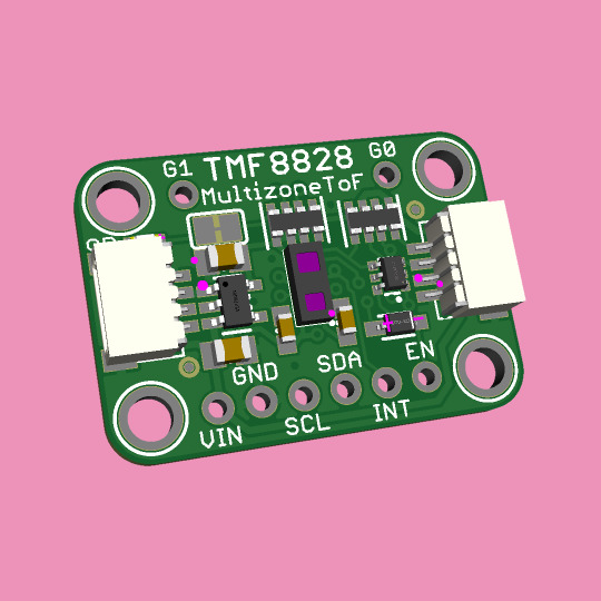
TMS8828 multi-zone time-of-flight sensor from ams OSRAM 🔍🤖🌐
We stock many ST VL5 series ToF sensors (https://www.adafruit.com/search?q=VL5), but it's always a good idea to peek at what else is available on the market. Here's a multi-zone Time of Flight sensor from ams OSRAM - the TMF8828 (https://www.digikey.com/en/products/detail/ams-osram-usa-inc/TMF8828-1AM/16285671) with 8x8 zones and up to 5 meters detection. Here's a quick QT breakout for this sensor and the support circuitry so we can try it out. Coming soon.
#adafruit#timeofflight#amsOSRAM#tmf8828#multizone#tofsensor#sensorstock#detectiontech#qtbreakout#quicktest#electronics#sensortechnology#distancemeasurement
5 notes
·
View notes
Text
Buy an iPhone 14 Pro Max 5G 128GB from Spectronic UK at an Affordable Price
Spectronic UK is a top-rated e-commerce store that specializes in offering the latest Apple phones. We take pride in providing our customers with a wide range of phones with advanced features at highly competitive prices. You can order the iPhone 14 Pro Max 5G with 128GB of storage from our online store and get it at the best price.
The following specifications are mentioned below:
Internal Memory- 128GB 6GB RAM
📷Main Camera- Triple [48 MP, f/1.8, 24mm (wide), 1/1.28″, 1.22µm, dual pixel PDAF, sensor-shift OIS, 12 MP, f/2.8, 77mm (telephoto), 1/3.5″, PDAF, OIS, 3x optical zoom, 12 MP, f/2.2, 13mm, 120˚ (ultrawide), 1/2.55″, 1.4µm, dual pixel PDAF, TOF 3D LiDAR scanner (depth)]
📷Selfie Camera- 12 MP, f/1.9, 23mm (wide), 1/3.6″, PDAF, OIS (unconfirmed) SL 3D, (depth/biometrics sensor)
🔋Battery- Li-Ion 4323 mAh, non-removable (16.68 Wh)
Colour- Deep Purple
In The Box- The Phone, USB Type-C to Lightning Cable, Documentation, Apple Sticker.
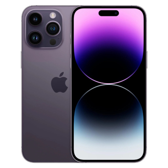
Experience the ease and convenience of online shopping with Spectronic UK by visiting our website and placing your order now!
2 notes
·
View notes
Text
0 notes
Text
https://www.laserfocusworld.com/test-measurement/article/55253453/the-battle-of-lidar-sensor-technologies-fmcw-vs-tof

FMCW LiDAR technology has the potential to "see" through walls to some extent, primarily by detecting the reflected signals from objects or materials behind a wall, depending on the wall's composition and thickness. Here are some key points regarding this application:
Material Penetration: FMCW LiDAR can penetrate certain materials better than traditional LiDAR systems, especially if the walls are made of less dense materials like drywall or wood. However, it may struggle with more solid materials like concrete or metal.
Detection of Objects: By analyzing the reflected signals, FMCW LiDAR can help identify the presence of objects behind walls, which could be useful in various applications, such as search and rescue operations, construction, or security assessments.
Imaging Capabilities: Advanced processing techniques can be applied to the data collected by FMCW LiDAR to create images or
maps of the environment behind walls, although this is still an area of ongoing research and development.
Safety and Efficiency: This capability can enhance safety for first responders in emergency situations, allowing them to assess environments without direct access.
#through-wall imaging
0 notes
Text
https://www.laserfocusworld.com/test-measurement/article/55253453/the-battle-of-lidar-sensor-technologies-fmcw-vs-tof

FMCW LiDAR technology has the potential to “see” through walls to some extent, primarily by detecting the reflected signals from objects or materials behind a wall, depending on the wall’s composition and thickness. Here are some key points regarding this application:
Material Penetration: FMCW LiDAR can penetrate certain materials better than traditional LiDAR systems, especially if the walls are made of less dense materials like drywall or wood. However, it may struggle with more solid materials like concrete or metal.
Detection of Objects: By analyzing the reflected signals, FMCW LiDAR can help identify the presence of objects behind walls, which could be useful in various applications, such as search and rescue operations, construction, or security assessments.
Imaging Capabilities: Advanced processing techniques can be applied to the data collected by FMCW LiDAR to create images or
maps of the environment behind walls, although this is still an area of ongoing research and development.
Safety and Efficiency: This capability can enhance safety for first responders in emergency situations, allowing them to assess environments without direct access.
#through-wall imaging
0 notes
Text
Nokia Vitech Compact
Nokia Vitech Compact 2025: The Future of SmartphonesReimagined
Bundle deals Free shipping on 3+ items "Click to Buy"
In the ever-evolving world of smartphones, the Nokia Vitech Compact 2025 emerges as a bold step forward. Known for their reliability and durability, Nokia has long held a place in the hearts of tech enthusiasts. Now, with the Vitech Compact 2025, the brand is not just playing catch-up — it’s aiming to lead the charge in the flagship arena. Packed with top-tier specifications, futuristic design, and a battery that could last days, this device has already created a buzz months ahead of its official release.
Design and Display: Sleek, Durable, and Immersive
The Nokia Vitech Compact 2025 makes a solid first impression with its premium materials and modern aesthetic. Featuring a 6.67-inch Super AMOLED display, the device supports a Full HD+ resolution of 2400 x 1080 pixels. It boasts a 120Hz refresh rate, ensuring ultra-smooth scrolling and an enhanced gaming experience. Whether you’re watching videos, playing games, or just navigating through your apps, the visuals are crisp and vibrant.
Its screen is protected by Corning Gorilla Glass 7, making it more resistant to drops and scratches. Additionally, the device comes with an IP68 rating, making it water- and dust-resistant — ideal for users who lead active lifestyles or work in rugged environments.
Performance: Powerhouse Under the Hood
The Vitech Compact 2025 is powered by the Qualcomm Snapdragon 8+ Gen 1 chipset, a top-tier processor known for its speed, efficiency, and 5G capabilities. This chipset is paired with an Adreno 730 GPU, ensuring that the device handles demanding apps and games with ease.
The phone comes in two configurations: 12GB RAM with 256GB internal storage, and 16GB RAM with 512GB storage. This provides more than enough room for apps, videos, photos, and documents. The inclusion of a microSD card slot — supporting up to 1TB — is a welcome bonus in an era where many smartphones have removed expandable storage altogether.
Camera: A Photographer’s Dream
On the photography front, Nokia has gone all out. The rear camera setup includes a staggering 200MP primary lens — one of the highest-resolution sensors ever included in a smartphone. This main sensor is complemented by a 32MP ultra-wide-angle lens, a 16MP depth sensor, a 5MP macro camera, and a TOF (Time-of-Flight) sensor for more accurate depth mapping.
These cameras work together to deliver detailed, color-accurate shots in all lighting conditions. Whether it’s a daytime landscape, a nighttime portrait, or a fast-moving subject, the Nokia Vitech Compact 2025 captures the moment with precision.
The front camera is equally impressive, featuring a 64MP sensor that supports high-resolution selfies and crystal-clear video calls. For vloggers and content creators, this front-facing camera is a game-changer.
Battery Life: A True Standout Feature
Perhaps the most astonishing feature of the Vitech Compact 2025 is its battery. With a massive 17,000mAh non-removable battery, it’s designed to last several days on a single charge — a rare achievement in the smartphone market.
Whether you’re a heavy gamer, frequent traveler, or someone who hates carrying a power bank, this phone won’t let you down. Fast charging is supported through a 45W wired charger, meaning the battery can be recharged in just a couple of hours despite its size.
Operating System and Software Features
The Nokia Vitech Compact 2025 runs on Android 15, the latest version of Google’s mobile operating system. This ensures users get the latest features, enhanced privacy controls, and improved multitasking support.
Stock Android fans will appreciate the clean and bloatware-free experience. Nokia has also committed to delivering three years of major Android updates and four years of security patches, giving users peace of mind and long-term usability.
Connectivity and Other Features
The device supports 5G connectivity for lightning-fast internet speeds. Other features include:
· Wi-Fi 6
· Bluetooth 5.3
· USB Type-C 3.1
· In-display fingerprint scanner
· Face unlock
· Dual stereo speakers with Dolby Atmos support
The inclusion of a 3.5mm headphone jack will please users who still prefer wired audio solutions, though wireless earbuds are also fully supported.
Color Options and Build Quality
The Nokia Vitech Compact 2025 will be available in four elegant colors: Polished Black, Mocha Brown, Ocean Blue, and Pink Gold. The body is made from a combination of aluminum and glass, giving it a premium feel in the hand while maintaining a sturdy build.
Environmental Consciousness
In a time when sustainability is becoming increasingly important, Nokia has made strides in making the Vitech Compact 2025 eco-friendly. The packaging is 100% recyclable, and the phone includes components made from recycled metals and plastics. This aligns with Nokia’s broader environmental goals and provides a better choice for eco-conscious consumers.
Expected Release and Pricing
Although the exact release date hasn’t been officially announced, industry insiders expect the Nokia Vitech Compact 2025 to launch globally in Q3 of 2025. As for pricing, it’s anticipated to start at around $309 USD for the base model, making it highly competitive in the flagship market segment.
Final Thoughts: Is It Worth the Hype?
With the Nokia Vitech Compact 2025, Nokia appears to have successfully combined innovation, performance, and user-centric design into one powerhouse device. Its massive battery, impressive camera system, sleek design, and competitive price point make it one of the most anticipated smartphones of the year.
For users looking for a high-performance device without breaking the bank — or constantly charging — the Vitech Compact 2025 could be the ideal choice. Whether you're a tech enthusiast, professional, or casual user, this phone promises to deliver a flagship experience without compromise.
0 notes
Text
3D Sensors Market Future Trends Shaping Innovation and Expanding Applications Across Industries
The 3D sensors market is poised for significant growth as technological advancements and expanding applications drive innovation and adoption. These sensors, which capture three-dimensional information about objects and environments, are becoming increasingly critical in industries such as automotive, healthcare, consumer electronics, robotics, and industrial automation. As the demand for more precise, real-time spatial data rises, the future of the 3D sensors market appears promising with several emerging trends set to shape its trajectory.

Rising Demand in Automotive and Consumer Electronics
One of the primary drivers of the 3D sensors market is the automotive industry’s push toward advanced driver-assistance systems (ADAS) and autonomous vehicles. These vehicles rely heavily on accurate 3D spatial data to navigate safely and effectively. Technologies such as LiDAR, time-of-flight (ToF), and structured light sensors are increasingly integrated into vehicle systems to detect obstacles, pedestrians, and road features. As regulations tighten and consumer demand for safety features grows, the automotive sector is expected to contribute significantly to market expansion.
Similarly, consumer electronics are embracing 3D sensors for enhanced user experiences. Smartphones and tablets increasingly include 3D sensing capabilities for facial recognition, augmented reality (AR), and improved photography. The evolution of AR and virtual reality (VR) applications fuels this trend, as accurate depth sensing is crucial for immersive experiences. This trend will continue with more affordable and compact sensors becoming standard components in consumer gadgets.
Integration with Artificial Intelligence and Machine Learning
The integration of 3D sensors with artificial intelligence (AI) and machine learning (ML) technologies is revolutionizing how data is interpreted and utilized. Sensors are no longer just capturing spatial data but are becoming part of intelligent systems that analyze and react to their surroundings. This fusion allows for smarter robotics in manufacturing and healthcare, enabling machines to perform complex tasks with higher precision and adaptability.
AI-powered 3D sensing solutions improve object recognition, motion tracking, and environmental mapping, leading to more effective automation and predictive maintenance. In healthcare, this integration supports advanced diagnostic tools and surgical assistance systems, enhancing patient outcomes. The synergy between 3D sensing and AI will accelerate innovation, making sensors more intelligent and versatile.
Miniaturization and Cost Reduction
Technological advancements are driving miniaturization of 3D sensors without compromising performance. Smaller, lighter, and more energy-efficient sensors are easier to embed in various devices, opening new application avenues. This trend is particularly important for wearable technology, drones, and portable medical devices, where size and weight constraints are critical.
Cost reduction is another key trend. As production techniques improve and demand scales up, the price of 3D sensors is decreasing, making the technology more accessible to a wider range of industries and consumers. Lower costs will encourage adoption in emerging markets and for new use cases that previously found 3D sensing financially prohibitive.
Expansion in Industrial Automation and Robotics
Industrial automation and robotics are expected to be major growth areas for the 3D sensors market. Factories increasingly rely on robots equipped with 3D sensors to perform tasks such as quality inspection, material handling, and assembly. These sensors provide robots with depth perception and spatial awareness, enabling them to navigate complex environments and interact safely with humans.
The trend towards smart factories and Industry 4.0 initiatives is accelerating the deployment of 3D sensing technologies. Enhanced automation improves productivity and reduces errors, driving demand for more sophisticated sensor solutions. Additionally, the rise of collaborative robots (cobots) that work alongside human operators depends heavily on reliable 3D sensing for safety and efficiency.
Growing Role in Healthcare and Medical Imaging
The healthcare sector is witnessing increased adoption of 3D sensors for diagnostics, patient monitoring, and surgical applications. Technologies such as 3D ultrasound, 3D optical sensors, and depth cameras are transforming medical imaging, providing more detailed and accurate visualizations. These advancements help physicians diagnose conditions earlier and plan treatments with greater precision.
Moreover, wearable health monitoring devices equipped with 3D sensors track body movements and vital signs in real time. This trend supports preventive care and remote patient management, which are becoming essential in modern healthcare. As the population ages and healthcare demands rise, 3D sensors will play a crucial role in enhancing patient care.
Advancements in Sensor Fusion Technologies
Future trends indicate a growing emphasis on sensor fusion—combining data from multiple sensors to achieve higher accuracy and reliability. Integrating 3D sensors with cameras, radar, and other sensing technologies creates comprehensive perception systems. This approach is particularly valuable in autonomous vehicles, robotics, and security systems.
Sensor fusion enables the system to overcome limitations of individual sensors, such as poor visibility in adverse weather conditions or insufficient resolution. The combined data improves decision-making and situational awareness, pushing the boundaries of what 3D sensing can achieve. Innovations in this area will lead to smarter, safer, and more reliable applications across various fields.
Sustainability and Environmental Applications
Another notable trend is the use of 3D sensors in environmental monitoring and sustainability efforts. These sensors help track changes in ecosystems, monitor wildlife, and assess natural disasters with high accuracy. For example, 3D sensing technology is used in forestry management, agriculture for crop monitoring, and coastal erosion studies.
As the world places greater emphasis on environmental protection, 3D sensors will become essential tools for collecting accurate data to inform policy and conservation efforts. The capability to create detailed spatial maps and models aids in understanding and mitigating environmental impacts.
Conclusion
The future of the 3D sensors market is bright and full of opportunity. Driven by technological innovations such as AI integration, miniaturization, and sensor fusion, the market is set to expand rapidly across diverse industries. Key sectors like automotive, consumer electronics, healthcare, industrial automation, and environmental monitoring will continue to adopt and innovate using 3D sensor technologies.
As costs decrease and sensor capabilities improve, adoption will broaden, enabling new applications and enhancing existing systems. The evolution of 3D sensors is not just about capturing spatial data but transforming how machines perceive and interact with the world—ushering in smarter, safer, and more connected environments.
0 notes
Text
0 notes
Text
0 notes