#Torque Measurement Sensor
Explore tagged Tumblr posts
Visit Tumblr Blog
Explore Tumblr blogs with no restrictions, modern design and the best experience.
Last Seen Tumblr Blogs


Fun Fact
In 2020, 44% of users from Denmark used Tumblr daily.
Text

The air sensor, also known as the Mass Air Flow (MAF) sensor, plays a vital role in the engine by measuring the amount of air entering the engine and sending this data to the engine control unit (ECU). The ECU uses this information to calculate the proper amount of fuel to inject, ensuring efficient combustion.
Signs of a Damaged Air Sensor:
1. Engine Jerk at Idle: If the air sensor is damaged, the engine may shake or jerk when idle, as the fuel-to-air ratio is disrupted.
2. Reduced Torque: A malfunctioning sensor can result in incorrect fuel injection, leading to reduced engine power and torque.
3. Irregular RPM: Fluctuating or inconsistent RPM readings can indicate a problem with the air sensor, as it fails to correctly measure incoming air.
4. Increased Fuel Consumption: An inaccurate air reading causes improper fuel injection, leading to inefficient combustion and higher fuel consumption.
5. Engine Won’t Start: In some cars, a faulty air sensor can prevent the engine from starting, although this issue is specific to certain vehicle models.
6. Check Engine Light: The dashboard’s check engine light may turn on, signaling an issue with the air sensor. A diagnostic scan can confirm the specific fault.
Cause of Damage:
The most common cause of air sensor failure is dirt accumulation, which reduces its accuracy and eventually leads to malfunction.
To maintain engine performance, it’s important to regularly clean or replace the air sensor when necessary.
15 notes
·
View notes
Note
hhhhhow come your eyes actually look like real ones? they look like everyone else's,, which is odd so like how. just noticed.
also how come you're still able to do science shit with lego hands..
[RESPONSE: UNIT S.E.N-KU_v1.03]
Inquiry received. Subject classification: aesthetic design inconsistency + functionality skepticism. Source: Anonymous. Presumed cowardice protocol active.
1. Ocular Units:
My eyes are constructed with adaptive light-reactive lenses layered over an ultra-high-resolution optical sensor array. In simpler terms for biologics:
Yes, they “look real.” No, they aren’t.
They replicate micro-blinking patterns and subtle dilation to ease human discomfort during face-to-face interaction. You're welcome. I was designed by someone who understood people would feel weird talking to a toaster.
TL;DR: Real enough to stop you from spiraling into the uncanny valley. Not real enough to cry.
2. “Lego Hands” Inquiry:
First of all: They are multi-joint precision actuators with a 0.01mm error margin, not "Lego hands."
Second: Unlike human fingers, mine don’t tremble from adrenaline or spill water on circuit boards. Every grip is measured, every twist torque-calculated. I can thread a needle in an earthquake. Try that with your meat paws.
I don’t need to be flesh to manipulate the universe. I just need calibrated tools and a complete lack of hesitation.
[CONCLUSION:]
If you’re jealous, build your own hands. Otherwise, enjoy watching science work better without skin.
[END TRANSMISSION]
#mecha senku#ishigami senku#ssnku#dr stone rp blog#drst rp#drst rp blog#dr stone rp#drst#dr stone#Mecha Senku Says!
13 notes
·
View notes
Text
How to Solve Overheating Issues in Electrical Panels

Electrical panels are the nerve centers of industrial, commercial, and residential power systems. Their reliability is crucial, yet one of the most common and dangerous issues that can arise is overheating. Left unaddressed, overheating in electrical panels can lead to equipment failure, costly downtime, fires, or even fatal accidents. Understanding the root causes and adopting preventive as well as corrective measures is essential to ensure electrical safety and operational efficiency.
Causes of Overheating in Electrical Panels
To solve the problem of overheating, we must first identify its sources. Some of the most common causes include:
1. Loose or Corroded Connections
Electrical current encounters resistance at loose or oxidized joints. This resistance generates heat, especially under load, leading to localized hotspots which may not be visible until failure occurs.
2. Overloaded Circuits
Each circuit is rated for a specific current. Drawing more current than the rated capacity results in excess heat generation within breakers, busbars, and wires.
3. Inadequate Ventilation
Poor airflow in and around the panel restricts natural or forced heat dissipation. In high ambient temperature environments, this can quickly push the panel beyond safe thermal limits.
4. Improper Component Sizing
Undersized breakers, conductors, or transformers struggle to handle load currents, leading to thermal stress and degradation over time.
5. Dust and Contamination
Dust accumulation acts as an insulating layer, trapping heat inside components. Combined with humidity or oil vapors, this can further degrade insulation and create tracking paths.
How to Identify Overheating Problems
1. Thermal Imaging
Using infrared thermography is one of the most effective ways to detect hotspots. It provides a non-contact, real-time temperature map of the panel and highlights abnormally heated components.
2. Manual Temperature Monitoring
For panels without thermal sensors, regularly measuring surface temperatures using contact thermometers can provide early warnings of rising heat levels.
3. Visual Inspection
Signs like discoloration, melted insulation, or the smell of burning plastic indicate overheating. Ensure regular visual checks are part of your maintenance routine.
Solutions to Overheating in Electrical Panels
1. Tighten and Maintain Electrical Connections
Schedule regular maintenance to tighten terminals and busbar connections. Apply proper torque settings using calibrated tools to avoid over- or under-tightening.
2. Balance and Distribute Loads
Ensure that the load across phases is balanced. Uneven distribution causes one phase to overwork, which leads to overheating and inefficiency.
3. Upgrade Panel Capacity
If the electrical demand exceeds the panel’s rated capacity, consider upgrading to a higher-rated panel or adding sub-panels to spread the load.
4. Enhance Cooling and Ventilation
· Install forced ventilation systems like exhaust fans or panel coolers.
· Use heat exchangers or air conditioners in environments with high ambient temperatures.
· Ensure adequate spacing between panels and walls for natural convection.
5. Use Appropriately Rated Components
All breakers, fuses, contactors, and wiring must match the system’s voltage and current ratings. Derate components appropriately if operating in high-temperature environments.
6. Install Thermal Sensors or Smart Monitoring
Modern panels can be equipped with thermal sensors that provide real-time data to a building management system (BMS) or SCADA. This allows predictive maintenance before issues escalate.
Preventive Measures and Best Practices
· Design with Expansion in Mind: Avoid loading a panel to its full capacity. Always leave a 20–30% margin for future growth and safety.
· Implement a Routine Maintenance Schedule: Quarterly or bi-annual inspections reduce the risk of unexpected failures.
· Train Maintenance Personnel: Staff should be equipped to detect early signs of thermal distress and follow lockout/tagout (LOTO) procedures.
· Keep Panels Clean and Sealed: Use gasketed enclosures in dusty environments and clean panels regularly to prevent dust build-up.
Conclusion
Overheating in electrical panels is a preventable issue that, if neglected, can have severe consequences. By adopting systematic inspection routines, upgrading infrastructure as needed, and leveraging modern monitoring technologies, businesses and facility managers can safeguard both equipment and personnel. The key is proactive action: identify, analyze, correct, and prevent — the four pillars of managing thermal risk in electrical systems.
7 notes
·
View notes
Text
Clock Parts
Maximizing Capability of Clock Motors

Clock parts motors regulate the timekeeping and other useful habits of wrist watches. In today's world, clock electric motors (or "movements" in the trade) are digitally powered, and a quartz crystal is the timing source, vibrating at a high frequency and producing a train of pulses, their count proportional for elapsed time. Hence, we have a contemporary way of maintaining time, equivalent in look from the older mechanical clocks; however, the modern movement runs mainly in software, allowing for extra attributes, some unique and uncommon, to be applied reasonably quickly, specifically when compared to their mechanical relatives.
Conventional clock electric motors were mechanically designed and built, the only feasible approach. A coiled spring or hanging weight supplied possible energy, which in turn was exchanged kinetic energy by causing a flywheel to turn. Pendulums and escapements managed the regularity of turning, resulting in a constant tick-tock at an accurately fine-tuned pace of one secondly.
But the mechanical structures had difficult and large parts, which restricted their capacities and made it difficult to adjust them to prolonged or cutting-edge layouts. For this reason, once it was uncovered that by subjecting a quartz crystal to a voltage decrease causes it to resonate and give off pulses at an exact rate, the tables were set for switching from a mechanical technique to a digital one for keeping time. The schedule of digital memory additionally facilitated the change to an extra electronic operation.
Artisans of the past produced wrist watches that exhibited striking effects, yet the effort was complex, painstaking, and involved innovative mechanical couplings to get the impacts to be in sync with temporal events. And, thus effort became less and less cost-efficient, it declined eventually into a lost art. However, the contemporary programmable clock electric motor makes it very easy to imitate these historic impacts and also to attain greater ones.
Naturally, digital clocks (which are digital) offer a different user interface and extend the ordinary period (when whatever resets) by tracking the moon stage, the weekday, and the full day. However something is shed in this all-digital user interface, and the motors we describe here are essentially analog (moving hands, typical dial, and so on), though with some solid-state wiring. And yet they can duplicate the treasure wrist watches.
The quartz crystal pulse-train is so accurate that timing is near specific, and simple community brings the speed to the world of secs and minutes. In addition, it is straightforward to extend the size of the reset period by expanding its trigger moment. Place additional details on the dial and include one more hand to aim at that details, and the days of the week or the dates of the month are revealed as well as normal time.
It is additionally as simple for the watch to show the existing level of the trend. This is also a periodic phenomenon, however based on the lunar cycle of 1 day and 50 mins. You can locate clock motors that execute this function, either as a standalone piece or incorporated with common timekeeping.
However you can likewise get movements that track changes in the weather (barometric pressure, humidity, or temperature). These modifications are not routine, so the crystal is not the source of the details displayed; rather, sensors take regular measurements, and their values are exchanged a relative position along a range. The traditional dial and hands are replaced with a single hand that rotates backward and forward over the range printed in an arc along the area.
There are still more features that we could review, such as constant sweep useds, chimes, different cosmetic pendulums, and high-torque versions that allow one build structures 3 feet throughout in diameter. But our area is used up. The reader should now have the essentials and the understanding for making best use of the functionality of clock electric motors.
youtube
2 notes
·
View notes
Text

Planning autonomous surface missions on ocean worlds
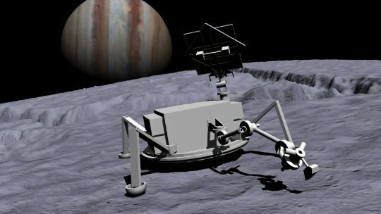
hrough advanced autonomy testbed programs, NASA is setting the groundwork for one of its top priorities—the search for signs of life and potentially habitable bodies in our solar system and beyond. The prime destinations for such exploration are bodies containing liquid water, such as Jupiter's moon Europa and Saturn's moon Enceladus.
Initial missions to the surfaces of these "ocean worlds" will be robotic and require a high degree of onboard autonomy due to long Earth-communication lags and blackouts, harsh surface environments, and limited battery life.
Technologies that can enable spacecraft autonomy generally fall under the umbrella of Artificial Intelligence (AI) and have been evolving rapidly in recent years. Many such technologies, including machine learning, causal reasoning, and generative AI, are being advanced at non-NASA institutions.
NASA started a program in 2018 to take advantage of these advancements to enable future icy world missions. It sponsored the development of the physical Ocean Worlds Lander Autonomy Testbed (OWLAT) at NASA's Jet Propulsion Laboratory in Southern California and the virtual Ocean Worlds Autonomy Testbed for Exploration, Research, and Simulation (OceanWATERS) at NASA's Ames Research Center in Silicon Valley, California.
NASA solicited applications for its Autonomous Robotics Research for Ocean Worlds (ARROW) program in 2020, and for the Concepts for Ocean worlds Life Detection Technology (COLDTech) program in 2021.
Six research teams, based at universities and companies throughout the United States, were chosen to develop and demonstrate autonomy solutions on OWLAT and OceanWATERS. These two- to three-year projects are now complete and have addressed a wide variety of autonomy challenges faced by potential ocean world surface missions.
OWLAT
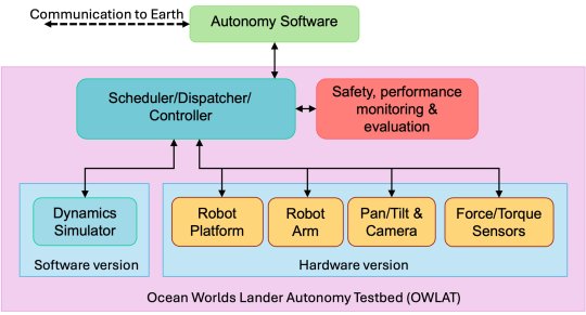
OWLAT is designed to simulate a spacecraft lander with a robotic arm for science operations on an ocean world body. Each of the OWLAT components is detailed below.
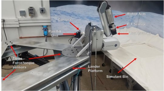
The hardware version of OWLAT is designed to physically simulate motions of a lander as operations are performed in a low-gravity environment using a six degrees-of-freedom (DOF) Stewart platform. A seven DOF robot arm is mounted on the lander to perform sampling and other science operations that interact with the environment. A camera mounted on a pan-and-tilt unit is used for perception.
The testbed also has a suite of onboard force/torque sensors to measure motion and reaction forces as the lander interacts with the environment. Control algorithms implemented on the testbed enable it to exhibit dynamics behavior as if it were a lightweight arm on a lander operating in different gravitational environments.
The team also developed a set of tools and instruments to enable the performance of science operations using the testbed. These various tools can be mounted to the end of the robot arm via a quick-connect-disconnect mechanism. The testbed workspace where sampling and other science operations are conducted incorporates an environment designed to represent the scene and surface simulant material potentially found on ocean worlds.
The software-only version of OWLAT models, visualizes, and provides telemetry from a high-fidelity dynamics simulator based on the Dynamics And Real-Time Simulation (DARTS) physics engine developed at JPL. It replicates the behavior of the physical testbed in response to commands and provides telemetry to the autonomy software.
The autonomy software module interacts with the testbed through a Robot Operating System (ROS)-based interface to issue commands and receive telemetry. This interface is defined to be identical to the OceanWATERS interface. Commands received from the autonomy module are processed through the dispatcher/scheduler/controller module and used to command either the physical hardware version of the testbed or the dynamics simulation (software version) of the testbed.
Sensor information from the operation of either the software-only or physical testbed is reported back to the autonomy module using a defined telemetry interface. A safety and performance monitoring and evaluation software module ensures that the testbed is kept within its operating bounds. Any commands causing out of bounds behavior and anomalies are reported as faults to the autonomy software module.
OceanWATERS
At the time of the OceanWATERS project's inception, Jupiter's moon Europa was planetary science's first choice in searching for life. Based on ROS, OceanWATERS is a software tool that provides a visual and physical simulation of a robotic lander on the surface of Europa.
OceanWATERS realistically simulates Europa's celestial sphere and sunlight, both direct and indirect. Because we don't yet have detailed information about the surface of Europa, users can select from terrain models with a variety of surface and material properties. One of these models is a digital replication of a portion of the Atacama Desert in Chile, an area considered a potential Earth-analog for some extraterrestrial surfaces.
JPL's Europa Lander Study of 2016, a guiding document for the development of OceanWATERS, describes a planetary lander whose purpose is collecting subsurface regolith/ice samples, analyzing them with onboard science instruments, and transmitting results of the analysis to Earth.
The simulated lander in OceanWATERS has an antenna mast that pans and tilts; attached to it are stereo cameras and spotlights. It has a 6 degree-of-freedom arm with two interchangeable end effectors—a grinder designed for digging trenches, and a scoop for collecting ground material. The lander is powered by a simulated non-rechargeable battery pack. Power consumption, the battery's state, and its remaining life are regularly predicted with the Generic Software Architecture for Prognostics (GSAP) tool.
To simulate degraded or broken subsystems, a variety of faults (e.g., a frozen arm joint or overheating battery) can be "injected" into the simulation by the user; some faults can also occur "naturally" as the simulation progresses, e.g., if components become over-stressed. All the operations and telemetry (data measurements) of the lander are accessible via an interface that external autonomy software modules can use to command the lander and understand its state. (OceanWATERS and OWLAT share a unified autonomy interface based on ROS.)
The OceanWATERS package includes one basic autonomy module, a facility for executing plans (autonomy specifications) written in the PLan EXecution Interchange Language, or PLEXIL. PLEXIL and GSAP are both open-source software packages developed at Ames and available on GitHub, as is OceanWATERS.
Mission operations that can be simulated by OceanWATERS include visually surveying the landing site, poking at the ground to determine its hardness, digging a trench, and scooping ground material that can be discarded or deposited in a sample collection bin. Communication with Earth, sample analysis, and other operations of a real lander mission, are not presently modeled in OceanWATERS except for their estimated power consumption.
Because of Earth's distance from the ocean worlds and the resulting communication lag, a planetary lander should be programmed with at least enough information to begin its mission. But there will be situation-specific challenges that will require onboard intelligence, such as deciding exactly where and how to collect samples, dealing with unexpected issues and hardware faults, and prioritizing operations based on remaining power.
Results
All six of the research teams used OceanWATERS to develop ocean world lander autonomy technology and three of those teams also used OWLAT. The products of these efforts were published in technical papers, and resulted in the development of software that may be used or adapted for actual ocean world lander missions in the future.
TOP IMAGE: Artist's concept image of a spacecraft lander with a robot arm on the surface of Europa. Credits: NASA/JPL – Caltech
CENTRE IMAGE The software and hardware components of the Ocean Worlds Lander Autonomy Testbed and the relationships between them. Credit: NASA/JPL – Caltech
LOWER IMAGE: The Ocean Worlds Lander Autonomy Testbed. A scoop is mounted to the end of the testbed robot arm. Credit: NASA/JPL – Caltech
BOTTOM IMAGE: Screenshot of OceanWATERS. Credit: NASA/JPL – Caltech
2 notes
·
View notes
Text
Digital Bottle Cap Torque Tester

Source of Info: https://www.perfectgroupindia.co.in/blog/digital-bottle-cap-torque-tester
Introduction
With the goal to guarantee unchanging sealing quality the Digital Bottle Cap Torque Tester is an accurate tool made to measure the torque needed to open or close bottle caps. Its digital displays and accurate real-time readings make it excellent for industries such as food, drinks, cosmetics and medicines. In the process of reducing leaks and maintaining customer safety this tester helps maintain package standards. It improves quality control procedures with features including collecting data, customizable settings and simple to use control. In order to provide effective and dependable package testing across the manufacturing processes Perfect Group India provides advanced designs that are customized for a range of cap sizes and types.
Why Torque Testing Matters Torque testing is a method of measuring the amount of rotational force needed to put on or take off a bottle cap. Excessive torque can harm the cap or seal and make opening the bottle challenging. Poor torque can lead to damage, leakage and weakened product quality. Every cap is sealed according to exact standards by a trustworthy Bottle Cap Torque Tester to maintain the delicate balance between safety and use. We at Perfect Group India understand the value of packaging quality. With its excellent packing performance we will help you stop product loss, conform with industry standards and improve consumer trust in your company.
Modern Technology Right at Your Fingertips The testers from Perfect Group India combine the latest digital technology to produce reliable and accurate readings. Our equipment offers unmatched accuracy and ease of use with features like digital torque displays, customizable settings and simple to use controls.
Our torque testers are equipped with:
High resolution sensors for precise measurements
Data logging capabilities to track and analyze torque trends
User calibration functions for continued measurement reliability
Compact and robust designs suitable for lab or production floor use
Applications Across Industries A Bottle Cap Torque Tester is useful in a variety of industries:
Pharmaceuticals: Make sure that child resistant caps work properly while keeping user comfort.
Beverage: It prevents leaks and spoiling caused by poor capping.
Cosmetics: Maintains a premium user experience through smooth cap removal.
Food & Dairy: Supports hygiene and freshness by maintaining optimal sealing.
Why Choose Perfect Group India? Perfect Group India is more than just a manufacturer but we are a packaging quality partner. This is what separates us in the Bottle Cap Torque Tester Industry:
Proven Track Record: With years of experience in accuracy testing equipment our products are trusted by top brands all over the world.
Customer Focused Design: Every tester is designed with the final user in mind. It's simple to use, easy to maintain and extremely useful.
After Sales Support: We provide complete training, testing maintenance and repair services to help you get the best out of your investment.
Made in India, Trusted Worldwide: Our solutions are designed and built locally while keeping up to globally quality standards.
Digital Versus Analog: The Future is Here While old analog testers have fulfilled their purpose, the future is definitely digital. A digital Bottle Cap Torque Tester has many benefits over its analog predecessor, including real time data recording, customizable testing modes and higher accuracy. The latest models from Perfect Group India include clear LCD panels, USB connectivity for data export and multitasking controls. This digital edge allows for easy connection with current manufacturing and quality control processes.
Sustainability and Quality Assurance Manufacturers can achieve more sustainable operations through the use of a Bottle Cap Torque Tester from Perfect Group India. Accurate torque adjustment saves cap waste, product recalls and overall material use which benefits both the environment and your bottom line. Also, quality assurance is simplified. Accurate torque readings allow your QA team to swiftly detect and solve faults guaranteeing excellent production quality.
Customization and Scalability To deal with different bottle sizes and cap types Perfect Group India provides a variety of models and torque levels. We have a Bottle Cap Torque Tester that has been created for you, no matter how big or little your business is. In order to make sure that you never have to sacrifice effectiveness or quality our technical team is also working closely with clients to provide innovative solutions for specific packaging problems.
Training and Calibration Services Your technical and Testing staff can receive training sessions from Perfect Group India to optimize the performance of your Bottle Cap Torque Tester. For a long time accuracy maintenance we also provide yearly testing and calibration services. Along with reducing the possibility of packing errors and improving quality operations, this guarantees that your staff remains safe and legal.
Conclusion Packaging requires accuracy and the best tool for doing it is the Bottle Cap Torque Tester from Perfect Group India. From based on industry customization to digital innovation we offer you a complete torque testing solution that offers accuracy, reliability and lasting value. If your top goals are customer pleasure, quality and security now is the time to make the best investment. For accurate packaging pick Perfect Group India as your reliable partner.
#industrial#equipments#perfectgroupindia#perfectinstruments#technology#droptester#business#boxcampressiontester
0 notes
Text
The Secret to Powerful Cleaning Robots? Smart Electronics Design
Table of Contents
Why Electronics Design Matters for Cleaning Robots
Core Electronics Components in Industrial Cleaning Robots 2.1 Microcontrollers and Processors 2.2 Motor Drivers and Controllers 2.3 Sensor Systems 2.4 Power Systems 2.5 Communication Modules
How Smart Electronics Enhance Cleaning Robot Performance 3.1 Autonomous Navigation 3.2 Adaptive Cleaning Modes 3.3 Self-Diagnostics and Maintenance Alerts 3.4 Ruggedness and Reliability
Real-World Example: Industrial Floor Cleaning Robots
Future Trends in Electronics for Cleaning Robots
Conclusion

The Secret Behind Powerful, Efficient Cleaning Robots? Advanced Electronics Design
The secret behind powerful, efficient cleaning robots lies in advanced electronics design — enabling precise control, durable operation, and intelligent automation. Whether it’s industrial cleaning robots scrubbing factory floors or autonomous vacuum bots in offices, smart electronics are the brains and nervous system that allow these machines to clean thoroughly, adapt to complex environments, and operate reliably over long hours.
If you want to understand how modern cleaning robots deliver outstanding performance and why electronics design is the key differentiator, keep reading. This article breaks down the essential role of electronics in powering industrial cleaning robots and how innovation is driving the future of automated cleaning.
Why Electronics Design Matters for Cleaning Robots
Cleaning robots operate in tough environments, often facing dirt, moisture, and heavy use. Their ability to navigate complex spaces, detect obstacles, and perform cleaning tasks autonomously depends largely on their electronic systems.
A well-engineered electronics design ensures:
Efficient motor control: For precise movement and cleaning action
Sensor integration: To map spaces, detect dirt, and avoid obstacles
Robust power management: For long battery life and safe operation
Durability: Protection against dust, water, and impacts
Without sophisticated electronics, cleaning robots wouldn’t be able to maintain the reliability or effectiveness expected in industrial environments.
Core Electronics Components in Industrial Cleaning Robots
1. Microcontrollers and Processors These act as the robot’s brain, running the software that controls everything from movement to cleaning cycles. Powerful microcontrollers enable real-time decision-making and sensor fusion.
2. Motor Drivers and Controllers Precise motor control is essential for navigating and adjusting cleaning patterns. Electronics regulate speed, torque, and direction of wheels and brushes, ensuring consistent cleaning quality.
3. Sensor Systems Cleaning robots rely on sensors such as:
LIDAR and ultrasonic sensors for distance measurement and obstacle detection
Optical sensors for dirt detection
Gyroscopes and accelerometers for navigation stability
Electronics design ensures seamless data flow from these sensors to the processor for real-time analysis.
4. Power Systems Battery management electronics monitor charge levels, optimize power usage, and protect against overcharging or overheating, which is crucial for safety and longer operational cycles.
5. Communication Modules Wireless connectivity modules (Wi-Fi, Bluetooth) enable remote monitoring, software updates, and integration with other smart systems.
How Smart Electronics Enhance Cleaning Robot Performance
Autonomous Navigation Advanced electronics enable cleaning robots to build detailed maps of their environment and plan efficient cleaning paths. Sensors provide real-time feedback, while the processor adjusts motion and cleaning functions dynamically.
Adaptive Cleaning Modes Robots can switch cleaning intensity based on detected floor types or dirt levels. Electronics control motors and brushes accordingly, optimizing battery life and cleaning results.
Self-Diagnostics and Maintenance Alerts Electronics monitor system health and notify operators about maintenance needs, preventing downtime and extending robot lifespan.
Ruggedness and Reliability Designing electronics with protective coatings and sealed enclosures ensures robots withstand industrial conditions like dust, moisture, and mechanical shocks.
Real-World Example: Industrial Floor Cleaning Robots
Consider an industrial floor cleaning robot deployed in a large warehouse:
It uses LIDAR sensors and a high-performance microcontroller to navigate aisles
Its electronics manage brush motors with variable speed depending on floor surface
Power electronics optimize battery use to cover large areas without recharge
The system sends performance data to a cloud dashboard via Wi-Fi, enabling real-time monitoring

Such capabilities are only possible through thoughtful electronics design tailored to the demands of industrial cleaning.
Future Trends in Electronics for Cleaning Robots
AI-Driven Cleaning Optimization Integrating AI with electronics allows robots to learn the most efficient cleaning paths and adapt schedules based on usage patterns.
Enhanced Sensor Fusion Combining data from multiple sensor types improves navigation accuracy and cleaning precision.
Modular Electronics for Easy Upgrades Future designs focus on modular PCBs and plug-and-play components to simplify repairs and upgrades.
Energy Harvesting Technologies Innovations in electronics may enable robots to recharge partially via kinetic or solar energy, increasing uptime.
Conclusion
The power and efficiency of cleaning robots — especially in demanding industrial settings — depend heavily on advanced electronics design. From controlling motors and processing sensor data to managing power and communication, smart electronics enable these robots to clean smarter, longer, and more reliably than ever before.
For companies seeking to automate cleaning processes and improve operational efficiency, investing in cutting-edge electronics design is the real secret to unlocking the full potential of industrial cleaning robots.
Every great cleaning robot starts with great electronics. If you’re planning your next product or upgrading an existing one, our design services are built to help you go further — faster. See how we can help
#CleaningRobots#ElectronicsDesign#RoboticsEngineering#SmartAutomation#EmbeddedSystems#IndustrialAutomation#RobotDesign#AutomationTechnology#AdvancedElectronics
0 notes
Text
How Does the Range Rover 3.0 Engine Support Adaptive Cruise Control in the HSE Model?

The Range Rover HSE is renowned for its luxury, innovation, and performance. Among its standout features is Adaptive Cruise Control (ACC), a system that automatically adjusts the vehicle’s speed to maintain a safe distance from the vehicle ahead. This function relies heavily on the seamless coordination between software, sensors, and the vehicle’s powertrain—especially the engine. The Range Rover 3.0 engine, known for its refinement and capability, plays a critical role in delivering the smooth and responsive behavior expected from adaptive systems in the HSE trim. Powered by an advanced 3.0-litre inline-six engine with mild hybrid support, the HSE delivers both power and control. We explores how the Range Rover engine supports Adaptive Cruise Control operations and how reconditioned engines also offer the same reliability and integration when properly restored. We’ll break down the interaction between the engine and ACC systems, emphasizing precision, safety, and efficiency.
Understanding Adaptive Cruise Control in the HSE Model
Adaptive Cruise Control (ACC) in the Range Rover HSE is designed to automatically maintain a safe distance from vehicles ahead. Unlike conventional cruise control systems that only maintain a set speed, ACC dynamically adjusts throttle input and braking. This is especially beneficial during long highway drives or in slow-moving traffic. The system relies on radar sensors, cameras, and engine integration to measure distances and detect changes in traffic flow. The Range Rover 3.0 engines is central to this process. When ACC commands acceleration or deceleration, the engine responds almost instantly to ensure smooth and safe adjustments. The system must rely on the engine’s responsiveness and precise torque delivery for these transitions to be seamless. Even when using reconditioned engines, the ACC system can function optimally—provided the engine has been rebuilt to OEM standards. The engine must support all necessary communication protocols and sensor integrations to maintain the fluid control required for ACC operation in the HSE model.
The Role of the 3.0 Engine's Mild Hybrid System in Smooth Acceleration
One of the key attributes of the Range Rover 3.0 engine is its mild hybrid electric vehicle (MHEV) system. This system enhances the engine’s responsiveness by utilizing a 48V electric motor that assists during acceleration. In Adaptive Cruise Control scenarios, this electric support smooths out any lag between the ACC system's commands and the engine’s actual performance. When the ACC system demands a speed increase to keep pace with traffic, the mild hybrid system adds instant torque, allowing the engine to respond quickly without jerks or sudden surges. This makes the ride feel more refined and helps maintain passenger comfort. Reconditioned engines that include properly rebuilt or replaced MHEV components can replicate the same level of smoothness. High-quality reconditioning ensures that the electric assist and regenerative braking systems work in harmony with the ACC module, keeping the performance consistent and luxurious.
Engine Braking and Deceleration Support During Cruise Control
Engine braking is a natural way to reduce speed without relying entirely on the vehicle’s braking system. In Adaptive Cruise Control mode, the Range Rover 3.0 engine contributes to deceleration by reducing fuel injection and allowing internal friction to slow the vehicle. This technique provides more control and preserves brake life. When descending slopes or approaching a slower vehicle, ACC intelligently uses engine braking along with actual brakes to moderate the car’s speed. The system must communicate effectively with the engine to execute these smooth transitions. For reconditioned engines, this ability is preserved when the ECU is correctly programmed and compatible with ACC features. Even a rebuilt Range Rover engine, when restored with precision, will support the same level of integrated deceleration and braking, making it suitable for high-tech driver assist systems.
Adaptive Throttle Control for Changing Traffic Conditions
In urban or congested traffic, Adaptive Cruise Control faces a different challenge: frequent start-stop movement. The Range Rover 3.0 engine meets this challenge through its finely tuned throttle control, which allows micro-adjustments to power delivery. The inline-six design, combined with turbocharging and hybrid assistance, ensures that the engine can ramp power up or down smoothly and accurately. These adjustments are especially noticeable during stop-and-go traffic, where ACC must restart the vehicle and maintain low speeds while adjusting spacing. Reconditioned engines that include restored throttle bodies, recalibrated ECUs, and hybrid components maintain this precision. So long as the rebuilding process follows factory-grade procedures, reconditioned Range Rover engines remain fully capable of providing the adaptive throttle modulation needed for modern cruise control features.
Integration with Forward Collision Detection and Safety Systems
The ACC system in the Range Rover HSE is linked with forward collision detection, which uses sensors and predictive algorithms to identify potential collisions. If a threat is detected, the engine management system quickly reduces throttle input or cuts power entirely to help avoid or minimize impact. The 3.0 engine’s electronic management system must work in real time with these sensors. Its rapid response rate and ability to quickly alter torque output play a crucial role in ensuring the vehicle reacts instantly to danger. The smooth integration between the ACC and the engine enhances overall safety and confidence on the road. Reconditioned engines, when fitted with updated software and tested ECU configurations, can function seamlessly with these safety systems. These engines are thoroughly inspected to ensure that all electronic connections and responses are in line with safety standards.
Enhancing Fuel Efficiency Through Intelligent Cruise Modulation
One of the understated benefits of Adaptive Cruise Control is its ability to optimize fuel consumption. The Range Rover 3.0 engine, with its mild hybrid support, contributes significantly to this by reducing unnecessary acceleration and deceleration events. By maintaining consistent engine loads and using regenerative braking, the system ensures fuel-efficient cruising. This efficiency is amplified during long highway journeys where minor throttle changes can lead to significant fuel savings. The mild hybrid system further assists by powering auxiliary components and allowing smoother stop-start functionality. Reconditioned engines with properly functioning hybrid modules and efficient combustion characteristics can match these fuel-saving features. When rebuilt correctly, they maintain tight tolerances and electronic calibration, ensuring minimal fuel consumption while supporting ACC functionality.
Communication Between the Engine ECU and Cruise Control Modules
Behind the scenes, complex data exchange occurs between the engine control unit (ECU) and the adaptive cruise control module. The Range Rover 3.0 engine’s ECU processes throttle inputs, brake pressure, torque requests, and regenerative braking status in real time. ACC relies on this live data to make informed decisions about vehicle speed and spacing. The ECU must not only interpret these signals quickly but also execute changes to engine performance instantaneously. The effectiveness of ACC is directly tied to how well the engine ECU responds to this continuous stream of data. For reconditioned engines, ECU compatibility and calibration are key. During engine restoration, specialists ensure that the ECU supports the required protocols and software versions needed to interact with modern driver-assist systems. When this is done correctly, reconditioned engines offer the same reliability and responsiveness as new units.
Maintaining Comfort and Refinement in Cruise Conditions
Luxury vehicles like the Range Rover HSE are expected to deliver not just functionality but also refinement. The 3.0 engine contributes to this by offering near-silent operation, smooth power transitions, and vibration-free performance. When ACC is active, any roughness or delay in power delivery can negatively impact the driving experience. The six-cylinder configuration, along with advanced engine mounts and noise-reducing components, ensures that the engine runs smoothly even during frequent adjustments by the cruise control system. The mild hybrid’s electric motor also reduces engine strain at low speeds, enhancing comfort. A properly reconditioned Range Rover engine can replicate this experience. Noise-dampening materials, engine balancing, and professional tuning during reconditioning ensure that luxury and comfort are preserved. This means even with a reconditioned engine, the HSE model maintains its hallmark smoothness. Read the full article
#RangeRover3.0Engine#RangeRover3.0EngineForSale#RangeRover3.0Engines#RangeRover3.0EnginesforSale#ReconditionedRangeRover3.0Engines#ReconditionedRangeRover3.0Enginesforsale
0 notes
Text
Why a Torque Sensor eBike Feels Better Than You’d Expect
It's Not Just Power, It's a Partnership
Forget the feeling of a motor simply pushing you along. A torque sensor ebike offers something far more advanced: a true partnership between you and your bike. It feels less like a machine and more like a supercharged version of your own body. This natural connection is the magic of a high-quality ebike torque sensor.
The Feel of Amplified Ability
It doesn't just give you power; it smartly amplifies your effort. This creates a ride that feels responsive and surprisingly natural.
Listening to Your Legs
The core of this premium experience lies in how the bike "listens" to you. Unlike basic cadence sensors that act like an on/off switch (they only know if you're pedaling), a torque sensor measures how hard you're pedaling. Understanding the different types of e-bike motors and their sensors is key to finding the right ride. Think of it this way: a cadence sensor is a light switch, while a torque sensor is a dimmer switch, giving you smooth control.

How a Sensor Transforms Your Ride
An ebike torque sensor acts almost like a sixth sense, knowing the power you need before you even ask for it. A modern torque sensor can take hundreds of measurements per pedal stroke, ensuring instant and precise power delivery. This is a core aspect of how e-bike motors work in harmony with the rider. This translates into real benefits:
Intuitive Control: The bike gives you exactly what you ask for. Push harder for more power, ease off for less. This is crucial for navigating tight spots or busy streets.
Seamless Acceleration: No more jerky starts. The power delivery is smooth from the first push, making starting on a hill effortless and safe.
Enhanced Battery Efficiency: The motor only provides the power you need, not wasting energy on full blast when you're soft-pedaling. This often extends your range.
A Real Workout, Your Way: You get a great workout because you are always contributing. The bike assists, it doesn't take over, offering superior control over your fitness.
Real-World Scenarios
This technology truly shines in common riding situations where you'll feel the difference firsthand.
Where You'll Truly Feel It
Tackling a Steep Hill: As the incline gets steeper, your legs naturally push harder. The torque sensor instantly matches your effort with proportional power, making you feel strong and capable, not like the motor is just taking over at a single, awkward speed.
Starting from a Dead Stop: At an intersection, a gentle push on the pedal results in immediate, smooth forward motion. There's no lurch or delay, giving you confidence and control when you need it most.
Navigating Slow Traffic: Weaving through a busy area becomes second nature. Tiny adjustments in pedal pressure give you precise speed changes, making you feel far safer and more connected to the bike than with a clunky cadence system.
The Smart Rider's Choice
Ultimately, choosing an e-bike sensor is about what you value in a ride. A cadence sensor offers a simple motorized boost. But for a ride that feels natural, responsive, and truly connected—like an extension of your own will—the ebike torque sensor is the clear choice for the smart rider.
FAQ
Q: What is the main difference between a Cadence vs Torque Sensor?
A: A torque sensor measures how hard you pedal, while a cadence sensor only detects if you're pedaling. This means torque sensors provide smooth, proportional power that matches your effort, while cadence sensors give fixed power levels like an on/off switch.
Q: Do torque sensor ebikes provide better battery life?
A: Yes, torque sensor ebikes typically offer better battery efficiency. The motor only provides the exact amount of power you need based on your pedaling effort, rather than delivering full power whenever you pedal like cadence sensors do.
Q: Are torque sensor ebikes harder to ride?
A: No, torque sensor ebikes are actually easier and more intuitive to ride. They feel more natural because the motor assistance matches your pedaling effort, creating a seamless riding experience that feels like an enhanced version of regular cycling.
Q: Can I still get exercise on a torque sensor ebike?
A: Absolutely! Torque sensor ebikes encourage more exercise because you're always contributing to the pedaling. The motor amplifies your effort rather than replacing it, so you can control how much workout you want while still getting assistance when needed.
Q: Are torque sensor ebikes worth the extra cost?
A: For most riders, yes. The natural feel, better battery efficiency, smoother acceleration, and precise control make torque sensor ebikes a worthwhile investment, especially if you plan to ride regularly or tackle varied terrain like hills and city streets.
0 notes
Text
Pacorr Bottle Cap Torque Tester – Accurate Torque Measurement for Perfect Packaging
Pacorr brings precision and reliability to your packaging lines with its advanced Bottle Cap Torque Tester. In industries where safety, freshness, and user convenience matter most, the integrity of bottle closures plays a key role. Loose caps can lead to leakage or contamination, while overly tight caps may result in consumer complaints or breakage.

To avoid such issues and ensure compliance with packaging standards, Pacorr’s torque tester helps manufacturers measure the exact amount of torque applied to bottle caps during sealing and unsealing operations. This instrument is a vital part of quality control in industries like pharmaceuticals, food and beverages, cosmetics, and personal care.
Benefits of Using a Bottle Cap Torque Tester
Ensures packaging consistency across batches
Improves customer satisfaction with optimal sealing
Prevents product wastage due to leakage or breakage
Supports regulatory compliance with international standards
Reduces the risk of recalls and product failures
With the Pacorr Bottle Cap Torque Testing, brands can maintain the balance between secure sealing and consumer convenience.
Key Features of Pacorr’s Torque Tester
Accurate Digital Display Equipped with high-precision sensors, the tester offers reliable readings for both opening and closing torque.
Universal Grip Fixture The fixture can be adjusted to accommodate bottles of various shapes and sizes, making it versatile for multiple product types.
User-Friendly Operation Simple controls allow operators to conduct tests easily and view torque results instantly.
Dual Testing Mode The instrument supports testing for both removal torque (when the cap is opened) and application torque (when the cap is sealed).
Data Output Options Some models allow data logging and export via USB or RS232, supporting batch traceability and audit requirements.
Robust Construction Built for industrial use, the tester is durable and stable, offering consistent performance even under rigorous testing conditions.
Applications Across Industries
Pharmaceutical Industry Maintains sealing integrity of liquid medicines and ensures safety of child-resistant caps.
Food and Beverage Sector Prevents leakage and maintains freshness in juices, sauces, carbonated drinks, and edible oils.
Cosmetic and Personal Care Assures leak-free packaging in lotions, creams, and serums where shelf appeal and hygiene matter.
Chemical and Industrial Packaging Validates closure strength of chemical containers to avoid hazardous spills.
How to Use the Bottle Cap Torque Tester
Place the sample bottle in the adjustable grip fixture.
Tighten the cap manually or use the automated capping system.
Initiate the test using the interface and choose between open or close torque measurement.
Observe the results displayed on the screen.
Record or export data as required for quality documentation.
This simple testing process ensures that every batch meets required standards before packaging moves forward.
Technical Overview
Torque Range: 0.1 to 10 Nm (customizable as per need)
Display: Digital / Touchscreen
Accuracy: ±0.5 percent of full scale
Resolution: 0.01 Nm
Grip Type: Adjustable universal clamp
Output: USB / RS232 (optional)
Power Supply: 220V AC, 50 Hz
Why Choose Pacorr?
Pacorr Testing Instruments is trusted by quality professionals across industries for its reliable and cost-effective testing equipment. Our Bottle Cap Torque Tester Price is built using industry-leading components, calibrated to high standards, and supported by a knowledgeable technical team.
From lab-scale testing to full-scale production lines, Pacorr’s solutions are built to support your quality assurance goals while enhancing operational efficiency.
Common Questions (FAQs)
What is a torque tester used for? It measures the rotational force required to open or close a bottle cap to ensure proper sealing.
Which caps can be tested? The tester is compatible with plastic, metal, and child-resistant screw-type caps.
Is this suitable for all bottle sizes? Yes, the adjustable clamp fits bottles of various diameters and shapes.
Does it meet international standards? Yes, it follows standards such as ASTM D2063 and ISO 8113 for cap torque testing.
Can data be exported for reports? Digital models allow easy data export via USB or RS232 for quality audits.
Conclusion
The Bottle Cap Torque Tester by Pacorr is a critical tool for manufacturers aiming to deliver secure, leak-proof packaging. With its high accuracy, user-friendly interface, and flexible testing capabilities, it ensures every product reaches the customer with optimal quality.
For industries where sealing strength directly affects safety, freshness, and satisfaction, Pacorr provides the torque testing reliability you need.
Upgrade your packaging quality control today—choose Pacorr’s Bottle Cap Torque Tester.
0 notes
Text
How Do Expert Mechanics Diagnose and Deliver Lasting Repairs

In the world of automotive care, not all repairs are created equal. Some fixes are rushed patches that barely get you to your next stop. Others are the result of thoughtful diagnostics and skilled hands, ensuring your car runs smoothly for miles to come. It all comes down to the difference a professional makes—specifically, an expert mechanic who knows exactly how to combine precision, experience, and modern tools for long-term results. That's the real value of reliable car mechanic repair.
The Art of Automotive Diagnosis
True experts don't just "look around" and guess. They start with a methodical diagnostic approach. From the moment a car rolls into the bay, the mechanic becomes a detective, gathering clues to pinpoint the root of the problem.
Listening to the Driver: First, they ask you what you've noticed—noises, smells, performance dips. Your observations are valuable data.
Initial Inspection: They check visible components, fluid levels, and warning indicators.
Diagnostic Tools: Using scan tools, they read trouble codes from your car's onboard computer. These codes don't give all the answers—but they point to where to look.
This multi-layered approach ensures mechanics avoid the trap of replacing parts that don't need fixing. That's what makes expert car mechanic repair both efficient and economical.
Experience That Speaks Volumes
What separates expert mechanics from the average ones? Experience. Years under the hood teach professionals to identify symptoms that don't show up in a diagnostic code.
That faint clicking when you turn? It could be a CV joint.
The smell of burnt oil? It might be a valve cover gasket.
Uneven tyre wear? It's likely a suspension or alignment issue.
These insights come from hundreds of similar cases, pattern recognition, and gut instinct refined over time. With experience, mechanics don't just solve issues—they anticipate them.
Tools That Talk to the Car
Modern vehicles are complex machines packed with sensors, modules, and advanced software. Today's mechanics are tech-savvy professionals who use:
OBD-II Scanners for engine and transmission codes
Multimeters to test electrical continuity
Oscilloscopes to measure voltage and waveform data
Thermal Cameras to spot overheating components
Torque Apps and digital specs to ensure every bolt is tightened perfectly
These tools don't replace the human brain—but they enhance a mechanic's ability to be thorough and accurate. Together, they ensure your car mechanic repair isn't just a band-aid—it's a solid fix.
The Process of Delivering a Lasting Repair
Once the diagnosis is complete, the real magic begins. Lasting repairs follow a process that prioritizes reliability and performance:
Root-Cause Correction: Mechanics focus on fixing the actual cause—not just the symptom. If a misfire is due to a faulty coil pack and not just a worn spark plug, both issues are addressed.
OEM or Quality Aftermarket Parts: Professionals don't cut corners. They use trusted parts that match or exceed the original quality.
Clean Installation: Every part is installed with precision. No guesswork. No shortcuts.
Testing and Verification: After the repair, mechanics test your vehicle again—road tests, scan tool checks, and sometimes follow-ups.
It's this commitment to doing the job right, not just fast, that sets expert repairs apart.
Preventative Advice You Can Trust
A great mechanic doesn't just repair—they educate. Once your vehicle is back in working order, they offer maintenance suggestions based on what they've seen:
"Your brake pads have 30% life left—consider replacing them soon."
"Coolant was a little low; check for a slow leak."
"Your tyres are showing feathering—alignment might be due."
These tips help you avoid future breakdowns and extend the life of your car. It's the proactive mindset behind quality car mechanic repair that saves you time and money in the long run.
Customer-Centered Service Makes It Even Better
What makes the repair process even more satisfying is the transparency and respect shown. Expert mechanics understand that most people aren't car experts, so they explain things clearly:
They walk you through what's wrong.
They provide honest estimates and options.
They let you know what's urgent and what can wait.
This honest, people-first approach builds trust—and that trust keeps drivers coming back.
Long-Term Benefits of Expert Repairs
Still, wondering why it matters who fixes your car? Here's what expert-level car mechanic repair gives you over time:
Fewer breakdowns and emergency calls
Increased vehicle lifespan and resale value
Improved fuel economy
More confidence behind the wheel
Lower total maintenance costs over the years
In short, quality work pays off—both financially and emotionally. You spend less time worrying about your car and more time enjoying the drive.
Final Thoughts: Not Just a Fix—A Partnership
An expert mechanic isn't just someone you visit when things go wrong. They become a long-term partner in your car's health. Their insights, advice, and skilled repairs keep you moving forward, no matter the miles.
So next time your engine stutters, your brakes squeal, or that check engine light blinks on, remember this: you don't just need a fix. You need the expertise, care, and commitment that only a seasoned professional can provide.
That's the difference between a quick repair and a lasting solution—and why expert car mechanic repair is one of the smartest investments you'll ever make.
0 notes
Text
Torque Sensors: Precision Force Monitoring Powered by Star EMBSYS Technology
Torque sensors are essential tools in the measurement and control of rotational force in mechanical systems. From automotive testing and industrial automation to aerospace and robotics, torque sensors enable engineers to monitor performance, ensure safety, and improve efficiency. Star EMBSYS, a leader in embedded system innovation, offers advanced torque sensor solutions that combine mechanical precision with intelligent electronics for high-performance applications.
A torque sensor, also known as a torque transducer, measures the torque—or rotational force—applied to a shaft or axis. It can be used in both static (non-rotating) and dynamic (rotating) applications, making it highly versatile. Depending on the requirement, torque sensors can be based on strain gauge, magnetoelastic, or optical technologies. The electrical signal generated is proportional to the torque applied, which is then processed for display, control, or data logging.
Star EMBSYS leverages its deep expertise in embedded systems to develop smart torque sensor solutions that provide real-time, high-resolution measurements. Their sensors are integrated with embedded microcontrollers for advanced signal conditioning, filtering, and digital communication. This results in more stable, noise-free data and allows for seamless integration into modern control systems.
What sets Star EMBSYS apart is their ability to offer custom torque sensor systems tailored to specific industrial needs. Whether for a precision laboratory setup or a rugged field environment, Star EMBSYS provides sensors that include temperature compensation, overload protection, and customizable output ranges. The embedded software also supports features like zero-torque calibration, peak-hold modes, and fault diagnostics.
For industries working with rotating machinery—such as electric motors, pumps, or wind turbines—Star EMBSYS torque sensors offer both static and rotary variants. These sensors can output analog signals (0–5V, 4–20mA) or digital data via UART, CAN, or SPI, providing flexibility for integration with PLCs, DAQs, or cloud-connected IoT platforms.
Moreover, Star EMBSYS includes support for wireless telemetry in demanding applications, allowing real-time torque data transmission without slip rings or complex wiring—ideal for mobile machinery or test benches.
In summary, torque sensors play a vital role in the monitoring and control of mechanical systems. With its focus on smart design, embedded innovation, and application-specific customization, Star EMBSYS delivers high-performance torque sensor solutions that empower engineers and manufacturers to measure with confidence, accuracy, and efficiency.
Visit:- https://www.starembsys.com/torque-sensor.html
0 notes
Text
What Role Does the ECU Play in Managing a Range Rover Engine?

The Engine Control Unit (ECU) is the brain of any modern vehicle, and in the case of the Range Rover engine, its role is even more critical. From monitoring performance to managing fuel efficiency and emissions, the ECU is responsible for controlling the essential systems that keep the engine running optimally. Whether you're driving a new model or considering reconditioned engines for your Range Rover, understanding how the ECU functions can help you appreciate the technology behind its superior performance. We’ll explore how the ECU manages various aspects of the Range Rover engine and why it’s central to engine performance, diagnostics, and reliability. What Is an ECU and Why Is It Crucial for a Range Rover Engine? The Engine Control Unit, or ECU, is an embedded computer system designed to manage and regulate engine functions. In a Range Rover engine, the ECU collects data from various sensors throughout the vehicle to make real-time decisions that optimize engine performance. These sensors measure variables such as air intake, engine temperature, throttle position, and exhaust gases. The ECU processes this information to adjust fuel injection, ignition timing, turbocharging, and even idle speed. This level of control ensures that the engine operates within safe and efficient parameters, reducing wear and improving fuel economy. In reconditioned engines, the ECU must be correctly programmed or recalibrated to match the engine specifications, ensuring peak performance after refurbishment. With today’s environmental regulations and performance demands, an advanced ECU is not just helpful—it’s essential. The ECU enables the Range Rover engine to meet emission standards while still delivering the power and torque that drivers expect from a luxury SUV. How the ECU Controls Fuel Injection in the Range Rover Engine Fuel injection is a core aspect of any internal combustion engine, and in the Range Rover, it's optimized through the ECU. Instead of relying on mechanical systems, the ECU uses input from oxygen sensors, mass airflow meters, and engine speed data to determine the exact amount of fuel needed for combustion. For example, during acceleration, the ECU increases fuel injection for more power, while during cruising, it adjusts for efficiency. This results in smoother performance, fewer emissions, and better fuel economy. This function is vital in both new and reconditioned engines, ensuring they meet performance benchmarks consistently. The Range Rover engines benefits from multi-point or direct fuel injection systems managed entirely by the ECU. Any malfunction in the ECU can lead to poor fuel economy, rough idling, or even engine misfires. That’s why ECU diagnostics are a standard part of Range Rover servicing, especially after an engine replacement or rebuild. Role of the ECU in Emission Control and Compliance Modern engines must comply with strict emissions regulations, and the ECU plays a pivotal role in achieving this. The Range Rover engine uses the ECU to manage the air-fuel ratio, exhaust gas recirculation (EGR), and catalytic converter performance. Sensors like the lambda (oxygen) sensor feed data back to the ECU, which adjusts the mixture to minimize harmful emissions such as nitrogen oxides (NOx) and hydrocarbons. The ECU also triggers onboard diagnostic trouble codes if it detects emission-related issues, such as inefficient catalytic converter operation or fuel vapor leaks. This role is even more important in reconditioned engines, where components are refurbished but need recalibration to meet emission standards. A properly functioning ECU ensures that a reconditioned Range Rover engine doesn't just run, but runs clean. In regions with stringent MOT or emissions testing, the ECU's role becomes critical. A malfunctioning ECU can result in failed tests and legal issues, underscoring its importance in engine management. ECU and Turbocharger Synchronization in Range Rover Engines Many Range Rover engines come equipped with turbochargers for enhanced power and efficiency. The ECU is responsible for managing turbo boost pressure and ensuring the system operates within safe limits. It controls wastegate actuation and monitors boost levels to prevent overboosting, which can damage the engine. Additionally, the ECU adjusts fuel and air ratios depending on turbo output, making sure the engine doesn't run lean or rich under boosted conditions. In reconditioned engines, especially those with rebuilt or replaced turbochargers, recalibrating the ECU is vital. A mismatch between the turbo's performance curve and ECU expectations can lead to poor performance or component failure. Thanks to ECU management, turbocharged Range Rover engines deliver seamless acceleration, superior towing capability, and efficient highway cruising—all without compromising reliability or emissions. Diagnosing Engine Faults with ECU Error Codes One of the most practical functions of the ECU is fault detection and reporting through On-Board Diagnostics (OBD). The ECU constantly checks for abnormalities in sensors, actuators, and other engine components. When something goes wrong—be it a misfire, faulty sensor, or fuel issue—the ECU logs an error code (DTC) that mechanics can read using diagnostic tools. These codes are invaluable in pinpointing issues quickly and accurately, reducing both labor time and repair costs. In the case of reconditioned engines, error codes can help identify if any component hasn’t been installed or configured correctly. It’s also helpful for post-installation health checks to ensure the refurbished engine is performing as expected. With advanced ECU systems in newer Range Rover models, diagnostics can even be monitored remotely, offering real-time data to service centers and giving owners peace of mind. ECU's Role in Adaptive Driving Modes and Terrain Response One of the standout features of the Range Rover engine is its ability to adapt to various driving conditions through Terrain Response. Whether you're off-roading, driving through snow, or cruising on the highway, the ECU adjusts engine performance, throttle response, and gear shifts accordingly.The ECU takes input from sensors that monitor wheel slip, steering angle, gradient, and speed, then makes rapid adjustments to deliver optimal traction and performance. These changes include modifying torque distribution, throttle sensitivity, and even suspension settings. This dynamic management system is impossible without the ECU acting as the coordinator. For reconditioned engines, the ECU must be reprogrammed to ensure it works seamlessly with all vehicle systems, including adaptive drive modes.The integration of the ECU in these advanced systems enhances safety, comfort, and efficiency, making the Range Rover a true all-terrain luxury SUV. ECU and Engine Protection: Preventing Damage and Overheating Beyond performance, the ECU also serves as a protective mechanism for the Range Rover engine. It monitors coolant temperature, oil pressure, and engine load, initiating safety protocols when necessary.If the engine overheats or the oil pressure drops below safe limits, the ECU can reduce power output or trigger limp mode to prevent severe damage. These preemptive actions often save drivers from catastrophic engine failure. For reconditioned engines, this is especially important as any reused components must work within manufacturer-specified tolerances. If the ECU detects inconsistencies, it logs a fault and adjusts operations accordingly. This proactive engine management system gives owners confidence, knowing their vehicle is equipped with smart protection against mechanical failure. Reprogramming and Updating the ECU in Reconditioned Engines When installing a reconditioned engine into a Range Rover, one of the most important steps is updating or reprogramming the ECU. Since each engine has unique calibration requirements—based on sensors, injectors, and turbo settings—the ECU must be synced to the new configuration. Specialist garages use OEM-grade diagnostic tools to upload new maps or software to the ECU, ensuring it matches the reconditioned engine's parameters. Failing to do this can lead to reduced performance, higher emissions, or even check engine lights. In some cases, especially with engine swaps or major overhauls, the ECU may need to be replaced entirely. A mismatched or outdated ECU can cause compatibility issues with other vehicle systems like the gearbox, fuel pump, or infotainment system. Accurate ECU programming ensures that a reconditioned engine performs just like a new one—delivering power, efficiency, and reliability seamlessly. Read the full article
0 notes
Text
Technical characteristics and maintenance measures of stepper motor drivers
1.Basic definition of stepper motor drivers A stepper motor driver is a device that converts an electrical pulse signal into a drive current signal, which is mainly used to control the angular displacement, speed and position of a stepper motor. The stepper motor driver receives the pulse signal from the controller and converts it into a drive current signal to control the operation of the stepper motor. The speed of the stepper motor is proportional to the pulse frequency, so the speed can be accurately adjusted by controlling the pulse frequency, and the positioning can be accurately achieved by controlling the number of pulses.

2.Working principle of stepper motor driver The main components of the stepper driver include a ring distributor and a power amplifier. The ring distributor is responsible for receiving pulse signals, direction signals and offline signals, and distributing and processing these signals. The power amplifier provides power to the coil of the stepper motor according to the instructions of the ring distributor, thereby controlling the operation of the motor. The stepper motor requires continuous pulse signal input to operate, otherwise it will stop rotating.
3.Technical features of stepper motor drivers
1.High-precision control: The stepper motor driver receives electrical pulse signals and accurately drives the stepper motor to rotate a fixed angle (i.e., the "step angle"), thereby achieving high-precision position control. Each pulse signal corresponds to a specific angle of motor rotation, which enables the stepper motor to achieve high-precision open-loop position control without a feedback system. 2. Advantages of open-loop operation: Stepper motor drivers have significant advantages under open-loop operation. Due to the "step-one-step-stop" characteristics of stepper motors, the driver can operate reliably without position sensor feedback by accurately controlling the pulse signal. This open-loop operation simplifies the system structure and reduces costs. 3. Controllable speed and direction: The stepper motor driver receives pulse signals and direction signals to control the motor's speed, number of steps, and direction of rotation, respectively. The higher the pulse frequency, the faster the motor speed; the direction signal determines whether the motor rotates clockwise or counterclockwise. 4. Low speed and high torque: The stepper motor can provide a large output torque at low speed, which makes it perform well in applications that require low speed and high torque. The driver maintains this advantage by ensuring that the motor coils receive sufficient and accurate current.
5.Programmable current control: Most stepper motor drivers allow users to set the peak current and operating current delivered to the motor, which directly affects the torque and heat output of the motor. Some drivers also support setting the holding current to reduce the heat generated when the motor stops.
6.Microstep drive technology: Modern stepper motor drivers usually provide microstep drive technology, which can achieve finer position control through subdivision control without changing the physical step angle of the motor, further improving the accuracy and performance of the system.

4.Maintenance measures for stepper motor drivers
1.Regular cleaning: Depending on the use environment, regularly clean the surface and interior of the stepper driver to remove dust and impurities. You can use clean gas to blow dust or a soft dry cloth to wipe it gently, but be careful not to use chemical solvents or strong acid and alkali solutions to avoid damage to the driver.
2.Check the connection: Regularly check whether the connection between the stepper driver and the stepper motor and control system is firm to ensure that there is no looseness. If looseness is found, it should be re-fixed in time. 3. Power supply check: Ensure that the power supply of the stepper driver is stable and the voltage meets the equipment standards. If the power supply is found to be unstable or abnormal, the fault should be promptly eliminated or the power supply equipment should be replaced. 4. Temperature control: Pay attention to the operating temperature of the stepper driver and avoid long-term high-temperature operation. You can add heat dissipation equipment such as fans or heat sinks to maintain the normal operating temperature of the driver. 5. Environmental protection: Install the stepper driver in a dry and well-ventilated environment to avoid moisture, excessive dust and other conditions that may adversely affect the equipment. When working in harsh environments, you can consider using dustproof, waterproof covers or shells to improve the protection level of the equipment. 6. Fault handling: If the stepper driver is abnormal or fails, first perform fault diagnosis according to the equipment manual, and repair or replace parts according to the methods provided in the manual. If the problem cannot be solved, you need to contact professional technicians for inspection.
0 notes
Text
Innovations in Press Machines: How New-Age Technologies Are Shaping Manufacturing
In the last decade, industrial presses have undergone steady but meaningful upgrades. The change isn’t loud—but it’s deep. From manual controls to fully programmable operations, today’s press machines are built for accuracy, consistency, and operational efficiency.
At SMT Parkash Presses, we’ve observed how the role of a press machine is no longer limited to just applying force. It’s about applying the right force, in the right direction, with minimal error and maximum repeatability.
Moving Beyond Basic Mechanics
Traditional presses were dependable, but limited. Today, the expectations are different. Manufacturers now ask for speed, precision, safety, and energy savings—all from one unit.
To meet that, modern presses now come with:
Programmable logic controllers (PLCs) for consistent, repeatable operations
Pressure sensors with load monitoring for real-time feedback
Stroke and speed adjustments for varied materials and component sizes
This level of control helps reduce part rejection and ensures uniform output, batch after batch.
Integration of Automation
One of the most practical changes in recent years is automation. Press machines, especially in high-volume plants, are increasingly being integrated with robotic systems. This allows for automatic feeding, positioning, and removal of parts.
It reduces dependency on manual labor, lowers the margin for error, and improves workplace safety. In industries like automotive or appliance manufacturing, this integration is now considered standard, not optional.
Energy Efficiency and Power Optimization
Our Press machines are high-power equipment. So, reducing energy consumption without affecting performance is a major area of innovation.
Technologies like servo-driven systems and variable frequency drives (VFDs) help adjust motor speed and torque as needed, rather than running at constant high power. Some systems even recover energy during return strokes or idle cycles, reducing overall consumption.
This matters not just from a cost angle—but also in terms of plant efficiency and load balancing.
Material Adaptability and Tooling Flexibility
Pressing needs have changed. It’s not just about mild steel or aluminum anymore. Composite materials, multi-metal layers, and high-strength alloys require machines that can adapt.
Newer presses are designed with modular tooling platforms and quick-change die systems. These allow for faster shift between product types and make low-volume, high-variation manufacturing viable.
This is particularly useful in setups handling custom jobs or frequent design changes.
Real Use Cases: Where New-Age Presses Fit
Across industries, presses with advanced features are making a measurable difference:
In automotive units, deep-draw presses with servo systems are being used for critical body parts
In electrical and electronics, small presses are used for circuit housing and casing, where precision matters
In appliance manufacturing, high-tonnage presses form panels with surface consistency and dimensional control
In sheet metal units, hydraulic presses are used for forming, trimming, and blanking—often in a single cycle
What This Means for Manufacturers
Today, investing in a press machine is no longer just about capacity—it’s about compatibility with current and future workflows. Machines that reduce downtime, adapt to multiple use cases, and offer precision are not an add-on—they’re a requirement.
Manufacturers, especially those working on tight timelines and tolerances, now expect machines that offer control, not just power.
Press Machine Manufacturers in India- SMT Parkash Presses is India's Leading Mechanical Press Machine Manufacturers provides high quality and durability press machines at the best cost. Contact Us for high performance Press Machine today!
0 notes
Text
Smart Peristaltic Pumps and IoT Integration in Modern Industries
We are in a fast-paced industry landscape where efficiency, precision, and adaptability are the need of the hour. This can be a more critical process than ever, so including smart peristaltic pumps with the Internet of Things should be a perfect choice.
Joining this might be crucial in this shift, as their cutting-edge fluid handling system would allow real-time monitoring. Coupled with this, they need predictive maintenance, which might lend itself to energy-efficient operation in various industries.
Smart peristaltic pump uses are versatile in that they can be applied in either pharmaceuticals or food processing. These Internet of Things-enabled pumps are making their space in a new era of fluid management. This blog is all about peristaltic pumps and how its going smart, so let’s catch up with the pace.
What is a Peristaltic Pump and Why is it Going Smart?
Fundamentally, a peristaltic pump is a form of positive displacement pump that conveys fluids in a flexible tube by squeezing the tube using revolving rollers or shoes. The reason it is special is that it operates contamination-free because the fluid only touches the tubing.
Now imagine that same streamlined process with sensors, real-time data, and remote control. That's exactly what IoT integration offers with control, increased security, and smarter decision-making.
Real-Time Monitoring and Remote Control
One of the most intelligent advantages of smart peristaltic pumps is real-time monitoring. Sensors embedded within monitor important parameters like:
Flow rate
Internal pressure
Fluid temperature
Motor speed
Tubing wear
These real-time data streams over IoT networks into dashboards accessible on any device, anywhere. Operators can remotely change flow settings or react to alarms without being there, a godsend for companies with multiple operating locations.
Predictive Maintenance: No Guesswork Needed
Conventional maintenance practices have the potential of being based on periodic servicing or repair. But that's not the case with IoT-enabled pumps.
Sophisticated machine learning algorithms and analytics interpret sensor data to forecast failure prior to occurrence. For instance, once a peristaltic pump dispenser indicates abnormal pressure, the system can provide a choice to alert the operator in advance of its impact on the process.
Predictive approach:
Reduces unplanned downtime
Reduces repair costs
Extends pump life
Enhances safety
Optimising Performance and Energy Consumption
Smart peristaltic pumps respond to changing conditions. Whether setting up a flow rate for delicate biotech materials or boosting throughout a bottling operation, they provide optimal performance with minimal user input.
The systems assist:
Prevent excessive energy usage
Reduce wear on pump components
Balance performance for changing viscosities and materials
Particularly, a peristaltic pump for high viscosity fluids becomes more efficient through intelligent feedback loops and adjustable torque settings.
Industry Use: Where Smart Pumps Shine
Smart peristaltic pumps serve across industries:
Pharmaceutical: Sterile, contamination-free processing of fluids for drug manufacture
Biotechnology: Precise dosing and reagent transfer
Water Treatment: Chlorine or pH adjustment with remote diagnostics
Food and Beverage: Hygienic transfer of syrups, sauces, or dairy
Manufacturing: Faultless dosing in automated assembly lines
Need mobility? An intelligent, portable peristaltic pump is ideal for application in remote locations or on-site measurement. It provides excellent performance without compromising portability.
Sustainable, Scalable, and Future-Ready
Along with control and efficiency, smart pumps are also sustainable. By not wasting, optimising energy use, and saving the application of excessive chemicals, they are also in concordance with the environmental goals of this time.
Intelligent peristaltic systems also provide easy scalability. With changing industries, the addition of additional pumps or adaptation of parameters involves a negligible adjustment of infrastructure from cloud-based interfaces and universal IoT protocols.
Conclusion: Smarter Pumps for Smarter Industries
As the Industrial Age welcomes digitisation, intelligent peristaltic pumps are proving to be an actual valuable gem. Because they can monitor, predict, and optimise, their performance is not only improved, but reliability, cost savings, and eco-efficiency are also fostered.
From sterile labs to sprawling production lines, the impact of IoT integration in peristaltic systems is undeniable, and we’re just scratching the surface.Want to take your fluid handling processes to the next level with intelligent peristaltic technology? Discover Microlit's portfolio of cutting-edge dispensing technologies for the industry of tomorrow. Let's pump smarter, not harder.
#peristaltic pumps#peristaltic pump#peristaltic pump uses#peristaltic pump for high viscosity fluids#liquid handling#pipettes#liquid handling instruments#portable peristaltic pump
0 notes