#WS2812
Explore tagged Tumblr posts
Visit Tumblr Blog
Explore Tumblr blogs with no restrictions, modern design and the best experience.
Last Seen Tumblr Blogs


Fun Fact
Users from the US are the majority of Tumblr visitors.
Text
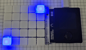
LED-Würfel: Zufallszahlen auf der Pixelmatrix darstellen

In meinem vorherigen Beitrag 'Pixelmatrix Combo von Oxocard: So programmierst du die 5×5 LED Matrix' habe ich bereits die Grundlagen und Möglichkeiten der Pixelmatrix vorgestellt. In diesem Beitrag möchte ich nun einen Schritt weiter gehen und zeigen, wie du mit der 5 × 5 LED Matrix einen digitalen Würfel programmierst, der Zufallszahlen anzeigt. Dieses Projekt eignet sich hervorragend, um die Programmierung von Zufallszahlen und die Ansteuerung der LEDs in einem kreativen Projekt zu kombinieren. https://youtu.be/RADOEflnNDs Hinweis: Dieses Produkt wurde mir vom Entwickler der Oxocard auf der Maker Faire 2024 in Hannover kostenlos zur Verfügung gestellt. Meine Meinung und Bewertung des Produkts basieren jedoch ausschließlich auf meinen eigenen Erfahrungen und sind unabhängig von dieser Bereitstellung.


Bezug der Pixelmatrix von Oxocard
Die in diesem Beitrag verwendete Pixelmatrix bekommst du für derzeit 49 CHF (ca. 52 €) unter https://oxocard.ch/. Zu dem Set gehört neben der Pixelmatrix noch der Mikrocontroller Oxocard Connect, welchen du für diese Cartridge benötigst. Rechts ist die Pixelmatrix Cartridge, da ich den Mikrocontroller bereits besitze, benötigte ich nicht das komplett Set.
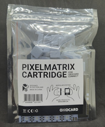
Pixelmatrix von Oxocard
Programmieren der Oxocard Connect in NanoPy
Den Mikrocontroller kannst du in NanoPy via Python programmieren. Die Entwicklungsumgebung NanoPy ist sehr leistungsstark und bietet für erfahrene Entwickler sehr viele nützliche Features, welches man in anderen Editoren für Mikrocontroller schmerzhaft vermisst, zum Beispiel ein Debugger.
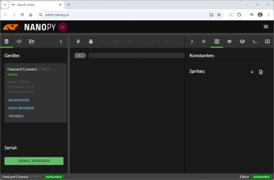
Editor - NanoPy für die Oxocard Connect Programmieren eines Würfels mit der Pixelmatrix & der Oxocard Connect Bevor wir mit der eigentlichen Programmierung starten, schauen wir uns an, wie man die Pixelmatrix programmiert. Jeder NeoPixel hat einen Index, welcher oben rechts beginnt und unten links endet.

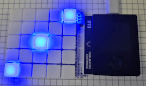
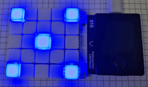
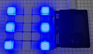
Anordnung der NeoPixel auf der Pixelmatrix Combo von Oxocard Mit der Funktion setDigitalLed können wir dann über diesen Index die LED ansteuern und einen RGB Wert übergeben. #aktivieren der LED mit Index 1 und setzen der Farbe blau setDigitalLed(1, 0, 0, 100) Theoretisch können wir jeden Farbwert verwenden, hier empfehle ich dir die Seite https://htmlcolorcodes.com/, auf welcher du recht einfach einen solchen Wert generieren kannst. Bitmaskieren der Zeilen Da wir die sechs möglichen Werte des Würfels auf der Pixelmatrix anzeigen wollen, gibt es hier mehrere Lösungen. Der wohl einfachste Weg ist ein Array mit 25 Werten für jeden Wert, das ergibt dann 6 Arrays welche wir je nach ermittelter Zufallszahl verwenden. Theoretisch spricht nichts gegen diese Lösung, denn es ist sehr unwahrscheinlich, dass ein neuer Wert hinzukommt, jedoch ist diese nicht optimal. Wir können auch jede Zeile in ein Bitmuster maskieren und so durch eine 0 und 1 den Zustand jedes NeoPixel abbilden. Im nachfolgenden Beispiel stelle ich die Augenzahl 1 dar, es sind alle NeoPixel deaktiviert außer das Mittlere in der dritten Zeile. digits = Wir benötigen zusätzlich noch eine Funktion, welche uns den Status des Neopixels liefert. Ich definiere hier, dass ein Bitmuster eine Zeile (in Englisch row) ist und als zusätzlichen Parameter übergebe ich den Index pro Zeile. Als Rückgabewert erhalte ich ein true, wenn der NeoPixel aktiviert werden soll, andernfalls ein false. def checkLed(row, index)->bool: return row & (1 bool: return row & (1 bool: return row & (1 Read the full article
0 notes
Text
Enlightening Spaces: Embracing the Versatility of LED Strip Lights

Dive into the world of limitless creativity with LED strip lights! These innovative lighting solutions are reshaping interior design, offering an array of vibrant colors and dynamic effects to illuminate any space with flair and personality. Whether you're enhancing your home decor, adding ambiance to your workspace, or accentuating architectural features, LED strips provide unmatched versatility and style. With their energy efficiency and easy installation, they're not just lights—they're catalysts for transforming ordinary spaces into extraordinary experiences. Embrace the versatility of LED strip lights and let your imagination shine!
Read more : https://www.ledstriplightings.com/ws2812b-sk6812-rgb-led-strip.html
0 notes
Note
I saw the post you did a while back about the electronic dice (firstly, super awesome and I love the way you got the random seeds).
I'm a computer science student but for the most part I only really do software. I have a raspberry pi pico and a breadboard but I've never been able to make it do more than light an LED, and I didn't understand how *that* worked. How do you get into that sort of thing? Or what was your path at least?
I started with software too, then I learned a bunch about mechanical and electrical stuff working on my car, and putting them together was kind of the obvious next step after that.
my early arduino projects were WS2812 LED things and simple single-motor contraptions. then in covid lockdown I built a 3D printer and my tinkering obsession amped up by several orders of magnitude.
11 notes
·
View notes
Text
chat is there open firmware for this yet? I would absolutely want to dedicate an afternoon to soldering up a nodemcu with some ws2812s for this

so it's happened

8K notes
·
View notes
Text
LED-Streifenlichter: Die Vielseitige Beleuchtung für Ihr Zuhause

LED-Streifenlichter sind eine moderne Beleuchtungslösung, die sich in den letzten Jahren immer größerer Beliebtheit erfreut hat. Diese flexiblen, energieeffizienten Leuchtstreifen bieten zahlreiche Vorteile und können in nahezu jedem Raum eingesetzt werden, um das Ambiente zu verändern oder funktionale Beleuchtung bereitzustellen. Ob für die Schaffung einer gemütlichen Atmosphäre oder als Akzentbeleuchtung – LED-Streifenlichter sind eine großartige Wahl, um Ihr Zuhause zu verschönern. In diesem Blogbeitrag erfahren Sie, warum LED-Streifenlichter so besonders sind und wie Sie sie in Ihrem Zuhause kreativ nutzen können.
Was sind LED-Streifenlichter?
LED-Streifenlichter bestehen aus kleinen LED-Glühbirnen, die auf einem flexiblen Band montiert sind. Diese Streifen sind in verschiedenen Längen und Farben erhältlich, viele Modelle bieten die Möglichkeit, die Farbe und Helligkeit per Fernbedienung oder App anzupassen. Durch ihre Flexibilität können sie an nahezu jeder Oberfläche installiert werden, sei es entlang von Wänden, unter Möbeln oder als dekorative Akzentbeleuchtung.
Der große Vorteil von LED-Streifenlichtern liegt in ihrer Vielseitigkeit. Sie sind perfekt für die Beleuchtung von schwer zugänglichen Stellen, an denen traditionelle Lampen nicht eingesetzt werden können, und bieten eine sanfte, indirekte Lichtquelle, die den Raum aufwertet.
Vorteile von LED-Streifenlichtern
Energieeffizienz
LED-Streifenlichter sind besonders energieeffizient. Sie verbrauchen deutlich weniger Strom als herkömmliche Glühbirnen und haben dabei eine vergleichbare oder sogar bessere Helligkeit. Dadurch helfen sie, die Stromrechnung zu senken und gleichzeitig den CO2-Ausstoß zu reduzieren.
Lange Lebensdauer
Ein weiterer großer Vorteil von LED-Streifenlichtern ist ihre Lebensdauer. Während herkömmliche Glühbirnen nach wenigen Tausend Stunden ersetzt werden müssen, können LEDs bis zu 50.000 Stunden halten, was sie zu einer äußerst langlebigen und kostengünstigen Lösung macht.
Vielseitigkeit
LED-Streifenlichter können in verschiedensten Anwendungen eingesetzt werden. Sie eignen sich sowohl für dekorative Zwecke als auch für funktionale Beleuchtung. Sie können beispielsweise unter Regalen, hinter Fernsehern oder entlang von Deckeninstallationen verwendet werden. Einige Modelle sind zudem wasserfest und für den Außenbereich geeignet, was ihre Vielseitigkeit noch weiter erhöht.
Einfache Installation
Die Installation von LED-Streifenlichtern ist unkompliziert. Die meisten Modelle haben eine selbstklebende Rückseite, die eine einfache Montage ohne Werkzeug ermöglicht. Sie können die Streifen an nahezu jeder Oberfläche befestigen und je nach Bedarf zuschneiden.
Kreative Anwendungen für LED-Streifenlichter Indirekte Beleuchtung Eine der beliebtesten Anwendungen für LED-Streifenlichter ist die indirekte Beleuchtung. Sie können hinter Möbeln oder entlang von Wänden installiert werden, um sanftes, diffuses Licht zu erzeugen, das den Raum aufwertet, ohne zu blenden.
Akzentbeleuchtung
Verwenden Sie LED-Streifenlichter, um bestimmte Bereiche oder Objekte hervorzuheben. Ob Regale, Kunstwerke oder besondere Möbelstücke – LED-Streifenlichter WS2812 LED-Streifenlicht können gezielt eingesetzt werden, um visuelle Akzente zu setzen.
Dekorative Beleuchtung für besondere Anlässe
LED-Streifenlichter eignen sich auch hervorragend für besondere Anlässe wie Partys, Feiern oder Feiertage. Mit der Möglichkeit, die Farben zu ändern, können Sie die Beleuchtung an den Anlass anpassen und eine festliche Atmosphäre schaffen.LED-Streifenlichter bieten eine moderne, energieeffiziente und vielseitige Beleuchtungslösung für Ihr Zuhause. Ihre Flexibilität, einfache Installation und lange Lebensdauer machen sie zu einer idealen Wahl für jeden Raum. Egal, ob Sie eine gemütliche Atmosphäre schaffen, Akzente setzen oder einfach eine funktionale Beleuchtung benötigen – LED-Streifenlichter sind die perfekte Wahl, um Ihre Räume aufzuhellen und zu verschönern.
0 notes
Text
GateFi 6 Channel Powered by ESP32: The Future of IoT Connectivity with 4G
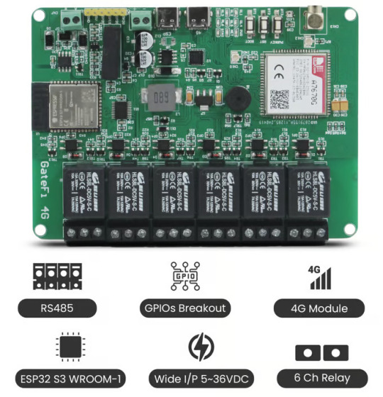
The rapidly advancing world of IoT (Internet of Things) and automation calls for devices that offer robust, flexible, and high-performance capabilities. The GateFi 6 Channel Powered by ESP32 with 4G Connectivity Microcontroller stands as a powerful solution for these needs, designed for industrial and commercial applications that demand reliable control, remote access, and seamless communication.
In this post, we will delve into the key features and capabilities that make the GateFi 6 Channel ESP32 S3 WROOM-1 an ideal choice for building smart systems with efficient relay control, fast connectivity, and advanced communication options.
What is GateFi 6 Channel Powered by ESP32 with 4G Connectivity?
The GateFi 6 Channel is a microcontroller designed to offer versatile and high-performance solutions for a wide range of IoT applications. Powered by the robust ESP32, a popular microcontroller that integrates Wi-Fi and Bluetooth capabilities, the GateFi 6 Channel is further enhanced with 4G connectivity. This combination ensures that your devices have seamless communication over the internet, even in areas where traditional Wi-Fi infrastructure might not be available or reliable.
This device can handle six independent channels simultaneously, making it ideal for tasks that require multiple communication points or data collection from various sensors, devices, or systems. The ESP32 ensures efficient processing and connectivity, while the 4G module guarantees that data can be transferred quickly and reliably over mobile networks.
Key Features
ESP32 S3 WROOM-1 Microcontroller: The ESP32 microcontroller is the heart of the GateFi 6 Channel. It provides a high processing power with dual-core capabilities, enabling fast data processing and communication. Additionally, the ESP32's Wi-Fi and Bluetooth support offer plenty of flexibility in local wireless communication.
6-Channel Relays with Optically Isolated Circuits: Comes equipped with 6 relay channels, which provide the ability to control a wide range of devices such as motors, alarms, or industrial machinery. These relays are optically isolated, offering protection against electrical surges and ensuring that high-voltage circuits are safely separated from the sensitive low-voltage control system. This isolation increases the reliability and longevity of your equipment, particularly in industrial applications where power spikes are common.
4G Connectivity with A7670G Module: The A7670G module provides 4G LTE connectivity, ensuring fast data transmission speeds even in remote areas with poor Wi-Fi coverage. This feature is perfect for applications like remote monitoring, data collection, and control over large distances. With the A7670G module, you can be confident in maintaining stable and fast communication, even in environments where traditional internet infrastructure might be lacking.
Visual and Audio Alerts: RGB WS2812 LED & Buzzer: The GateFi 6 Channel includes both RGB WS2812 LED and a buzzer for visual and audio alerts. The WS2812 LEDs can be programmed to display a variety of colors to indicate system status or trigger alerts. The buzzer, on the other hand, provides a sound notification for critical events, system errors, or triggered alarms. Together, these features ensure that operators and users are immediately informed about the state of the system.
Wide Voltage Range: 5V to 36V DC: Offers a flexible voltage range from 5V to 36V DC, making it suitable for various applications in both consumer and industrial settings. This wide input range means that the system can be integrated into a wide array of environments, from low-power consumer applications to high-voltage industrial equipment, without the need for additional power regulation.
RS485 Communication for Industrial Integration: The GateFi 6 Channel microcontroller includes RS485 communication support, enabling it to connect and communicate with other industrial equipment, sensors, or controllers over long distances. Whether it’s a smart factory, building automation system, or remote asset management, RS485 ensures reliable communication between devices even in noisy environments.
Interface Options: Dual Type C Ports: Offers two Type C ports—one for programming and one for 4G control. The Type C interface is becoming the industry standard due to its fast data transfer speed and reversible connector, making it easier to connect the system to various devices.
Connectivity: 2.4 GHz Wi-Fi and Bluetooth 5 (LE): Is well-equipped with 2.4 GHz Wi-Fi and Bluetooth 5 (LE) for local wireless communication. Whether you need to control the system through a mobile app, communicate with nearby devices, or connect to a cloud platform, the combination of Wi-Fi and Bluetooth 5 (LE) ensures a seamless and flexible communication experience.
Applications for GateFi 6 Channel Powered by ESP32
Industrial Automation
Smart Homes & Building Automation
Remote Monitoring & Control
Security Systems
Conclusion
The GateFi 6 Channel Powered by ESP32 by SB Components with 4G connectivity is a revolutionary device that brings powerful features to both industrial and residential automation. With its robust microcontroller, versatile relay channels, easy programming interface, and extensive connectivity options, the GateFi 6 Channel offers everything you need for efficient control and monitoring of various devices and systems.
Whether you’re upgrading your existing infrastructure or starting a new automation project, the GateFi 6 Channel is a solid investment for a smarter, more connected world.
#iot applications#iot#4g connectivity#gatefi6#innovation#relay board#electronics#technology#embedded systems#microcontrollers
0 notes
Text
Well, tonight was a bit of a learning experience; the ARGB controller that I picked up cannot handle more than 48 LEDs per string, which means that the 30 LED fans I have won't work with it at all; the mainboard will, in theory, support all 270 odd lights, but the vendor's software is... well, it's best described as a dumpster filled with fecal matter and on fire.
The only other 'free' applications that can talk to it properly (OpenRGB) does not see the mainboard controller, and does not talk to the ARGB controller I have properly, despite it being on the compatibility list. The only other free application, SImpleRGB, also doesn't cope with the fans correctly (probably due to that 48 LED limit) and also demands internet access on start up, and has a fixed window size of 1440 by 768, which is a bit of a pisser trying to navigate it on a 1280x1024 screen.
So, I guess I get to roll my own. Thankfully, I have just the thing already in house for a hardware controller, in the form of Adafruit's RP2040 SCORPIO Feather micocontroller, which has a theoretical limit of some 16 thousand WS2812 LEDs, across 8 parallel strings.
What I'm not happy about is having to pull the case apart YET AGAIN to extract one of the fans for testing and reverse engineering things as I program the controller; the ARGB "standard" is mostly WS2812 over the same three wire path (+5VDC, Data, and Ground), so even if I end up having to daisy chain all 9 fans into one giant string, I'll be covered, I think.
I just have to figure out what the internal order of the fans are for a given orientation and program the sequencing into the controller, and I can do that while I'm printing a housing for it so I don't have a bare board sitting inside the damn machine. (I'll probably need a SATA to 4 pin power adapter out of one of the other cable boxes in order to tap power for it, but such is life.)
And TBH, I'm probably going to release this setup out into the wild, because I've not found ANY good stand alone controller (or good software) that works on a near universal level.
Stay tuned, it's going to be... interesting.
0 notes
Link
Circuito mini árvore de Natal PCB com WS2812 https://te1.com.br/?p=45978 Por Toni Rodrigues Toni Eletrônica Circuitos...
0 notes
Text
The Technocolour Dreamcoat 3.0 beta
After ten years of faithful service, the Technocolour Dreamcoat 2.0 finally kicked the bucket. The silicone potting over the LED strips hardens over time and when the strip bends, the hardened silicone grips the LED chips and lifts them off the copper substrate. I replaced one glitchy strip and then identified the same problem in the neighbouring one, at which point I worked out was going on and realised it was futile.
So it was time to think about a redesign. This was great, as I’d get to incorporate a bunch of the ideas I’d had and new technology that had been released over the previous decade.
What needed improvement?
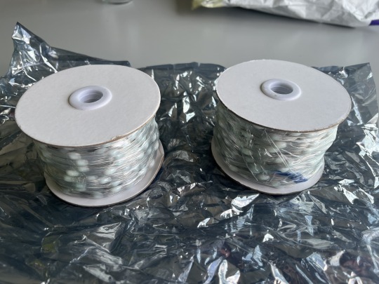
It turns out the silicone-potted strips have a lifespan. What’s new in the last few years are “pearl” LED strings which contain (I assume) 2020 WS2812 LEDs potted in little blobs of milky resin. These strings are much more flexible than strips and so will at least have a different failure mode (and I hope they’re significantly longer-lived.) They’re also light—important for a wearable!—and come in an interesting variety of pitches.
Another technology that didn’t exist a decade ago is the PixelBlaze. Don’t get me wrong, FastLED on a Teensy served me very well, but I’m not a huge fan of the “C++ in nose glasses” and “IDE that took a decade after the Retina MacBook Pro to catch on to Retina font rendering” aspects of the Arduino environment.
PixelBlaze also has a very interesting approach to LED mapping: patterns draw to a 0.0 to 1.0 line (or grid, or volume) of floats and the software re-maps that back out to the physical grid of pixels for your particular build. This means it natively supports non-regular pixel maps of arbitrary size from the same pattern code. It also supports 1-, 2- and 3D mappings, including cute arrangements like polar coordinates, which is useful for a piece like a jacket that’s essentially a cylinder. I thought that was worth trying for the trade of its “JavaScript in nose glasses” environment. More thoughts on how this tradeoff went later.
Finally, power. I was peaking at about 4A delivered by two USB batteries. But that is way, way less than what the LEDs themselves can take. I wanted the next version to be able to deliver all the power the LEDs could possibly consume at max brightness.
What worked well?
I briefly flirted with the idea of a new structure but after tearing the electronics off the jacket and washing it (for the first time in… um, let’s not say) I realised that was silly. The original jacket I’d commissioned from the fetish wear shop in Amsterdam[1] was too good a starting point to give up.
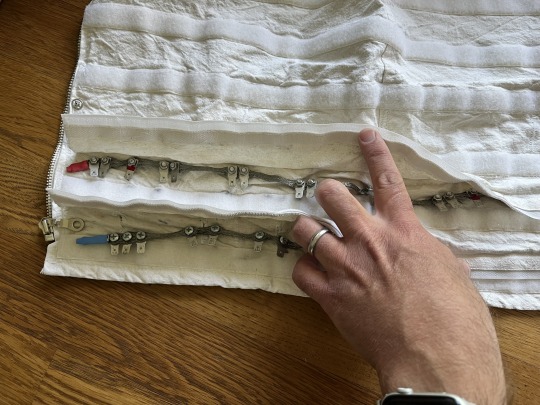
Another thing that really did hold up from the first design was the power bus. I’d had my fetish fashion designer friend run a couple of flaps right around the bottom of jacket, closed with Velcro. Through each of those I ran a length of braided copper ground strap with spade connector tabs bolted onto it (the positive bus is split in two, one half for each battery; the ground goes right around.) Wires soldered onto the LED strip’s positive and negative pads had spade connectors crimped on and connected to the appropriate power bus. This gave me a low resistance power bus and basically no voltage drop between the “first” and “last” strips.
Finally, I also liked having physical controls; namely a next/previous pattern button and a brightness pot. The PixelBlaze has a built-in web server for control, but “Wait a minute, I need to connect to my jacket’s wifi” is not something I ever wanted to have to say on the Playa.
The Design Process
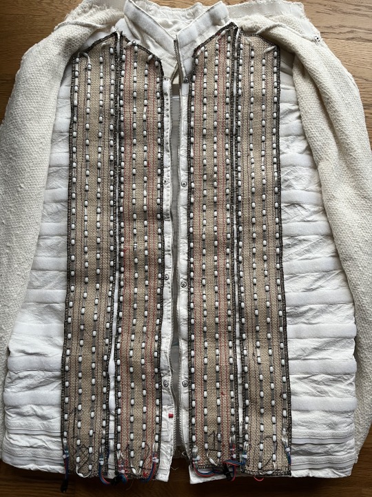
I ordered 1m of 50mm pitch pearl LED string to prototype with. After playing around with them and some graph paper, I decided 25mm pitch would be perfect if I offset them in alternating rows. This gives me equilateral triangles of not quite exactly 20mm per side (but close enough for government work) and a non-rectilinear arrangement which I find quite pleasing, plus a high, but workable density. Back-of-envelope calculations with the area of the jacket gets me to about 1400 pixels total with this arrangement.
Next problem was how to attach them to the jacket. The theory about Velcroing the strips to the jacket bottom layer so they could be removed for cleaning was sound, but in practice removing 32 individual strips (and unplugging their connectors) was so laborious I never did it. Plus, the pearl strings don’t really lend themselves to having Velcro attached to them. The docs for the strings (such as they are) recommend injecting power every 100-120 pixels or so and at my chosen density that’s four rows up and down the jacket from hem to collar. So I needed “panelise” the strings in lots of four columns somehow.
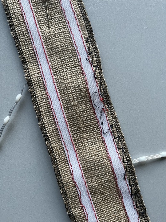
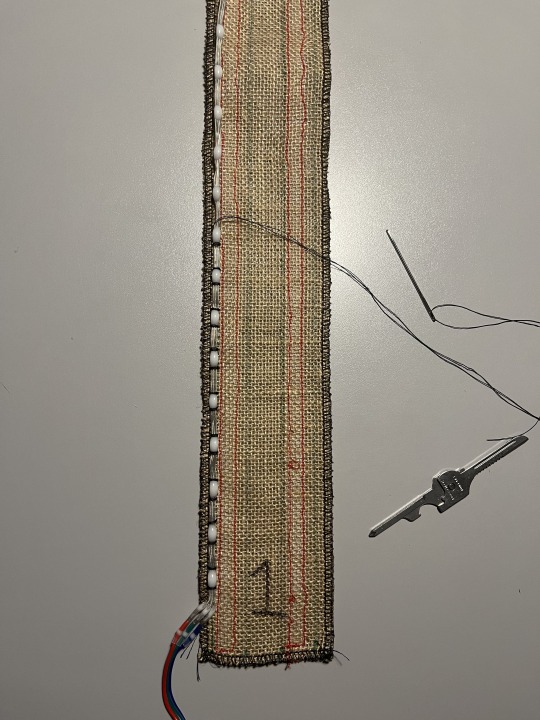
I could do this on strips of fabric with Velcro sewn to their backs, which I’d then sew the strings on the front of. For attaching the strings I initially shied away from sewing (because it’s not a skill I had heretofore developed) and tried using small zip ties. This didn’t work out well; it was as slow and laborious as sewing would have been and got you a bunch of sharp edges for your trouble (where you cut the tails of the ties off.) I chose hessian (burlap) as the substrate material, originally because I thought it would be easier to get the zip ties through, but it turns out it’s also amenable to sewing with a darning needle and stout thread. Another advantage is that it has a built-in “grid” that helps me keep my strings of LEDs straight and set my offsets correctly spaced.
The build
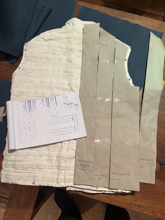
First I drew up paper patterns for all the panels; unsurprisingly one half of the jacket is a mirror image of the other so I only had to make six. Using these as templates I drew the panel outlines on the hessian then cut them out coarsely. I have access to an overlocker at my hackerspace, so I used this to hem the panels and trim them to size at the same time. Thank you to whoever had threaded and set the tension on the overlocker before I used it, it was pretty straightforward after testing out how it worked on some scraps first.

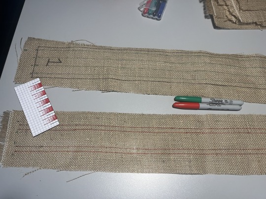
I arranged and numbered the panels flat out on the table, being double-triple careful to ensure I had everything the right way up given half of them were mirror images of the other half. Then I outlined two things: lines on the “top” of the panel, correctly-spaced for the rows of LEDs; and on the bottom two sets of “lanes” for the Velcro to be sewn in between. I had to experiment on paper first to get the spacing right as, given you can’t hand-sew through the Velcro, the LED lines and Velcro “lanes” had to be separated properly.
Next up was sewing the Velcro. This was a horrible job, considering that I’d forgotten absolutely everything I knew about using a sewing machine in the two decades or so since I’d last done it. Winding a bobbin, threading the goddamned thing, setting thread tension—I did all of these the hardest possible ways out of pure ignorance. Sewing Velcro isn’t easy either, but made less so by the Velcro I’d bought having hooks edge-to-edge with no “hem” to sew on up each side.
But with a lot of swearing I finally worked it all out and got it done. Next came attaching connectors to the LED string. I had a bunch of 3 pin JST connectors left over from a previous build but soldering them on would have been a massive pain. So I learned about the latest thing in butt connectors: solderless butt connectors! I ordered the smallest ones I could from Amazon and they turned out to be the perfect size to connect the tiny wires on the strings (32AWG?) to the much bulkier (~24AWG) tails on the JST connectors.
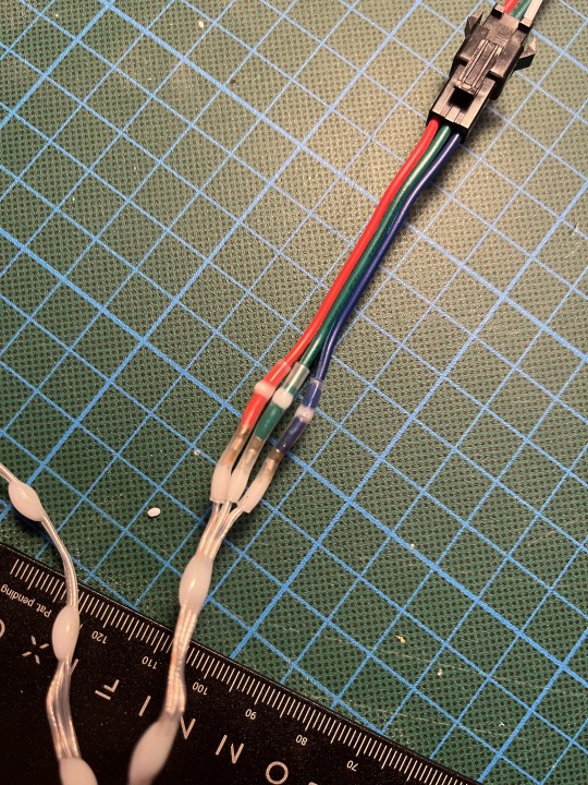
I soldered the female JST onto the start of the string, then sewed it onto the hessian from the reel until I got half way down the last row, at which point I’d know what my last LED would be so I could cut the string then solder on the other JST connector. Then sew down the rest of the row. The sewing is the tedious part and took the most time and swearing. You have two choices: tie on a short length of thread and have to tie it off and the new one back on quite frequently, or use a much longer thread and have it tangle on everything from the Velcro on the backs of the panels to the buttons on your shorts as you’re sewing. In the end I went with the longer thread and being careful[2], but I still don’t have a reliable knot for tying the start and end of the thread off on the hessian. Suggestions please.
The important (and deliberate) part about this design with the panels was that I could complete the whole piece in stages. As long as I had done at least two panels and stuck them either side of the zipper at the front, the piece would be presentable and I could test it in public. Indeed its first public appearance was in that form and I took it to Burning Man with only four panels finished.
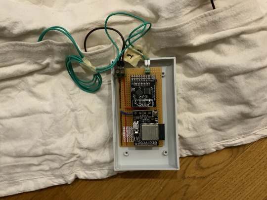
Then, there’s the control hardware and software. Available alongside the PixelBlaze controller itself is the output expander. It uses a serial protocol connection to the PixelBlaze controller and can output frames to each of the 8 connected strings simultaneously, greatly increasing your effective frame rate for 3-wire LEDs. My plan was to knock up a quick protoboard harness for the controller and expansion board and socket them in but that didn’t quite work out. The PixelBlaze pins aren’t breadboard-compatible and in addition, despite being the same sizes, the controller and expansion board’s power and RX/TX pins don’t line up. I’ve got to admit I found this kinda odd and it will make it more difficult than it needs to be when I ultimately have to design a proper PCB to mount them on alongside the power components.
But with some socket headers soldered at OCD-triggering angles I got it to basically fit together. Add some header terminals for power and signal and then it’s a Simple Matter Of Programming.
Actually before programming, there’s “mapping”. As I mentioned earlier, the PB software has a really interesting approach where patterns are programmed against an 0.0 to 1.0 line/area/volume and that’s mapped back out automatically to your actual pixel grid—which you have to specify. This can be done programmatically or by uploading a photo of your piece into a web tool and clicking on each LED, in order. This is tedious for 400-odd LEDs, but do-able.
You then take the mapping file (a JSON array of 2D points in my case) and upload it to the web interface the PixelBlaze serves. Its configuration pages can then show you previews of the various patterns that come preloaded with the system as they would look on your project. There’s a “playlist editor” where you can select which patterns will play in what sequence and with what delay, and you can edit the pattern code directly.
That is, you must edit the patten code directly. The editor is built into the interface the PixelBlaze serves over http. You can’t really create and preview a pattern on a computer then upload it to the PixelBlaze—you have to create and edit patterns on the PixelBlaze, which means you can’t effectively keep them under source control. I realise the target user might not be someone who is aware of the existence of git, but as someone who does software for a job it’s a bit of a drawback.
Next the control box. I soldered a couple of buttons and a potentiometer onto a little protoboard along with some pull-up resistors and designed a 3D printable case for it in ShapeScript (thanks to Nick for helping me out with how to do beveled edges!) Then I went to check out the APIs for changing patterns in PixelBlaze and they didn’t exist. There was only one way to change the pattern, and that was to press the button that was soldered onto the PixelBlaze board—or pull the pin it was connected to down to ground. Fortunately, Wizard was able to quickly add an API for me that allowed me to do what I wanted; I wired my buttons to some GPIO pins and everything worked great[3]!
And that’s the state it was in when it came with me to Burning Man. Unfortunately, I got one wear out of it before it started glitching out. From previous experience (it took a couple of outings to get the previous version to be reliable) I’ve determined that attempting to debug this kind of thing on-Playa is futile and not much fun, so I wore other pieces. At home I worked out that poking it in a particular place on the power bus would make it glitch but I couldn’t figure out why so I stripped the panels and power bus off and re-connected everything. It was better, but still not perfect, and for now I’m side-eyeing the power connection to the control box. Given the next phase requires a complete rebuild of that, I’m not too worried.
There are several more things to do before I’m going to count the hardware as “finished”: the most obvious is the grind of sewing and wiring the remaining eight panels. Once that’s done, I will work on…
MOAR POWER
I said earlier my goal was to be able to supply as much power as the final ~1400 LEDs would take. I know this is ridiculous but christ it’ll be cool[4]. I estimate it will draw in the region of 200W, which I plan to deliver from a couple of macho remote control car batteries bucked down to 5V via two 20A Murata OKL/T-20-W12 non-isolated DC-DC converters. I’ve had a good experience with the little siblings of these Murata parts before on another project and you just can’t get 100W out of USB battery banks—even USB-C PD ones generally top out at less than that, and even if you found one that did you’d be losing a significant amount of charge going from the internal cell voltage up to 20V then back down to 5V. However I seriously do not recommend anyone else attempt this. It’s a ridiculous idea, it’s not particularly safe, and 3A @ 5V is part of the USB-C PD spec which, times two (with a split positive rail[5]), is way more than enough to be obnoxiously bright in any situation. It’s entirely a stunt. But if I can pull it off you’ll be able to see me from space.
While we’re talking about power I wanted to note another quirk of PixelBlaze I wasn’t expecting: FastLED has a really neat feature where it will dynamically, every frame, scale the brightness of the output down to fit inside your specified power limit. It’s an estimate based on the type of LEDs you use so it’s not exact but it’s very very handy, especially for wearables. If you know your batteries can only deliver X amount of current, you can ensure your patterns are as bright as they could be without going over that. This is something which is apparently not possible due to some aspect of the design of the internals of PixelBlaze.
Anyway, to do all this I’ll need to design a custom circuit board to mount the PixelBlaze, the Output Expander, the sensor board, two Murata DC-DC converters (with edge-plated castellations), a power bus capable of delivering 20A, fuses in case it can’t and some kind of enclosure for all the above that won’t melt or set me alight. And KiCad and I don’t get along.
So that’s the state of the project right now! Hopefully I’ll see you—or more likely, you’ll see me—at Burning Man 2024.
[1] Walking past one day I saw a heavy canvas strait jacket in the window. Absent the arms and with the addition of Velcro strips sewn laterally around, it was perfect.
[2] Neutralising the hook Velcro by closing it with a strip of the loop Velcro helped, but I still ended up getting tangled at the ends of it.
[3] I added a little bit of debounce logic in software and it’s not 100% reliable, but good enough. Maybe I just need to tweak the constants, or maybe debounce is better done in hardware.
[4] I know, I know, it will be the absolute opposite of cool—even maxing out at 4A the old one got pretty warm to wear.
[5] This is very important; people warned me but my first design, where I linked the outputs of multiple USB battery packs together, fried four of them before I listened.
0 notes
Text
ESP32-S3-Zero: Kleine Größe, große Leistung – Ein Überblick

Als Technikbegeisterter bin ich immer auf der Suche nach neuen spannenden Mikrocontrollern, die mit ihrer Vielseitigkeit und Leistung überzeugen. Der ESP32-S3-Zero von Waveshare ist mir dabei sofort ins Auge gefallen. Dieser kleine Mikrocontroller steckt voller Power und bietet beeindruckende Features, die ihn perfekt für Projekte aller Art machen – von einfachen Bastelarbeiten bis hin zu anspruchsvollen IoT-Anwendungen. https://youtu.be/p1PegGIhx-M In diesem Beitrag möchte ich euch zeigen, wie der ESP32-S3 Zero aufgebaut ist und welche besonderen Funktionen ihn so einzigartig machen. Besonders faszinierend finde ich die Kombination aus Dual-Core-Prozessor, WiFi- und Bluetooth-Fähigkeiten sowie der Möglichkeit, KI-Anwendungen direkt auf dem Mikrocontroller auszuführen.


Damit das Ganze nicht nur Theorie bleibt, habe ich ein kleines Projekt vorbereitet, mit dem ich euch Schritt für Schritt erkläre, wie ihr den ESP32-S3 Zero programmieren könnt. Gemeinsam werden wir sehen, wie einfach es ist, mit diesem leistungsstarken Mikrocontroller Ideen zum Leben zu erwecken. Ich freue mich darauf, mit euch in die Welt des ESP32-S3 Zero einzutauchen!
Technische Daten & Features des ESP32-S3-ZERO
Technische Daten Der ESP32-S3 Zero überzeugt durch eine leistungsstarke Hardware, die ihn zu einem vielseitigen Mikrocontroller für unterschiedlichste Projekte macht. Mit seinem schnellen Dual-Core-Prozessor, umfangreichem Speicher und zahlreichen Schnittstellen bietet er alles, was für anspruchsvolle Anwendungen benötigt wird. Die folgende Tabelle gibt einen detaillierten Überblick über die wichtigsten technischen Spezifikationen. KategorieDetailsTechnische DatenProzessorXtensa® 32-bit LX7 Dual-Core, bis zu 240 MHz HauptfrequenzWi-FiUnterstützt 2,4 GHz Wi-Fi (802.11 b/g/n)Bluetooth®Bluetooth® 5 (LE)SpeicherEingebaute 512 KB SRAM und 384 KB ROM, onboard 4 MB Flash-Speicher und 2 MB PSRAMGPIO-Pins24 GPIO-Pins mit flexibler KonfigurationUnterstützte Schnittstellen4 × SPI, 2 × I²C, 3 × UART, 2 × I²S, 2 × ADCUSBIntegrierter USB-Seriell-Port-Controller (Full-Speed)StromversorgungEingangsspannung 3,7 V bis 6 VHardwarebeschreibungGPIO33 bis GPIO37 werden für Octal PSRAM verwendet und sind nicht zugänglichWS2812-AnschlussGPIO21 ist für die Verbindung mit der WS2812 RGB LED vorgesehenUART-PinsTX (GPIO43) und RX (GPIO44) als Standard UART0 Pins markiertFirmware-FlashFirmware erfordert das Halten der BOOT-Taste (GPIO0) während des Anschlusses des Type-C-Kabels Features Neben seiner beeindruckenden technischen Ausstattung punktet der ESP32-S3 Zero mit durchdachten Features, die ihn besonders benutzerfreundlich und effizient machen. Von energieeffizienten Steuerungsmöglichkeiten bis hin zur Unterstützung moderner Kommunikationsstandards – hier sind die Highlights auf einen Blick. FeaturesDetailsEnergieeffizienzUnterstützt flexible Taktrate und unabhängige Modul-Stromversorgung zur Realisierung von EnergiesparmodiAntenneOnboard-Keramikantenne, geeignet für direkte Lötung auf TrägerplatinenRGB LEDUnterstützt WS2812 RGB LED mit spezifischen GPIO-VerbindungenLow-Power-FunktionenVerschiedene Steuerungsmöglichkeiten für geringeren Stromverbrauch in verschiedenen Szenarien Unterschied - ESP32-S3-Zero & Zero M Der Mikrocontroller ESP32-S3-Zero ist in zwei Versionen erhältlich: die Standardausführung ohne Header (Stiftleisten) und die Variante ESP32-S3-Zero-M, bei der die Header vormontiert sind. Technisch unterscheiden sich die beiden Versionen nicht, sodass du je nach Bedarf und Projektanforderungen wählen kannst. Die ESP32-S3-Zero-M-Version mit vormontierten Headern ist ideal, wenn du deine Schaltung zunächst auf einem Breadboard entwickeln möchtest. Hast du dein Projekt fertiggestellt und möchtest es auf eine Platine (PCB) übertragen, bietet sich die Standardversion ESP32-S3-Zero ohne Header an. Diese erlaubt es dir, den Mikrocontroller direkt auf die Platine zu löten, was für eine kompaktere und robustere Umsetzung sorgt. So hast du die Flexibilität, den ESP32-S3-Zero perfekt an deinen Entwicklungsprozess und die Anforderungen deines Projekts anzupassen.
Bezug des ESP32-S3-Zero
Den kleinen Mikrocontroller bekommst du in den einschlägigen Elektronikshops wie Ebay, Amazon, AliExpress usw. jedoch unterscheiden sich hier die Preise enorm, daher empfehle ich dir einen tagesaktuellen Preisvergleich. - berrybase.de - 6,90 € - ebay.de* - ab 7,85 € - amazon.de* - ab 11,80 € - aliexpress.com - ab 3,89 € Hinweis von mir: Die mit einem Sternchen (*) markierten Links sind Affiliate-Links. Wenn du über diese Links einkaufst, erhalte ich eine kleine Provision, die dazu beiträgt, diesen Blog zu unterstützen. Der Preis für dich bleibt dabei unverändert. Vielen Dank für deine Unterstützung!
Pinout des ESP32-S3-Zero
Der kompakte Mikrocontroller ESP32-S3-Zero überzeugt mit seiner kleinen Platine von nur 18 mm x 23,5 mm. Trotz dieser geringen Größe bietet er stolze 40 Pins, die vielfältige Möglichkeiten zur Anbindung von Peripheriegeräten ermöglichen. Neben grundlegenden Schnittstellen wie I²C, SPI und UART sind an den Pins GP1 bis GP13 sowie GP17 und GP18 zusätzliche ADC-Funktionen verfügbar, sodass hier auch analoge Signale verarbeitet werden können. Diese Kombination aus Größe und Funktionalität macht den Mikrocontroller besonders attraktiv für vielseitige Projekte.
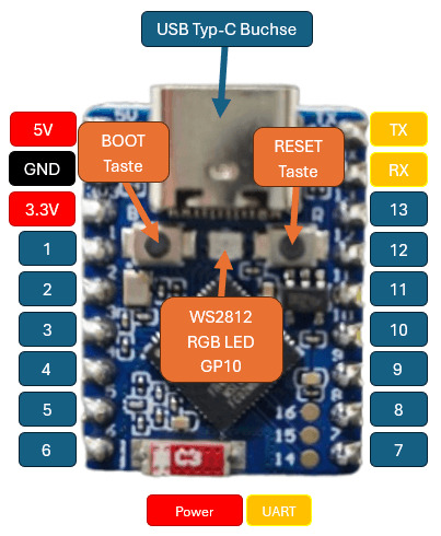
Aufbau - ESP32-S3-Zero Weitere Informationen zu diesem Mikrocontroller findest du in der offiziellen englischen Dokumentation unter https://www.waveshare.com/wiki/ESP32-S3-Zero.
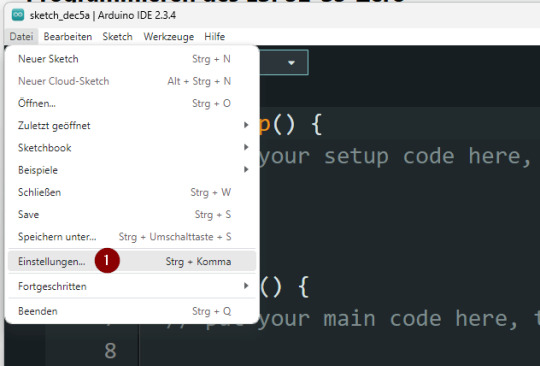
Programmieren des ESP32-S3-Zero
Wie bei den meisten ESP32-Mikrocontrollern stehen dir auch beim ESP32-S3-Zero verschiedene Möglichkeiten zur Programmierung offen. Du kannst ihn in der Arduino IDE, mit Espressif-Tools oder in MicroPython/CircuitPython programmieren. Ab Werk ist der Mikrocontroller bereits mit einer Firmware ausgestattet, die es dir ermöglicht, ihn in der Arduino IDE oder mit Espressif zu verwenden. Möchtest du hingegen mit MicroPython arbeiten, ist es notwendig, eine spezielle Firmware zu flashen. Keine Sorge, wie das funktioniert, erkläre ich dir Schritt für Schritt in dem oben verlinkten YouTube-Video. Arduino IDE Installieren des Boardtreibers Bevor wir mit der Programmierung beginnen können, müssen wir, soweit noch nicht geschehen, den Boardtreiber installieren. Dieser Treiber kommt mit dem Paket von Esspressif Systems, welches wir über die nachfolgende "Zusätzliche Boardverwalter URL" finden. https://raw.githubusercontent.com/espressif/arduino-esp32/gh-pages/package_esp32_index.json

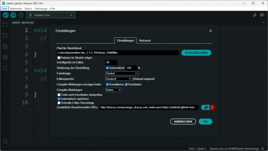
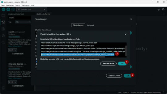
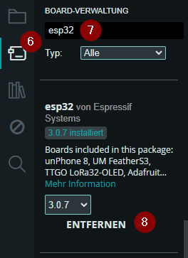
Anschließend kann man über den Boardverwalter (6) nach esp32 (7) suchen und aus den Suchergebnissen die Schaltfläche INSTALL (8) am Eintrag "esp32 von Espressif" klicken.
Auswahl und Konfiguration des ESP32-S3-Zero in der Arduino IDE Wie erwähnt, kommt mit dem Paket viele Treiber für diverse ESP32 Mikrocontroller. Aus dieser Liste wählen wir den Eintrag "ESP32S3 Dev Module" aus.

Arduino IDE - Auswahl des "ESP32S3 Dev Module " Anschließend wählen wir den COM-Port aus. (Natürlich sollte ab jetzt der Mikrocontroller mit dem PC verbunden sein!)

Arduino IDE - Auswahl des COM-Ports Für die Ausgabe der Daten auf der seriellen Schnittstelle müssen wir den Wert von "USB CDC On Boot" von Disabled (default) auf Enabled setzen.

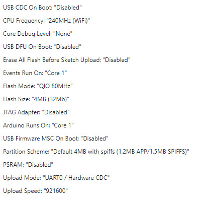
Rechts findest du die vollständige Konfiguration des ESP32-S3, so wie ich sie verwende. Dabei habe ich alle Werte auf ihre Standardwerte (Default) belassen, mit Ausnahme der Option "USB CDC ....", die ich individuell angepasst habe.

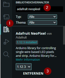
Programmieren der WS2812 RGB LED Lassen wir das übliche "Hello, World!" hinter uns und steigen direkt in ein spannenderes Projekt ein: die Programmierung der verbauten WS2812 RGB-LED, die am GPIO10 angeschlossen ist. Im standardmäßigen Programm, das automatisch startet, sobald du den Mikrocontroller an deinen PC anschließt, kannst du bereits einen Farbwechsel beobachten. Genau diesen Effekt wollen wir nun selbst programmieren und dabei die Funktionsweise der RGB-LED besser verstehen. Installieren der Adafruit NeoPixel Bibliothek Für das Programmieren der WS2812 NeoPixel verwende ich die Bibliothek Adafruit NeoPixel welche du entweder als ZIP-Datei vom GitHub Repository adafruit/Adafruit_NeoPixel herunterladen kannst, oder noch viel einfacher über den Bibliotheksverwalter der Arduino IDE.
Programmieren eines Farbwechsels an dem NeoPixel Programmieren wir also nun die WS2812 RGB LED. Diese ist am GPIO10 angeschlossen welchen wir programmatisch über den Pin 21 erreichen. Im Video siehst du den Farbwechsel von Rot über Grün zu Blau. Dabei ist die Helligkeit zunächst auf 50% eingestellt (das mag die Kamera deutlich besser). Auf der RGB LED kannst du theoretisch alle möglichen RGB Farben anzeigen. Das Problem ist hier bei kleinen Unterschieden das dieses nicht immer so sichtbar ist. Ich empfehle dir hier die Seite https://htmlcolorcodes.com/ wo du dir eine beliebige Farbe auswählen kannst und diese einfach in den Code kopierst. //Bibliothek zum ansteuern einer NeoPixel #include //Pin an welche die NeoPixels angeschlossen sind #define PIN 21 //Anzahl der NeoPixel #define NUMPIXELS 1 //Objektinstanz Adafruit_NeoPixel pixels(NUMPIXELS, PIN, NEO_GRBW + NEO_KHZ800); //Anzahl der Farben const int NUM_FARBEN = 3; //Array mit Farben uint32_t farben = { pixels.Color(0,255,0), //rot pixels.Color(255,0,0), //grün pixels.Color(0,0,255), //blau }; void setup() { //beginn der Kommunikation mit der NeoPixel pixels.begin(); //setzen der Helligkeit auf 50% pixels.setBrightness(50); } void loop() { //Schleife über die Farben for(int index=0;index Read the full article
0 notes
Text
Introducing Wearable Art with a Technological Twist: Electronic Earrings

Do you enjoy wearing jewelry? Do you have a strong interest in electronics as well? You're in for a treat if you checked both boxes. Let us present you with electronic earrings, a special example of how fashion and technology can come together.
Printed circuit boards PCBs, which serve as the foundation for the jewelry itself, were used in the creation of these amazing earrings. Eight WS2812 LEDs are neatly housed in a 2020 box inside each earphone. An ATtiny85 microcontroller that has been specifically configured to show a variety of eye-catching patterns manages these LEDs.
A tiny coin-cell battery that is neatly placed in a different PCB that is affixed to the back of each earring powers these earrings. Two tiny magnets do their magic to hold them firmly in place.
Let's examine the salient characteristics of these electronic earrings in more detail:
PCBs as the Core: The jewelry is cleverly built utilizing printed circuit boards, giving your look a creative and modern edge.
Mesmerizing LEDs: With eight WS2812 LEDs at your disposal, you can controllably create a breathtaking variety of patterns and effects.
Battery-Powered: Your earrings may be kept glowing brilliantly by using a little coin-cell battery.
Magnetic Hold: These earrings have a pair of tiny magnets that ensure they remain put as you attract attention everywhere you go.
Let's now assess the advantages and disadvantages of these intriguing accessories:
Advantages:
Innovatively Stylish: These electronic earrings make a strong fashion statement by elegantly fusing technology with your individual taste.
Easy to Make: Making your own earrings is a simple and enjoyable pastime that lets you express your creativity.
Affordable: These earrings are made very cheaply compared to many other jewelry options, providing a money-saving option for tech fans.
Disadvantages :
Carefully handle these earrings to prevent unintentional damage because of their fragile nature.
Because they are not intended to be water-resistant, keep in mind that these earrings are not appropriate for activities involving water.
Personal Preference: Although these earrings are unquestionably striking, not everyone will find them to be appealing in terms of taste or style.
#fashion#creativity#electronics#earrings#jewelrybusiness#jewelrymanufacturer#jewelrymaking#jewelrycaddesigner#jewelrydesigner
1 note
·
View note
Photo

Проект уехал в релиз #arduino #diy #ws2812b #ws2812 #esp8266 (at Lida) https://www.instagram.com/p/CnuOjpGIaXB/?igshid=NGJjMDIxMWI=
2 notes
·
View notes
Video
instagram
Light Driver Interactive light installation Concept by Hu Chin Hsiang(Peppercorns) feat. Barz LED design by 貢丸(Peppercorns) Web programming Hu Chin Hsiang(Peppercorns) Installation by 宗廷(穀米機工) Special thank: Lo He Ling, Iris
0 notes
Text
ESP32-S3-Zero: Kleine Größe, große Leistung – Ein Überblick

Als Technikbegeisterter bin ich immer auf der Suche nach neuen spannenden Mikrocontrollern, die mit ihrer Vielseitigkeit und Leistung überzeugen. Der ESP32-S3-Zero von Waveshare ist mir dabei sofort ins Auge gefallen. Dieser kleine Mikrocontroller steckt voller Power und bietet beeindruckende Features, die ihn perfekt für Projekte aller Art machen – von einfachen Bastelarbeiten bis hin zu anspruchsvollen IoT-Anwendungen. https://youtu.be/p1PegGIhx-M In diesem Beitrag möchte ich euch zeigen, wie der ESP32-S3 Zero aufgebaut ist und welche besonderen Funktionen ihn so einzigartig machen. Besonders faszinierend finde ich die Kombination aus Dual-Core-Prozessor, WiFi- und Bluetooth-Fähigkeiten sowie der Möglichkeit, KI-Anwendungen direkt auf dem Mikrocontroller auszuführen.


Damit das Ganze nicht nur Theorie bleibt, habe ich ein kleines Projekt vorbereitet, mit dem ich euch Schritt für Schritt erkläre, wie ihr den ESP32-S3 Zero programmieren könnt. Gemeinsam werden wir sehen, wie einfach es ist, mit diesem leistungsstarken Mikrocontroller Ideen zum Leben zu erwecken. Ich freue mich darauf, mit euch in die Welt des ESP32-S3 Zero einzutauchen!
Technische Daten & Features des ESP32-S3-ZERO
Technische Daten Der ESP32-S3 Zero überzeugt durch eine leistungsstarke Hardware, die ihn zu einem vielseitigen Mikrocontroller für unterschiedlichste Projekte macht. Mit seinem schnellen Dual-Core-Prozessor, umfangreichem Speicher und zahlreichen Schnittstellen bietet er alles, was für anspruchsvolle Anwendungen benötigt wird. Die folgende Tabelle gibt einen detaillierten Überblick über die wichtigsten technischen Spezifikationen. KategorieDetailsTechnische DatenProzessorXtensa® 32-bit LX7 Dual-Core, bis zu 240 MHz HauptfrequenzWi-FiUnterstützt 2,4 GHz Wi-Fi (802.11 b/g/n)Bluetooth®Bluetooth® 5 (LE)SpeicherEingebaute 512 KB SRAM und 384 KB ROM, onboard 4 MB Flash-Speicher und 2 MB PSRAMGPIO-Pins24 GPIO-Pins mit flexibler KonfigurationUnterstützte Schnittstellen4 × SPI, 2 × I²C, 3 × UART, 2 × I²S, 2 × ADCUSBIntegrierter USB-Seriell-Port-Controller (Full-Speed)StromversorgungEingangsspannung 3,7 V bis 6 VHardwarebeschreibungGPIO33 bis GPIO37 werden für Octal PSRAM verwendet und sind nicht zugänglichWS2812-AnschlussGPIO21 ist für die Verbindung mit der WS2812 RGB LED vorgesehenUART-PinsTX (GPIO43) und RX (GPIO44) als Standard UART0 Pins markiertFirmware-FlashFirmware erfordert das Halten der BOOT-Taste (GPIO0) während des Anschlusses des Type-C-Kabels Features Neben seiner beeindruckenden technischen Ausstattung punktet der ESP32-S3 Zero mit durchdachten Features, die ihn besonders benutzerfreundlich und effizient machen. Von energieeffizienten Steuerungsmöglichkeiten bis hin zur Unterstützung moderner Kommunikationsstandards – hier sind die Highlights auf einen Blick. FeaturesDetailsEnergieeffizienzUnterstützt flexible Taktrate und unabhängige Modul-Stromversorgung zur Realisierung von EnergiesparmodiAntenneOnboard-Keramikantenne, geeignet für direkte Lötung auf TrägerplatinenRGB LEDUnterstützt WS2812 RGB LED mit spezifischen GPIO-VerbindungenLow-Power-FunktionenVerschiedene Steuerungsmöglichkeiten für geringeren Stromverbrauch in verschiedenen Szenarien Unterschied - ESP32-S3-Zero & Zero M Der Mikrocontroller ESP32-S3-Zero ist in zwei Versionen erhältlich: die Standardausführung ohne Header (Stiftleisten) und die Variante ESP32-S3-Zero-M, bei der die Header vormontiert sind. Technisch unterscheiden sich die beiden Versionen nicht, sodass du je nach Bedarf und Projektanforderungen wählen kannst. Die ESP32-S3-Zero-M-Version mit vormontierten Headern ist ideal, wenn du deine Schaltung zunächst auf einem Breadboard entwickeln möchtest. Hast du dein Projekt fertiggestellt und möchtest es auf eine Platine (PCB) übertragen, bietet sich die Standardversion ESP32-S3-Zero ohne Header an. Diese erlaubt es dir, den Mikrocontroller direkt auf die Platine zu löten, was für eine kompaktere und robustere Umsetzung sorgt. So hast du die Flexibilität, den ESP32-S3-Zero perfekt an deinen Entwicklungsprozess und die Anforderungen deines Projekts anzupassen.
Bezug des ESP32-S3-Zero
Den kleinen Mikrocontroller bekommst du in den einschlägigen Elektronikshops wie Ebay, Amazon, AliExpress usw. jedoch unterscheiden sich hier die Preise enorm, daher empfehle ich dir einen tagesaktuellen Preisvergleich. - berrybase.de - 6,90 € - ebay.de* - ab 7,85 € - amazon.de* - ab 11,80 € - aliexpress.com - ab 3,89 € Hinweis von mir: Die mit einem Sternchen (*) markierten Links sind Affiliate-Links. Wenn du über diese Links einkaufst, erhalte ich eine kleine Provision, die dazu beiträgt, diesen Blog zu unterstützen. Der Preis für dich bleibt dabei unverändert. Vielen Dank für deine Unterstützung!
Pinout des ESP32-S3-Zero
Der kompakte Mikrocontroller ESP32-S3-Zero überzeugt mit seiner kleinen Platine von nur 18 mm x 23,5 mm. Trotz dieser geringen Größe bietet er stolze 40 Pins, die vielfältige Möglichkeiten zur Anbindung von Peripheriegeräten ermöglichen. Neben grundlegenden Schnittstellen wie I²C, SPI und UART sind an den Pins GP1 bis GP13 sowie GP17 und GP18 zusätzliche ADC-Funktionen verfügbar, sodass hier auch analoge Signale verarbeitet werden können. Diese Kombination aus Größe und Funktionalität macht den Mikrocontroller besonders attraktiv für vielseitige Projekte.

Aufbau - ESP32-S3-Zero Weitere Informationen zu diesem Mikrocontroller findest du in der offiziellen englischen Dokumentation unter https://www.waveshare.com/wiki/ESP32-S3-Zero.
Programmieren des ESP32-S3-Zero
Wie bei den meisten ESP32-Mikrocontrollern stehen dir auch beim ESP32-S3-Zero verschiedene Möglichkeiten zur Programmierung offen. Du kannst ihn in der Arduino IDE, mit Espressif-Tools oder in MicroPython/CircuitPython programmieren. Ab Werk ist der Mikrocontroller bereits mit einer Firmware ausgestattet, die es dir ermöglicht, ihn in der Arduino IDE oder mit Espressif zu verwenden. Möchtest du hingegen mit MicroPython arbeiten, ist es notwendig, eine spezielle Firmware zu flashen. Keine Sorge, wie das funktioniert, erkläre ich dir Schritt für Schritt in dem oben verlinkten YouTube-Video. Arduino IDE Installieren des Boardtreibers Bevor wir mit der Programmierung beginnen können, müssen wir, soweit noch nicht geschehen, den Boardtreiber installieren. Dieser Treiber kommt mit dem Paket von Esspressif Systems, welches wir über die nachfolgende "Zusätzliche Boardverwalter URL" finden. https://raw.githubusercontent.com/espressif/arduino-esp32/gh-pages/package_esp32_index.json


Anschließend kann man über den Boardverwalter (6) nach esp32 (7) suchen und aus den Suchergebnissen die Schaltfläche INSTALL (8) am Eintrag "esp32 von Espressif" klicken.

Auswahl und Konfiguration des ESP32-S3-Zero in der Arduino IDE Wie erwähnt, kommt mit dem Paket viele Treiber für diverse ESP32 Mikrocontroller. Aus dieser Liste wählen wir den Eintrag "ESP32S3 Dev Module" aus.

Arduino IDE - Auswahl des "ESP32S3 Dev Module " Anschließend wählen wir den COM-Port aus. (Natürlich sollte ab jetzt der Mikrocontroller mit dem PC verbunden sein!)
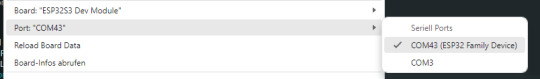
Arduino IDE - Auswahl des COM-Ports Für die Ausgabe der Daten auf der seriellen Schnittstelle müssen wir den Wert von "USB CDC On Boot" von Disabled (default) auf Enabled setzen.

Rechts findest du die vollständige Konfiguration des ESP32-S3, so wie ich sie verwende. Dabei habe ich alle Werte auf ihre Standardwerte (Default) belassen, mit Ausnahme der Option "USB CDC ....", die ich individuell angepasst habe.
Programmieren der WS2812 RGB LED Lassen wir das übliche "Hello, World!" hinter uns und steigen direkt in ein spannenderes Projekt ein: die Programmierung der verbauten WS2812 RGB-LED, die am GPIO10 angeschlossen ist. Im standardmäßigen Programm, das automatisch startet, sobald du den Mikrocontroller an deinen PC anschließt, kannst du bereits einen Farbwechsel beobachten. Genau diesen Effekt wollen wir nun selbst programmieren und dabei die Funktionsweise der RGB-LED besser verstehen. Installieren der Adafruit NeoPixel Bibliothek Für das Programmieren der WS2812 NeoPixel verwende ich die Bibliothek Adafruit NeoPixel welche du entweder als ZIP-Datei vom GitHub Repository adafruit/Adafruit_NeoPixel herunterladen kannst, oder noch viel einfacher über den Bibliotheksverwalter der Arduino IDE.

Programmieren eines Farbwechsels an dem NeoPixel Programmieren wir also nun die WS2812 RGB LED. Diese ist am GPIO10 angeschlossen welchen wir programmatisch über den Pin 21 erreichen. Im Video siehst du den Farbwechsel von Rot über Grün zu Blau. Dabei ist die Helligkeit zunächst auf 50% eingestellt (das mag die Kamera deutlich besser). Auf der RGB LED kannst du theoretisch alle möglichen RGB Farben anzeigen. Das Problem ist hier bei kleinen Unterschieden das dieses nicht immer so sichtbar ist. Ich empfehle dir hier die Seite https://htmlcolorcodes.com/ wo du dir eine beliebige Farbe auswählen kannst und diese einfach in den Code kopierst. //Bibliothek zum ansteuern einer NeoPixel #include //Pin an welche die NeoPixels angeschlossen sind #define PIN 21 //Anzahl der NeoPixel #define NUMPIXELS 1 //Objektinstanz Adafruit_NeoPixel pixels(NUMPIXELS, PIN, NEO_GRBW + NEO_KHZ800); //Anzahl der Farben const int NUM_FARBEN = 3; //Array mit Farben uint32_t farben = { pixels.Color(0,255,0), //rot pixels.Color(255,0,0), //grün pixels.Color(0,0,255), //blau }; void setup() { //beginn der Kommunikation mit der NeoPixel pixels.begin(); //setzen der Helligkeit auf 50% pixels.setBrightness(50); } void loop() { //Schleife über die Farben for(int index=0;index Read the full article
0 notes