#Which CAD Software is Best for Reverse engineering?
Explore tagged Tumblr posts
Visit Tumblr Blog
Explore Tumblr blogs with no restrictions, modern design and the best experience.
Last Seen Tumblr Blogs


Fun Fact
There are dozens of funny blogs to kill time on Tumblr.
Text
Which CAD Software is Best for Reverse engineering?
Reverse engineering typically involves the process of creating a 3D model or CAD representation of an existing object, often for purposes like modification, analysis, or reproduction. The choice of CAD software for reverse engineering can depend on various factors, including the specific requirements of the project, the type of data you're working with, and your level of expertise. Here are some popular CAD software options used for reverse engineering: Autodesk Fusion 360:
Fusion 360 is a comprehensive CAD, CAM, and CAE tool that includes features for reverse engineering. It supports importing point cloud data from 3D scans and converting it into a usable 3D model. Geomagic Design X (formerly Rapidform):
Geomagic Design X is a dedicated reverse engineering software that allows you to create parametric CAD models from 3D scan data. It is widely used in industries such as automotive, aerospace, and manufacturing.
Siemens NX:
Siemens NX offers powerful CAD and CAE capabilities, and it includes tools for reverse engineering. It supports importing point cloud data and converting it into usable surfaces and solids. Rhino 3D:
Rhino is a versatile 3D modeling software that is used in various industries, including industrial design and reverse engineering. It supports importing and processing point cloud data.
3DReshaper:
3DReshaper is a software suite that includes tools for processing and manipulating 3D point cloud data. It is often used in conjunction with other CAD software for reverse engineering applications.
CATIA: CATIA is a powerful CAD software widely used in the aerospace and automotive industries. It includes tools for reverse engineering, allowing users to work with scanned data and create parametric models.
Before selecting a CAD software for reverse engineering, it's essential to consider your specific project requirements, the type of input data you'll be working with (such as point clouds or mesh data), and your familiarity with the software. Additionally, ensure that you are using the software in compliance with licensing agreements and legal standards.
0 notes
Text
Everything you need to know about DWG Vs DXF
Anyone who works with Computer-Aided Design (CAD) software, will be familiar with two file formats: DWG and DXF.
To the untrained eye, these two formats may seem similar, but they are very different. This blog will talk about DWG and DXF formats and explore the similarities and differences between the two to help you understand which format fits your needs.
DWG and DXF file formats: An introduction
DWG and DXF are both file formats used in computer-aided design (CAD) software.
Let’s start with DWG.
DWG, which basically stands for “Drawing,” is a proprietary file format created by Autodesk, the company behind the popular CAD software AutoCAD. On the other hand, ‘DXF’, which stands for “Drawing Exchange Format,” is a non-proprietary file format created by the same company to allow for interoperability between different CAD software programs.
Both file formats are used to store 2D and 3D design data, but there are some key differences between them.
What are the similarities between DWG and DXF?
Although DWG and DXF differ, they do have common traits. Both formats are utilized in CAD software for storing 2D and 3D design information. They support vector graphics, enabling images to be resized without quality loss. Moreover, both formats allow editing within CAD software, facilitating seamless collaboration among designers and engineers.
What are the differences between DWG and DXF?
While DWG and DXF share some similarities, there are also key differences between the two file formats. The main difference is that DWG is a proprietary file format owned by Autodesk, while DXF is an open standard file format. This means that DWG files can only be opened and edited using Autodesk software, while DXF files can be opened and edited by a variety of CAD software programs. Additionally, DWG files tend to be larger in size than DXF files, which can impact file transfer and storage.
Which file format is better for specific applications?
The answer to this question depends on the specific application and the software being used. In general, DWG files are better for complex designs and projects that require precise measurements and accuracy. DXF files, on the other hand, are better for simpler designs and projects that don’t require as much precision. Additionally, DXF files are often used for sharing files between different CAD software programs, while DWG files are primarily used within the Autodesk software ecosystem. Ultimately, the best file format for a specific application will depend on the specific needs and requirements of the project.
How to convert DWG to DXF and vice versa.
Converting between DWG��and DXF file formats is a relatively simple process. Most CAD software programs have built-in conversion tools that allow users to easily convert between the two formats. To convert a DWG file to a DXF file, simply open the DWG file in your CAD software and then save it as a DXF file. To convert a DXF file to a DWG file, follow the same process in reverse. Keep in mind that some information may be lost during the conversion process, so it’s important to double-check the converted file to ensure that all necessary information has been retained.
Contact CAD Reprographics LLC to take advantage of PDF to DWG conversion services in Abu Dhabi and Dubai at our website cadreprographics.com
0 notes
Text
Technology Used in Steel Detailing
Today’s technology has taken over to simplify and diversify the work of Steel Detailing Companies in us. Today, manual drafting is no longer used in this industry, which was once run with pencils, pens, protractors, and subsequently calculators. The majority of detailers now use CAD, or computer-aided drafting. Steel detailers can express their creativity on a digital pad, which can then be reproduced as a 3D model or out on paper for 2D projects.
BIM in 3D technology
3D BIM is one of the newest technologies (Building Information Modelling). The 3D BIM software TEKLA is well-known in the field and has placed fourth in the last two years as a crucial and effective tool for the pre-engineered building sector. It can address any issue regions and is quicker than 2D detailing. After design is complete, modelling is done using BIM software. A list of raw materials, a dispatch list, shop floor plans for fabrication, etc. are sent once the model is finished.
For large projects, BIM is helpful in integrating important and essential services. Compared to 2D drafting, 3D models have several advantages.
It is simpler to implement changes and manage complex shapes.
Since all organisations involved in detailing, manufacturing, and erection follow the same model, there is little risk of misalignments occurring on project sites.
Software for nesting and site fabrication
The PEB business frequently and extensively uses site fabrication, yet there are better options available. High speed CNC plate cutting machines that use plasma or oxygen as fuel and nesting software to reduce scrap creation are available in PEB facilities. CNC punching and drilling are crucial for accurate site alignments and for creating holes for connections. Clips and other items can be welded using MIG equipment. Surfaces are prepared for painting using methods like shot and sand blasting.
CNC devices
C/Z purlins, roof and wall cladding are made using CNC cold roll forming equipment with auto pinching and shearing. Trims and accessories are produced by CNC folding machines. Other specialised equipment are employed in the production of various components, including anchor bolts, clips, and downtake pipes.
Designing Softwares
The majority of structural engineers conduct structural analysis using STAAD (from Bentley). The widely used and well-liked software MBS (Metal Building Software) provides the most accurate estimate, designing, and detailing of PEB buildings, together with shipping lists and 3D drawings. The PEB sector is now demonstrating its prowess in the construction of infrastructure, including high-rise and multi-story buildings, electricity transmission lines, metro tracks, and complicated constructions like airports.
There are some more internal softwares utilised for detailing in addition to MBS.
Benefits of Structural Steel Detailing Software
Employees in the structural steel sector possess a mastery of logic and reason as well as specialised training in all branches of mathematics.
The main advantage of using a Structural Steel Detailing Servicesis that the user gains further computer and programme knowledge. Once they have it down, trigonometry and geometry may be easily accessed without having to be memorised or manually calculated.
Why Having a 2D print version allows the steel detailer to provide a mock-up to the client before spending the time and money necessary to create a 3D representation. Any alterations or revisions made to the original blueprints are likewise recorded by the steel detailing programme. When input can be applied, the workflow is streamlined and the customer and creative can choose what works best for them both.
Using Structural Steel Detailing software decreases human mistake, promotes coherent brain-storming, and makes the process easier. Quick adjustments can be made instead of sketching numerous rounds, and maintained in notation in case there is a need to reverse back later.
The PEB industry is prepared and ready to take on a far larger role. The most cutting-edge technology are employed. The new airports serve as a superb illustration of PEB business. RCC structures have long dominated the housing market, but new PEB technologies are intended to displace RCC. The use of steel buildings with composite constructions can be significant in the provision of affordable housing for large numbers of people. Structural Steel Detailing Companieshas been employed in high rise structures, but the fact that it also presents fantastic opportunities in low and medium rise structures is a game-changer.
#structural steel detailing services#steel detailing companies in us#structural steel detailing companies in usa#top steel detailing companies in usa#structural steel detailing services in us
0 notes
Text
Rhinoceros software

#RHINOCEROS SOFTWARE SOFTWARE#
#RHINOCEROS SOFTWARE CODE#
#RHINOCEROS SOFTWARE WINDOWS#
OBJ file formats, both of which are supported by numerous 3D printers and 3D printing services. Rhinoceros 3D relies on a few plug-ins that facilitate 3D printing and allows the export of. From there, the user can control the vectors created in Rhinoceros, which can be enhanced further in Adobe Illustrator. The user starts by saving the file, then, when prompted, saves as Adobe Illustrator (*ai). This method is best when working with a vector-based file. Rhinoceros is also compatible with a number of graphic design-based programs. Rhinoceros 5 SR10 can import and export DWG/DXF file formats up to version 2014. Rhinoceros Service Releases (SR) are frequent and freely downloadable. Rhinoceros's import and export modules are actually plug-ins, so they can be easily updated via a service release. When Autodesk AutoCAD's file format changes (see DWG file format for more information), the Open Design Alliance reverse engineers the file format to allow these files to be loaded by other vendors' software. 3dm file format, Rhinoceros will convert the geometry into its native format when importing a CAD file, the geometry is added to the current file. When opening CAD file formats not in its native. The following CAD and image file formats are natively supported (without the use of external plug-ins):
#RHINOCEROS SOFTWARE SOFTWARE#
Rhinoceros offers compatibility with other software as it supports over 30 CAD file formats for importing and exporting.
#RHINOCEROS SOFTWARE WINDOWS#
NET 2.0 assemblies to read and write the file format on supported platforms – Windows, Windows 圆4, Mac, and Linux.
#RHINOCEROS SOFTWARE CODE#
An open-source toolkit, openNURBS includes the 3DM file format specification, documentation, C++ source code libraries and. The Rhino developers started the openNURBS Initiative to provide computer graphics software developers the tools to accurately transfer 3-D geometry between applications. The Rhinoceros file format (.3DM) is useful for the exchange of NURBS geometry. There are dozens of plug-ins available from both McNeil and other software companies that complement and expand Rhinoceros's capabilities in specific fields, such as rendering and animation, architecture, marine, jewelry, engineering, prototyping, and others. Rhinoceros's application architecture and open SDK make it modular and enable the user to customize the interface and create custom commands and menus. Rhinoceros is primarily a freeform surface modeler that utilizes the NURBS mathematical model. A visual scripting language add-on for Rhino, Grasshopper, is developed by Robert McNeil & Friends. Rhinoceros is developed for the Microsoft Windows operating system and macOS. jewelry design) as well as for multimedia and graphic design. automotive design, watercraft design), product design (e.g. Rhinoceros is used for computer-aided design (CAD), computer-aided manufacturing (CAM), rapid prototyping, 3D printing and reverse engineering in industries including architecture, industrial design (e.g. Rhinoceros geometry is based on the NURBS mathematical model, which focuses on producing mathematically precise representation of curves and freeform surfaces in computer graphics (as opposed to polygon mesh-based applications). Rhinoceros (typically abbreviated Rhino or Rhino3D) is a commercial 3D computer graphics and computer-aided design (CAD) application software that was developed by Robert McNeil & Friends, an American, privately held, and employee-owned company that was founded in 1969. December 8, 2020 20 months ago ( ) ģD computer graphics, Computer-aided design
0 notes
Text
General table solidworks 2014 download

General table solidworks 2014 download Activator#
General table solidworks 2014 download software#
General table solidworks 2014 download windows 8.1#
General table solidworks 2014 download download#
Simulate Multiple Design Scenarios Quickly evaluate the effects of various load combinations on a model, and tracking results. Designers and engineers can span multiple disciplines with ease, shortening the design cycle, increasing productivity and delivering innovative products to market faster.įocus On Design, Not Modelling with new features that reduce geometry creation steps.įaster Information Sharing Improved general performance, faster analysis and streamlined approaches give users the data to quickly make decisions and keep designing.Įnhanced User Experience An improved graphical interface presents a clear view of critical data to help focus on design. SOLIDWORKS solutions cover all aspects of your product development process with a seamless, integrated workflowdesign, verification, sustainable design, communication and data management.
General table solidworks 2014 download Activator#
This is not the entire program or application its just only the activator and keygenerator. This is a tool for activate any product of BS Dassault Systems wich of course include all products of solidworks and related tools.
Top Four Mistakes Made Interpreting Analysis Results - October 10, 2016.
Fasteners In FEA Dynamics Simulation - November 14, 2016.
SOLIDWORKS Add-In Basics For Stepping From Workgroup PDM To PDM - December 12, 2016.
For more tech tips and blog tutorials check out CAPINC's blog and videos.
General table solidworks 2014 download software#
We are the award winning 3D solutions partner offering SolidWorks software and training, and the entire Stratasys line of 3D printers and production systems. Our award winning technical support team is comprised of industry experts with hundreds of years of combined practical experience in mechanical design, design validation and analysis, product data management, and technical communication. CAPINC provides premier solutions and services in New England to assist our customers in accelerating their design and development process for better mechanical products. Adobe After Effects CC 2018 v15.CAPINC was founded on one core principle: Provide the best solutions and services to assist our customers in designing and developing better products.
General table solidworks 2014 download download#
Adobe Master Collection CC 2020 (圆4) freeload.If you have any software requests, you can post it in our Request Section.Enjoy and bookmark our website GetIntoPc, visit us daily for the latest and quality downloads.After a few seconds your Your Download will start automatically.On the next page, wait for a few seconds.Click the download button below and you will be redirected to the next page.
General table solidworks 2014 download windows 8.1#
OS: Windows 8.1 / Win 8 / Win 7 / Vista.
System Requirements For Solidworks Premium 2014 Software Before you install Solidworks Premium 2014 Software you need to know if your system meets recommended or minimum system requirements
Test against real life motion and force.
Enhanced Reverse Engineering Capabilities.
The reverse engineering capabilities are also added in Solidworks premium 2014 software.įeatures of Solidworks Premium 2014 Below are some noticeable features which you’ll experience after Solidworks Premium 2014 freeload Recently the pipe routing facility is added which is a big plus. Also its latest data validation tools helps to keep industry best practices. It has powerful simulation tools which help to simulate every type of 3D CAD design.
0 notes
Text
System76 and LVFS - What Really Happened
Wednesday there was an unfortunate message posted from Richard Hughes regarding his firmware service.
As a company, we really try to focus our energies on positive progress in building open hardware. It’s important to us to set a good example for how an open community should collaborate. When this message was posted, we originally took the stance of not refuting the articles’ gross misrepresentations. However, this article has caused some confusion with our customers.
When we reached out to Richard over a year ago, we were enthusiastic about LVFS and interested in whether or not it would work for us. Once we described how we needed to deliver firmware, we were told that it would not work well and would likely not be acceptable to Red Hat Legal.
System76: Yes, AFUEFI [a firmware flashing tool] is proprietary. We could distribute it in binary format, as part of the cab in LVFS. What we need to flash is for a simple, open source, piece of EFI code to run the extracted AFUEFI executable with the correct parameters. The EC would also be flashed with a similar tool. If desired, we can package it all up into a single EFI executable to be run by fwupd on reboot. The method we are currently using is to bless a new EFI binary (currently a UEFI shell) and reboot to it, then it runs a script that does the flashing, and then removes itself as a boot option.
Richard Hughes: I don't think this will work well; for a few reasons: * there's no way to reference a flashing tool in the XML, or to sign a executable on the LVFS * I don't think Red Hat legal will like the idea of shipping the flashing program, we've only ever talked about the firmware files themselves (although I concede the images in the .cap are probably firmware executable code wrapped up in layers). * I know the Red Hat security team will do more than blink when we tell them we want to ship a untrusted nonfree binary which would get run as root on RHEL on customer machines.
There is no other way to interpret this email other than LVFS won’t work well for us. UpdateCapsule is not supported by over a decade of machines in the field and could not be added without a firmware update. With UpdateCapsule, the vendor’s proprietary update software is still present (with the same security considerations) but is integrated into the firmware blob. This is less modular than our approach, and does not allow the reverse engineering and open-sourcing of firmware update components.
So we can’t use LVFS for BIOS. Maybe the EC? We experimented with flashing the EC from user space. The keyboard is connected to the same device and would freeze during the update process. The experience was suboptimal and not up to our standards.
Delivering automatic updates to customers is important for our customer’s security and our ability to constantly improve computers. We continued to experiment. In about a week or two we had a working proof of concept that delivered the BIOS and EC reliably and securely. Over the next months we improved the tool, added unique blockchain security infrastructure, moved it into laptop production and then out to customers.
The decision making is simple. We are told we can’t distribute the tool we need in LVFS. Flashing the EC in user space is suboptimal. And in any case managing separate repos for two components that work together is error prone. And we have a working prototype. Soon thereafter we were shipping firmware built on secure infrastructure out to customers. Thanks to this work we were able to quickly and automatically patch computers when the Intel ME vulnerability arrived, and we have a battle-tested system in place for the future.
LVFS Misrepresentations
The statement that claims our firmware tool only works on Pop!_OS is not true. System76 computers ship with Pop!_OS and Ubuntu, and both include automatic firmware updates. All Ubuntu based distributions are supported. We’ve had customers with Arch use our firmware update tool. We’ll officially support more distributions as time permits.
Our conversations were completely misrepresented and distorted in a way that was designed to make us appear as though we made the decision not to use LVFS rather than the truth - there were several conversations to try to implement this, followed by many roadblocks, and then we were told “I don't think this will work well.”
We engaged with the project in good faith. When it was determined that LVFS would not work for our needs, we built an open source tool that would provide the necessary functionality for our customers. Having a collaborative conversation about how to use existing tools, then needing to build an open tool that best fits your needs should never result the way this conversation did.
System76 and GNOME
It's unfortunate this appeared on the GNOME blog, but it only represents one person—not the GNOME community as a whole, nor our relationship with GNOME. We couldn't be more excited about our shared future with the GNOME project and working together to advance the free and open source desktop.
The Future of Firmware
LVFS and UpdateCapsule might be okay for companies mostly focused on a proprietary future (Logitech, Dell, etc.). UpdateCapsule is not the technique companies will use in a future of open source firmware—the future we’re working toward.
Liberating firmware is going to be a long and challenging process. Much like Free Software has replaced proprietary software over time, we must chip away at the proprietary firmware pieces within the hardware supply chain. Manufacturing is the first step. This year we’ll manufacture open source desktop designs in our Denver plant. The CAD will be free to download, change, and produce.
There will be a separate, open source electrical design and open source firmware daughter board to control functions within the desktop. On a mainboard there is the BIOS chip and one or more embedded controllers that manage fans, keyboard, LEDs, hotkeys and other critical functions. It’s all proprietary. Our strategy is to move this functionality from the proprietary mainboard to the open source daughter board. Then anyone can create a PCB with basic computer functionality, understand how it works, and improve upon the work. One could have this PCB made at Osh Park, install it in their desktop, tune it, and replace a bunch of proprietary firmware instantly. We’ll grow from there.
Slowly we’ll chip away at more and more of the mainboard functions until what’s left is Intel and AMD bits. Then there’s the challenge of convincing them to go open. There’s room for cautious optimism.
On Open Source and Community
There are thousands of open source projects led by smart and supportive people that are kind to each other and good to work with. Open Source as a community gets a bad rap at times. Projects that attempt to bully others into saluting their flag are the exception. We choose to support those that want to build things and those that encourage others to build things. Go GNOME, go KDE, go i3, go Solus, go elementary OS, go Kdenlive, go OpenShot, go, go, go! Let’s just make things. Don't worry about saluting one flag over another. Do what is right for you and your project. The premise of “NIH” is antithesis of open source.
Now, we’re off to build a factory to manufacture open source computers. Oh, and when you buy a System76 computer, you support people actually working to liberate the computer.
17 notes
·
View notes
Text
Why you should learn DelCam?

Introduction
DelCam is a licit supplier of advanced CAD/CAM software that is extensively utilized in the manufacturing industry. To be precise, you will find this software providing you with solutions on Microsoft Windows. DelCam will also help you in the whole designing procedure of 3D complicated models using surfaces, solids, and triangles. In recent years, this specific software will assist you in the transferring of 3D point cloud data to reverse engineer 3D models. Its 5-axis feature makes it worth utilizing. And that's why recently, candidates seem to be more interested in the DelCam Online Training in India course. Moreover, it also has a bright future ahead.
Let’s now proceed further, and have a look at some of the reasons to learn this course.
Reasons to learn DelCam
Well, DelCam comprises of some exceptional features like no other contemporaries, and that's why it's sustaining in this direction.
One of the significant benefits of DelCam is that it will provide you with shorter cutters since the head of the device tool can be lowered towards the job and the cutter oriented towards the surface.
In fact, its 3-axis machine also helps you in deep pockets that can only be utilized by expanding the length of the cutter basically.
Furthermore, this specific technology will also help you with dealing with complex shapes in a single set-up.
Moreover, this device will save you time, and unnecessary costs.
Acquiring a proper accreditation of this course will help you in turn into a VMC DelCam Developer.
Having this specific accreditation in hand, you will be able to grab one of the highest salary structures in hand.
By enrolling in its professional course, you will get a detailed understanding of Power Mill, and how to implement it effectively as well.
The listed information highlights the main importance of utilizing this technology. If you still want to acquire a detailed information of this course, then you should enroll in its professional course.
Which is the best way to acquire DelCam training?
To be honest, there are numerous ways to accumulate information concerning this course. But you should always select the best ones for your career. And getting in touch with an institution will be a suitable way to obtain its legitimate training. Yes, an educational body will help you to understand this subject right from the scratch.
In fact, faculty members present in the institution will help you in providing the utmost correct information concerning customizing Power MILL Stock Models, defining Work planes, Machining simulation, Data exchange, and in creating process sheet Setup for machining, etc. You will also acquire its practical implementation as well.
Conclusion
The suggested information highlights the importance of DelCam. If you also want to construct your career in this line, then you should obtain a licit certification of DelCam Online Course in hand. Post acquiring this accreditation, you will gradually receive more job opportunities. In fact, acquiring a proper understanding of this course will help you lifetime if you decide to stick to this field in the long run.
1 note
·
View note
Text
Mac Free Diagram Software

This best free drawing software includes different “soft” and “hard” brushes with variable features, the possibility of layer-by-layer drawing processing, smoothing and other effects, as well as a large number of additional tools. Corel Painter Completely free drawing software for professional digital drawing. Belight live interior 3D Mac is an amazing free interior design software for Mac for you to curate and manifest your dream interior design, professionally and personally. This software helps you in designing the interiors of your home in 3D and its interface is user-friendly which allows you to dive into the ideas more easily. Top reasons SmartDraw is the best diagram software: Click simple commands and SmartDraw builds your diagram for you, automatically. Add or remove an element, and SmartDraw realigns and arranges everything automatically for great results every time. Hundreds of professionally designed diagram templates and examples make you instantly productive. Best Architectural CAD Software for Mac. Explore these highest-rated tools to discover the best option for your business. Based on ratings and number of reviews, Capterra users give these tools a thumbs up. Select a product to learn more. AutoCAD Architecture, BricsCAD, SketchUp, ZWCAD, ARCHICAD, PaleBlue, Cad Cabin Home Designer.
ConceptDraw DIAGRAM is a famous Entity Relationship Diagram software for MacOS which gives the ability to describe visually the databases using the Chen’s notation icons and Crow’s Foot notation icons for drawing ER diagram (ERD). Entity Relationship Diagram Software for Mac. Find and compare top Diagram software on Capterra, with our free and interactive tool. Quickly browse through hundreds of Diagram tools and systems and narrow down your top choices. Filter by popular features, pricing options, number of users, and read reviews from real users and find a tool that fits your needs. Diagram tool Rubber Stamp Tool Style brush tool Interface: Mac: iOS: Dark mode Document browser in iOS 13 Multiple windows in iOS 13 Drag-and-drop Smart guides Manual guides Touch Bar support Flexible inspectors Workspaces Keyboard shortcuts Share customized keyboard shortcut sets Import and export: Mac: iOS: Insert common image formats.
The free SQL tool of choice for me is SQuirreLSQL. It is a Java application, but very responsive, and you can install both DB drivers and plugins from it, and one of them allows for reverse-engineering and diagramming databases.

Includes a free 14-day trial
Drawing ER diagrams on a Mac is smooth and easy when you have a software tool well-suited for professional ERD drawing. ConceptDraw DIAGRAM software for Mac extended with the Entity-Relationship Diagram (ERD) solution is the best tool for drawing ER diagrams on a Mac. Drawing ER diagrams on a Mac.
With the power to diagram, rapid-prototype, and design, OmniGraffle was made for professionals who need to organize or communicate visually—beautifully.
Diagramming
OmniGraffle is purpose-built for explaining complicated ideas in a beautiful, precise way.
Rapid-prototyping
Quickly create beautiful wireframes to explore ideas accurately.
Design
Powerful tools for creating professional-grade vector graphics.
Smartdraw Free Download For Mac
Er Diagram Software For Mac Os
Diagramming
Your browser does not support the video tag.

Er Diagram Software For Mac Computers
OmniGraffle is purpose-built for explaining complicated ideas in a beautiful, precise way.
Rapid-prototyping
Your browser does not support the video tag.
Er Diagram Software For Mac Windows 10

Quickly create beautiful wireframes to explore ideas accurately.
Design
Your browser does not support the video tag.
Powerful tools for creating professional-grade vector graphics.
Intelligent grouping, snapping, and alignment tools allow you to move quickly, without sacrificing accuracy or quality.
Er Diagram Software For Mac Operating System
Organize, communicate, and share your ideas with stunning visuals.
Er Diagram Software For Mac Catalina
Free Workflow Diagram Software Mac
Mac, iPad, and iPhone can all share the same stencils, projects, and JavaScript automation, allowing you to quickly create or edit a diagram from anywhere.
Network Diagram Software Mac Free
Comments are closed.
0 notes
Link
SOLIDWORKS 3D CAD Standard or Professional? Which 3D design product is best for you? Each year, SOLIDWORKS makes changes and additions to its products. With each upgrade, SOLIDWORKS 3D design products make the lives of design engineers easier. The three SOLIDWORKS 3D CAD products – Standard, Professional, and Premium, are full with features. But which product will best suit your needs? Might you be better off sticking to the SOLIDWORKS 3D CAD Standard or upgrading to a Professional package? Here we will look at the variations between SOLIDWORKS 3D CAD Standard and Professional. But first, let’s begin on the very starting – what’s the hype around SOLIDWORKS? Why is it considered one of the best 3D design products available today?
What is SOLIDWORKS?
SOLIDWORKS is a solid modeling computer-aided design (CAD) and computer-aided engineering (CAE) computer program published by Dassault Systèmes, that runs primarily on Microsoft Windows. According to the publisher, more than two million engineers and designers at more than 165,000 companies are using SOLIDWORKS. (Source) SOLIDWORKS 3D design products include Standard, Professional, and Premium. The difference between the three products is how they can benefit your business. Here we will look at the differences between SOLIDWORKS 3D CAD Standard and Professional software.
SOLIDWORKS 3D CAD Standard
SOLIDWORKS Standard is a 3D design product that gives you superb performance and 3D design capabilities. The easy-to-use software allows the creation of detailed components and assemblies and production-level drawings. If you want to create structural welded assemblies, complex surfaces, or metal flat patterns, the software allows you to do this. Standard features include: • SOLIDWORKS 3D CAD • Part and Assembly Modeling • 2D Drawings • Design Reuse and Automation • Collaborate and Share CAD Data • Interference Check • First-Pass Analysis Tools • CAM Programming (SOLIDWORKS CAM) • Design for Manufacturing (DFM) • Productivity Tools • Advanced CAD File Import/Export and 3D Interconnect • Xtended Reality (XR) Exporter
SOLIDWORKS 3D CAD Professional
SOLIDWORKS 3D CAD Professional builds on the capabilities of SOLIDWORKS Standard with ECAD/MCAD collaboration, collaboration capabilities, automated cost estimation, sophisticated components, and parts library, design and drawing checking, and advanced photorealistic rendering. As well as including all the features of SOLIDWORKS Standard, SOLIDWORKS Professional has the following features: • CAD Libraries (SOLIDWORKS Toolbox) • Design for Cost (SOLIDWORKS Costing) • ECAD/MCAD Collaboration (CircuitWorks) • CAD Standards Checking (Design Checker) • Collaboration with eDrawings Professional • Automated Tolerance Stack-Up Analysis (TolAnalyst) • Advanced Photorealistic Rendering (SOLIDWORKS Visualize) • SOLIDWORKS File Management • Reverse Engineering (ScanTo3D) SOLIDWORKS 3D CAD Professional’s integrated suite of tools enables you to get your job done much quicker when you want to take your product development capabilities to the next level. You can: • Save time by avoiding redesigns, fixing issues, and reducing mistakes. • Have more control over the design process. • Automatically estimate manufacturing costs. • Convert imported geometry. • Search for design errors. • Securely store all your project information. • Track all design changes. • Bring your products to life with integrated visualization.
Which SOLIDWORKS 3D CAD product is best for you?
When you want to get up to speed fast, the SOLIDWORKS 3D CAD Standard product is your best bet. The SOLIDWORKS 3D CAD Standard has all the core capabilities of the SOLIDWORKS software and is designed for the designer who, at the most, needs core drawing and part assembly capabilities. SOLIDWORKS 3D CAD Professional has several upgraded features for advanced accuracy and efficiency. It’s far designed for regular users who want to increase productivity, get through their work quicker and greater efficiently at the same time as simultaneously saving time. • For multi-employee organizations, SOLIDWORKS 3D CAD Professional’s tools can realistically meet theirs and the company’s needs. • To fulfill challenges beyond engineering and design. For example, when you need to enhance your marketing/sales pitch, SOLIDWORKS Visualize and eDrawings Professional (included in SOLIDWORKS Professional) assist you to create simply actual and high-quality photo-renderings of your products. • When you want to decrease time to marketplace. • If you want a better way to manage data go with the flow. • To better communicate your design thoughts to stakeholders. • Show customers and stakeholders your designs on their devices – even though they don’t have SOLIDWORKS. Every organization wishes software capabilities that allow it to grow today as well as tomorrow. So, it is important to select the perfect SOLIDWORKS 3D design product that fulfills your requirements. If you are familiar with SOLIDWORKS 3D CAD software and want to increase your workflow and output, you can benefit from the SOLIDWORKS 3D CAD Professional version. However, if you are a casual user who does no longer uses SOLIDWORKS each day or is not familiar with the software, SOLIDWORKS Standard will be best for you. Engineering Technique is a SOLIDWORKS authorized reseller in Gujarat, India made up of qualified and experienced engineers who provide sophisticated 3D design software solutions for engineers.
Originally Published at Engineering Technique Blog.
0 notes
Text
The first step in making molds - How to modeling plastic products
With the rapid development of computer technology today, three-dimensional geometric modeling technology has been widely used in the manufacturing industry in all aspects of product and mold design, program review, automated manufacturing, and management and maintenance. The technical data we receive from upstream manufacturers may be three-dimensional models of various data types. However, due to various reasons, what we are facing may not be CAD models, but real samples. Sometimes, Even a reference drawing does not exist, which brings us a great obstacle to adopting advanced design methods and advanced manufacturing technologies in our subsequent work. We must use various measurement methods and three-dimensional geometric modeling. The method is to transform the original object into a three-dimensional digital model on the computer. In the field of CAD, this is the so-called reverse engineering technology.
Copying is the Guangdong common name for reverse engineering, and it is called modeling in Jiangsu and Zhejiang. It is often used in imitation work. It is the reverse process of design in the usual sense. That is, the laser machine is used to scan the existing model to obtain the three-dimensional contour data, and the professional reverse engineering software is used to reconstruct the model, and finally the CNC program is generated, and the CNC processing is performed.
Heya use 3D measuring machine to get accurate dimensions based on the provided samples. If you need to make same, that's no problem. Our designers also can make three dimensional designs according to your sketch or 2D drawings. Everything will be updated to you, until you say it is ok. Our experienced plastic mould designers make all mould designs with the best optimized mold water channel arrangement and the best cycle time performance consideration.
If you have any new mould projects, welcome to contact by whatsapp or mob:8613867644770
#3Ddesign #plasticmolddesign #molding #modeling #copying #plasticproducts #design #plasticmolds #injectionmoulds
0 notes
Text
Edrawings 2019 Download For Mac

Edrawings 2019 Download For Mac Download
Edrawings 2019 Download For Mac Os
We are often asked if it is possible to run SOLIDWORKS on a Mac computer – the answer is YES you can! Watch our video summary to find out how.
https://qualityheartmentality.tumblr.com/post/639466204088631296/download-mac-desktop-backgrounds-elephnt. The elephant is one of the wisest of beasts, and if you're wise yourself, you won't settle for less than the best elephant wallpapers. That's where Unsplash comes in. Our images are curated, beautiful, and drawn from a community of real-life photographers. 100% free to download. Free download Halloween Desktop Backgrounds The wallpapers displayed on PixelsTalk.Net are copyrighted by their respective authors, and may not be used in personal or commercial projects. Our wallpapers are provided only for personal use for your computer, cell phone or other electronic devices. Download Elephant Family Mac Wallpaper, More Popular Mac Wallpapers Free HD Wait For You. Find the best Mac wallpapers with elephant. These HD Mac wallpapers are free to download for your Mac. Free download the elephant wallpaper,beaty your mac book. #Grassland #Sky #Nature #Plant #Animal #Bush #Field #Ivory #ground #Elephant #Bird #vegetation #wildlife #silhouette #Savanna #wilderness #outdoors #mammal #beak #herd.
We know quite a few users running SOLIDWORKS successfully on a Mac, and SOLIDWORKS recently updated their system requirements to include virtualisation such as parallels. However, the limit of this support is that although it will install, it may not run well as Macs rarely have supported graphics cards.
We therefore would NOT recommend this setup above a Windows based professional workstation.
Although SOLIDWORKS will run on OS X there are some major considerations to be aware of. SOLIDWORKS cannot run directly on macOS, so first you will need to install Windows on your Mac using an application such as Boot Camp or Parallels. There are other considerations such as graphics performance and the applications you are using SOLIDWORKS for. Watch the video above for a guide to this, alternatively, visit the original Solid Solutions article here.
Other SOLIDWORKS Applications for Mac
SOLIDWORKS do develop several other applications that are available for macOS and iOS. This includes eDrawings Viewer for macOS, as well as eDrawings and eDrawings Professional for iOS. DraftSight is also available for macOS as a beta version.
If you’re currently using SOLIDWORKS and considering a move to Apple hardware, or if you’re currently an Apple user and are considering SOLIDWORKS, we suggest contacting your local reseller (UK and Ireland) to discuss the pros and cons of using SOLIDWORKS on mac OS before making any final decisions.
Legacy java se 6 free download - Java Console Extension for Java SE 1.6.002, Java SE Development Kit 8, Java SE Development Kit 14, and many more programs. Legacy java se 6 runtime free download - Java Runtime Environment (JRE), Java Console Extension for Java SE 1.6.002, and many more programs. Some Mac users may need to install Java into macOS. MacOS or by going directly to the Java download page on. To install the legacy Java SE 6. Mac legacy java 6 download. Java SE 6 Downloads. Go to the Oracle Java Archive page. Thank you for downloading this release of the Java TM Platform, Standard Edition Development Kit (JDK TM).The JDK is a development environment for building applications, applets, and components using the Java programming language.
Learn more about hardware and system requirements. Find your local educational reseller here.
Solid Solutions Management Ltd was founded in 1998, originally as a SOLIDWORKS training and support provider. Now a Group with over 20 offices across the UK and Ireland, Solid Solutions is not only the leading SOLIDWORKS 3D CAD reseller in both regions, it also offers expert professional design solutions and consultancy services to more than 15,000+ customers. With over 200 employees and the largest SOLIDWORKS technical team in the world, Solid Solutions is focused on growth and on its customers’ development and success.
Download eDrawings on Mac, Windows, iOS, and Android. For Consumers of CAD Data Easily collaborate and communicate 3D product designs.
Latest posts by Solid Solutions Technical Team (see all)
Verification Codes. If you download the eDrawings installation executable from the eDrawings Download Check page, you are prompted to fill out the Product Registration dialog box and you are prompted for a unique verification code. If you try to install while your computer is offline, the Product Registration switches to the offline version where it generates a file that you can take to.
EDrawings ® products include. The SOLIDWORKS Document Manager software is not available as a download for eDrawings on the Mac. EDrawings Publishers. Web Help Content Version: eDrawings 2019 SP05 To disable Web help from within SOLIDWORKS and use local help instead.
Software for the Mac to view, print, and review all types of eDrawings files. In addition, eDrawings Viewer allows convenient viewing of native AutoCAD files (DWG and DXF) and native SolidWorks.
The complimentary eDrawings software for the Mac ® operating system (eDrawings for Mac) contains most of the functionality of the Windows version including animation, measure, and print. Opening review-enabled files activates the eDrawings Professional tools (markup, move, cross-section, etc.) There is no eDrawings Professional for Mac.
Download our complete recommendations for the current version of SOLIDWORKS. EDrawings 2019: Active: macOS Sierra (10.12) eDrawings 2017: eDrawings 2019: OS X El Capitan (10.11) eDrawings 2017. Apple Mac® based machines running Windows using Boot Camp are not supported.
Run SOLIDWORKS on a Mac - April 16, 2019
Solidworks CAD products to conquer? In some cases, no. What will happen for this long-term hard worker Solidworks 2020 Crack Full is the subject of much speculation going on; However, the simple fact remains that it is a dominant and highly competent layout tool for most design, technology, and manufacturing markets. The Decimate Mesh tool, meanwhile, reduces the number of aspects in the body image of the mesh. By decreasing the number of elements, it is much easier to change the body of the picture. Accessible for movies, the Detail mode allows you to edit and add annotations and measurements; however, the version information is not loaded. Also, consider the measures mentioned.
When you have the program open with just one window showing, it’ll let you develop several versions of assemblies, components, and design drawings (computer-aided). Designers can easily see smaller areas of a model because the program links each of its elements together. Not only that, but you’ll be able to manage your data throughout the designing process easily.
Solidworks 2020 Crack Full Keygen [Win + Mac] Download
Solidworks 2019 Download
SolidWorks Premium Crack seamlessly incorporates powerful design tools-including industry-leading roles, assembly, and drawing on skills together with built-in simulation, manufacturing, animation, product data management, and expenditure quote. SolidWorks can let you get work done more comfortably and faster than using the stages of product creation to accomplish an even productive 3d-design experience.
Besides, it enables you to utilize raster image files and PDFs, and that means when dealing with your designs, you have greater flexibility. This software might encourage eDrawings. Nonetheless, it’s not appropriate for Mac systems.
Designers and manufacturers around the world want to use a very innovative and mechanical 3D CAD tool called SolidWorks. They can use this tool to create designs and designs more efficiently. Regardless of the size of the business, this tool can help them increase their productivity and improve the design of their products. Most engineers believe this tool is superior to other CAD tools. SolidWorks 2020 is available for free download.
As for the positive aspects of Autodesk, the subscription to Inventor Professional is about 80% cheaper than the regular Solidworks Premium perpetual license with maintenance price. Otherwise, an Autodesk Inventor subscription costs 25% less than Solidworks Premium support minus the infinite starting price you purchase when you purchase Solidworks. Whenever the two options are compared for more than 5-10 decades, the full value of the property is accumulated in favor of Autodesk Inventor.
Salient Features:
They are offering a great brand new put of efficiency tools for focusing on contact screen products.
Automatically convert pen strokes to styles to quickly record design ideas.
Make Guess Work Out of Optimizing The Designs.
Help 3D proportions and tolerances streamlining design, manufacturing, and assessment.
Effortlessly make use of file formats, including STL, OBJ, ACIS, STEP, and IGES.
3D Interconnect automatically upgrades your design anytime new computer files.
Select faces through the imported interlock data, transform them into SOLIDWORKS areas.
The unique Normal Cut characteristic which ensures to maintain for manufacturing.
Brand new Bend capability is allowing users to develop and flatten three-corner bends.
Benefits:
Very easy to use than other CAD software.
High-speed software.
Ability to model any product with any complexity.
Reverse engineerability.
Benefit from CALS Technologies.
Have Windows-based functions.
Has various simulation and design modules.
And many more unique features.
How to Crack?
First Download Cracked File.
Then run this file.
Click on Installed it Button.
Now Click on Crack it.
All Done.
Enjoy Corel Draw X7 Crack.
Summary :
SOLIDWORKS Crack signature is fired up, a toolbar of tools looks, and this program optimizes how big manipulators and tools. Sketch together along with your finger (or even a stylus), when found along with Auto Sketch Entities, the software assesses the rough sketch and also converts into sketch things without to preselect the kind of thing to draw
here
Related
Edrawings 2019 Download For Mac Download
Billy
Solidworks 2019
Edrawings 2019 Download For Mac Os
5
0 notes
Text
Sap Java Net Cad Dca PHP Python Course Training In Jamshedpur

Security is the above all else worry in any SAP review. There ought to be legitimate isolation of obligations and access controls, which is vital to establishing the integrity of the controls for the framework. Sap Java Net Cad Dca PHP Python Course Training In Jamshedpur
At the point when an organization initially gets SAP it is practically without all safety efforts. When implementing SAP an organization must experience a broad procedure of outlining their procedures and afterward building their framework security starting from the earliest stage to guarantee appropriate isolation of obligations and legitimate access.
Appropriate profile structure and shirking of excess client ID's and superuser access will be significant in all periods of activity. Alongside this comes the significance of ensuring limited access to terminals, servers, and the server farm to forestall tampering. Since each organization will have various modules each organization's security structure will be distinctly unique.
An ordinary Example from SAP will make a Vendor and furthermore ready to pay an invoice. The Create a Vendor Transaction is XK01 and pay invoice exchange FB60. On the off chance that the User or Role in SAP has those two exchanges, at that point it will make a SOD Risk.
With security everything begins toward the beginning with the best possible structure and usage of security and access measures for representatives. For new workers it is significant that their entrance is set up appropriately and that future access conceded has legitimate endorsement.
After the framework has been actualized the command over framework changes and the endorsement procedure required for it is crucial to guarantee the continued security and usefulness of the framework. Without appropriate safety efforts set up all the way there will be a material shortcoming in the controls of the framework in view of this there will probably be some degree of misrepresentation also.
James Gosling, Mike Sheridan, and Patrick Naughton initiated the Java language venture in June 1991. Java was originally intended for interactive TV, yet it was excessively cutting-edge for the computerized satellite broadcast business at the time. The language was initially called Oak after an oak tree that remained outside Gosling's office. Later the task passed by the name Green and was finally renamed Java, from Java espresso, the espresso from Indonesia. Gosling planned Java with a C/C++-style sentence structure that framework and application developers would find familiar.
Sun Microsystems discharged the principal open execution as Java 1.0 in 1996. It guaranteed Write Once, Run Anywhere (WORA) usefulness, providing no-cost run-times on famous stages. Genuinely secure and featuring configurable security, it permitted network-and record get to limitations. Significant internet browsers before long incorporated the capacity to run Java applets within site pages, and Java immediately got famous.
The Java 1.0 compiler was re-written in Java by Arthur van Hoff to go along carefully with the Java 1.0 language specification. With the approach of Java 2 (discharged initially as J2SE 1.2 in December 1998 – 1999), new forms had various arrangements worked for various kinds of stages. J2EE included advances and APIs for big business applications regularly run in server situations, while J2ME highlighted APIs streamlined for portable applications. The work area form was renamed J2SE. In 2006, for marketing purposes, Sun renamed new J2 variants as Java EE, Java ME, and Java SE, individually.
The National Eligibility cum Entrance Test (Undergraduate) (NEET (UG)), prevailing from All India Pre-Medical Test (AIPMT) is a selection test in India for understudies who wish to examine undergrad clinical courses (MBBS) and dental courses (BDS) in government or private clinical universities and dental schools in India.
The undergrad NEET (UG), for MBBS and BDS courses, is right now led by the National Testing Agency (NTA), which gives the outcomes to the Directorate General of Health Services at the Ministry of Health and Family Welfare. Prior to 2019, the test was administered by the Central Board of Secondary Education (CBSE) in organization with Prometric Testing Pvt Ltd headquartered in the US. NEET-UG supplanted the All India Pre Medical Test (AIPMT) and all individual MBBS tests led by states or schools themselves in 2013. Be that as it may, numerous schools and institutes had taken a stay request and led private examinations for admission to their MBBS and BDS courses.
Starting around the mid 1960s, with the IBM Drafting System, PC helped structure frameworks started to give more capacity than only a capacity to replicate manual drafting with electronic drafting, the money saving advantage for organizations to change to CAD got evident.
The advantages of CAD frameworks over manual drafting are the capacities one regularly underestimates from PC frameworks today; robotized age of bills of materials, auto format in integrated circuits, interference checking, and numerous others. In the end, CAD gave the originator the capacity to perform engineering estimations. During this change, estimations were still performed either by hand or by those individuals who could run PC programs. CAD was a progressive change in the engineering industry, where artists, originators and engineering jobs begin to combine.
It didn't eliminate divisions as much as it consolidated offices and engaged sketcher, originators, and engineers. CAD is a case of the inescapable impact PCs were beginning to have on industry. Current PC supported plan programming bundles run from 2D vector-based drafting frameworks to 3D strong and surface modelers. Present day CAD bundles can likewise as often as possible permit turns in three measurements, allowing viewing of a planned item from any ideal point, even from the inside looking out. Some CAD programming is equipped for dynamic numerical modeling.
College bolstered teaching and examination staff in the Laboratory at the time were Maurice Wilkes (top of the lab), J. C. P. Mill operator, W. Renwick, E. N. Mutch, and S. Gill, joined somewhat later by C. B. Haselgrove.
In its final incarnation, the Diploma was a 10-month course, assessed 66% on examination and 33% on an undertaking exposition. A large portion of the examined courses were shared continuously year ("Part IB") of the undergrad Computer Science Tripos course, with some extra talks explicitly for the Diploma understudies and four of the third year undergrad ("Part II") address courses likewise included.
There were three evaluations of result from the Diploma: distinction (generally comparable to initially class respects), pass (identical to second or second rate class praises), and fall flat.
The standard PHP interpreter, controlled by the Zend Engine, is free programming discharged under the PHP License. PHP has been generally ported and can be sent on most web servers on pretty much every operating framework and stage, free of charge.
The PHP language advanced without a composed proper determination or standard until 2014, with the original execution acting as the accepted standard which different usage expected to follow. Since 2014, work has proceeded to make a formal PHP specification.
Python 3.0, discharged in 2008, was a significant update of the language that isn't totally in reverse perfect, and much Python 2 code doesn't run unmodified on Python 3.
The Python 2 language was authoritatively discontinued in 2020 (first made arrangements for 2015), and "Python 2.7.18 is the last Python 2.7 discharge and in this manner the last Python 2 release." No greater security patches or different enhancements will be discharged for it. With Python 2's finish of-life, just Python 3.5.x and later are upheld.
Python interpreters are accessible for some operating frameworks. A worldwide network of software engineers creates and maintains CPython, an open source reference execution. A non-benefit association, the Python Software Foundation, oversees and coordinates assets for Python and CPython improvement.
Physical training focuses on unthinking objectives: training programs around there create explicit engine aptitudes, dexterity, quality or physical wellness, regularly with an intention of peaking at a specific time.
In military use, training implies gaining the physical capacity to perform and get by in battle, and become familiar with the numerous aptitudes required in a period of war. These include how to utilize an assortment of weapons, open air ingrained instincts, and how to endure being caught by the adversary, among numerous others. See military instruction and training.
For mental or physiological reasons, individuals who trust it might be useful to them can decide to rehearse unwinding training, or autogenic training, in an endeavor to increase their capacity to unwind or manage stress. While a few examinations have indicated unwinding training is helpful for some ailments, autogenic training has constrained outcomes or has been the aftereffect of barely any investigations.
0 notes
Text
Advantages Of Handheld 3D Scanners

The use of 3D scanning is becoming popular in many industries, such as engineering, design, development, analysis, testing, and quality assurance, among others. This can be attributed to the numerous benefits of 3D scanning, as highlighted in the following section. The use of handheld 3D scanners helps a lot in boosting the effectiveness of industrial processes and obtaining tried high-quality products. Learn more about these products on this site.
The handheld 3D scanners are time-saving. When it comes to product designing, time plays a crucial role, and any invention that helps save any more time can readily be appreciated. The use of the 3D scanners encourages new designs that help to integrate the requirements of industrial parts, which can then be built expertly onto the pre-existing design optimization.
When you incorporate the use of 3D scanners, you will almost all the time get it right in the first round. When products are altered more times than necessary, a significant amount of time and money is wasted, especially if you are using high-cost materials. The handheld 3D scanners improve the accuracy of all dimensions, which ensures that all the components of the product fit together the first time.
The other benefit of handheld 3D scanners is that it helps to digitize artifacts besides being an innovative method of coming up with new products. Historical artifacts and other forms of art can be scanned for useful data, which can be utilized for reverse engineering, and this ensures that the accuracy of all the items is safeguarded. When you need to create products without CAD, you can use the 3D scanners, which help in analyzing all the models for recreation into a digital polygon mesh. When this is done, engineers and designers can then form an accurate model of the CAD with the help of the 3D software. Get more details here.
The use of the handheld 3D scanner also helps in the visualization process. If you were to do it without the scanner, it would be challenging to visualize the process. However, when you use the handheld 3D scanner, it becomes easier to get all the data of the object, which you can render into computer software for the necessary illustration. This way, it becomes possible to visualize all the details accurately before you can produce anything physical which help you to save both time and money.
Get your quality handheld 3D scanners from a reputable company if you want the best results. Click here for more information: https://www.encyclopedia.com/science/encyclopedias-almanacs-transcripts-and-maps/scanners-digital-0.
0 notes
Text
Designing your projects
I’m not going to lie to you, I will always use technology over the old school every time. It’s not that I don’t like pen and paper. It’s a great medium but I find it limited due to physical constraints that don’t exist in the digital world. I've tried to make this post platform agnostic. If you're using Fusion 360, SketchUp, AutoCAD, or pen and paper then this post is still going to work for you.
Inside out
On a recent project I kind of ballsed things up by working with wrong thinking. The outside dimensions were right but it ended up too small because I forgot about the width of the timber.
I repurposed that project as a charging station. I then redesigned the project in Fusion 360 using an inside out method. Inside out design is simple. Say you have an object that you want to contain. The dimensions of that object become the basis of the entire project. My project was a "Screen Stand" that would house my laptop and hard drives as well as my WiFi. This is an effort to save space on the desk and tidy things up a bit. Everything I’m trying to hide away has a given size. By measuring them and adding them together I got a size that would work - 600mm x 300mm. This became my internal measurements which I would base everything else at. This next part now is more suited to two apps Fusion 360 and pen and paper. The reason for this is because it requires calculations to determine other parameters.
Parametric design is not only for Fusion 360
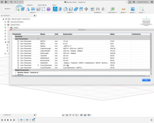
So the above measurements become my base numbers. Because I’m using Fusion 360 I would create a couple of parameters. So I created “Internal Length” and “Internal Width” with values of 600 and 300.
There are other base parameters as well. MDF12 and MDF6 refers to the dimensions of the wood I was using. I like to name these according to the type of wood. MDF refers to the fact I’m using MDF or Custom Board for this project and the 12 and 6 refer to the thickness.
This is where Fusion 360 gets cool and rules it over all other apps except for pen and paper. I needed a parameter to define the depth of the rabbet. That was this:
Rabbet = - MDF12 / 2
I created a negative value because a rabbet is a cut so… Already you can see why Fusion 360 is a great option for designing. This negative value creates a rabbet exactly half the thickness of the MDF I’m working with. Why not use -MDF6? Because if I change MDF12 to say MDF18 then the size of the rabbet would be out. So now I have all the information I need to set the dimensions of this project. This is where Fusion 360 and even pen and paper rule. Check out the parameters I set:
MDF12 = 12 MDF6 = 6 Rabbet = - MDF12 / 2 InternalLength = 600 InternalWidth = 300 CabinetLength = MDF12 + InternalLength + MDF12 CabinetWidth = InternalWidth + MDF12 SideLength = InternalWidth - Rabbet TopShelf = 40 MiddleShelf = 80 BottomShelf = 50 SideWidth = - Rabbet + TopShelf + MDF6 + MiddleShelf + MDF6 + BottomShelf - Rabbet CutoutDiameter = 20 CutoutPosition = CutoutDiameter + MDF12 ShelfLength = InternalLength - ( Rabbet * 2 ) ShelfWidth = SideLength
You might notice that a couple times I used “- Rabbet” in the calculations. The reason for that is that I needed positive values and a negative minus a negative equals a positive.
But as you can see these parameters feed off each other in some way. I could change MDF12 to “Ply18 = 18” and Fusion 360 would change that to Ply18 with a measurement of 18mm. The whole drawing changes with it.
The parametric approach of Fusion 360 works well for all forms of design. It allows you to ensure that what you are designing is going to be in proportion no matter what medium you use. If you’re using SketchUp then there’s no ability to store these calculations. You’d have to use a pen and paper or a spreadsheet to do the same thing. No matter what method you choose to design, I recommend this style of approach. It makes changing things down the line easier.
Fusion 360 vs SketchUp
The big question now is which method is better? Should I learn SketchUp or Fusion 360 or should I learn to do it on paper?
I rule out paper but that’s because it’s kind of expensive if you add it all up. It also requires more space than I actually have because of the need for a drawing desk. This section now becomes a duel between Fusion 360 and SketchUp.
SketchUp is a pretty great tool. To get the best out of this app if you’re a beginner then you need to checkout The SketchUp Essentials. I learned 3D design using this method and found it pretty cool only the more I used SketchUp the more I hated it. I found it’s facial editing to be a pain in the butt because everything was a separate face including the edges. This got frustrating when I thought I had grabbed an entire face only to have grabbed an edge. This made everything warped and twisted. I hammered the hell out of Command Z in SketchUp. Not only that but once you’ve made everything it can be difficult to change everything later on. It’s not undoable. It’s not easy and if you’ve not followed good standards then it can be a matter of starting all over again. The worst thing about SketchUp is that to use the free client you have two options. Either use the web client or use an old version of the desktop client. So you’ve either got to use unsupported software or have a constant connection to the internet. This can be annoying, although I must say our internet is pretty awesome so it’s not an issue for me.
This leads me to Fusion 360. Fusion 360 is very much a real-world editor. By this, I mean that instead of creating faces it creates bodies and you use those bodies desired. But it’s the parametric editing that makes Fusion 360 the best for woodworkers. Use the parameters I've listed above in Fusion 360 now if you want. It’s now a matter of creating components and sketches and you’ve got a model. This model will take me about 50 minutes to create from scratch and that’s including the rabbets and parts.
You don't have to be a pro user. Download Fusion 360. When asked for a licence, run through the questions to see if you’re eligible for the free licence. Make sure you say that you’re a hobbyist to get Fusion 360 for free. If you are going to make money from plans, etc. then you buy a proper licence because it’s only fair. Fusion 360 is pretty easy to learn but it will need you to rethink how you do things. Once you learn you’ll wonder why you did it any other way.
Conclusions
I’ve come a long way since I started woodworking and much of what I’ve built has been reverse engineered to suit my needs. Before Fusion 360 I worked off quick designs on paper but since then I design all my stuff in that now. I even have a plan for a helicopter that I designed from scratch. Fusion 360 makes this so easy.
I’ve described nothing that you can’t do in other media such as SketchUp, AutoCAD, or good old pen and paper. Whatever method you choose you need to understand if you are designing for an area, or to house something.
You should aim to start designing if you want to kick off your skills as a woodworker. Projects found on the internet are a great place to start. But there’s nothing quite like designing something yourself. Whether you use CAD or pen and paper do give it a go. Remember to research though especially if you are designing furniture. This is because you need to factor in forces acting on that furniture in order for it to be safe.
0 notes