#accelstepper
Explore tagged Tumblr posts
Visit Tumblr Blog
Explore Tumblr blogs with no restrictions, modern design and the best experience.
Last Seen Tumblr Blogs


Fun Fact
Tumblr has been banned in Indonesia for providing people with access to pornographic content.
Text
Pulley & Belt Transmission

Admittedly, building a robot arm joint transmission is way more difficult than I expected. But where's the fun in a simple project? In my last post, I explained why a geared transmission doesn't work. This week I'll try a new approach.
As hinted in my last post, I'll give a timing belt and pulley transmission a go. The added benefit of using transmission pulleys in stead of gears is that I'm able to 3D print them. Since the force will be distributed over 50% of the pulley teeth, 3D printed pulleys should be able to handle the necessary torque.
I printed a small prototype to see if 3D printed pulleys would work, and although GT2 pulleys are on the limit of what is printable with a 0.5mm nozzle, they work absolutely fine. Just make sure the belt tension is sufficient.

So after my prototype had proven the possibilities of 3D printed pulleys I started working on a full fledged transmission.
The small (bought) pulleys I use are 20 teeth, so by using 80 teeth large (3D printed) pulleys, there is a 1:4 speed reduction. Since I aim for a 1:16 speed reduction, I needed to put two 1:4 reductions in series.
The "packaging" of the transmission matches the 60mm diameter pipe I'll be using fo the robot arm body.

After a few hours ... days ... of Fusion 360, the render looked extremely promising!

Of course, I need to do some real world testing before I can say anything about the accuracy, speed and torque. So fire up the Lulzbot, feed it some FormFutura HDglass, and start the printing!
Since the Lulzbot Mini has a print bed of 150x150 mm, the joint is built up by three separate pieces. Not only does this allow me to overcome the size limit, but it also helps in preserving strength and print quality by alternating the print orientation.

The 3D-printed body is provided with ball bearings which accommodates the 5mm and 8mm shafts. As a shaft, I simply use some hex head bolts. Bolts aren't precisely sized, but are very convenient to attach to a 3D printed part. Together with the ball bearing, the bolts seem to do their job.

I initially expected that I needed to add belt tensioners, but by calculation the needed pulley distance, I was able to get a perfect belt tension.
In the photo below, the large pulley on the main shaft only has one set screw. It turns out this wasn't sufficient, so I ended up redesigning this pulley to accommodate two 3mm setscrews.

The main shaft (bolt) will be attached to the matching joint part. this part might eventually get a redesign, but for now it will be used to temporarily mount a piece of 60mm pipe.

To make the test setup look a bit more impressive, I sticked an old joint prototype in the end of the pipe (and used some black electrical tape to keep it in place).

So there you have it. The one axis prototype of my robot arm. I can't wait to give it a test spin! So without further ado, I present you the first results:
youtube
It works wonders! The accuracy is impressive, there is no backlash and the torque is much higher than I expected. As a matter of fact, I wasn't able to stall the motor. The first point of failure where the slipping setscrews of the pulley. I managed to solve this, by flattening the bolt on the position of the setscrews. I'll do some actual torque tests as soon as I've manages to mount the joint in a proper way (in stead of the electrical tape).
The video also shows the acceleration and deceleration of the joint. This is not due to a spin up or spin down of the motor, but programmatically generated by the AccelStepper motor library I use. This is fully configurable (as well as the maximum speed).
The next steps on the to-do lists are properly mounting the joint and designing some nice covers to hide the pulleys and belts. But more important: getting real time absolute position feedback by using an encoder. Stay tuned!
Let me know what you think about this design in the comments down below!
#robot#robotics#engeneering#3dprinting#3ddesign#fusion360#formfutura#hdglass#lulzbot#stepper#nema17#accelstepper#arduino#video#prototype#pulley#belt#gt2#transmission#joint
4 notes
·
View notes
Video
youtube
Mô tơ bước lớn
Cách sử dụng mô-đun trình điều khiển microstep và Arduino để điều khiển động cơ kích thước NEMA 23.
Bài viết có mã: https://dronebotworkshop.com/big-step...
Các bài viết và hướng dẫn khác: https://dronebotworkshop.com
Tham gia cuộc trò chuyện tr��n diễn đàn: https://forum.dronebotworkshop.com
Động cơ này là một con quái vật kích thước NEMA 23 có công suất lên đến 4,2 ampe trên mỗi cuộn dây, nhiều hơn những gì có thể điều khiển và H-Bridge đã sử dụng trước đó.
Để điều khiển động cơ này thì sẽ sử dụng mô-đun microstep, một thiết bị phổ biến có sẵn trên eBay, Amazon và tại cửa hàng cung cấp điện và điện tử tại địa phương của bạn. Mô-đun sử dụng là mô hình MA860H nhưng hệ thống dây điện và mã hóa sẽ hoạt động cho bất kỳ mô-đun nào trong số các mô-đun này.
Để chọn một mô-đun phù hợp với động cơ bước của bạn, bạn sẽ cần biết cách đọc và giải thích một số thông số kỹ thuật của động cơ bước, vì vậy ở đây sẽ trình bày về điều đó. Một thông số kỹ thuật đánh lừa nhiều người là xếp hạng điện áp, tôi sẽ giải thích lý do tại sao con số trong bảng thông số kỹ thuật có thể bị bỏ qua!
Tôi sẽ chỉ cho bạn cách kết nối mô-đun microstep với Arduino và cách viết mã cho nó, sử dụng một bản phác thảo đơn giản và cả thư viện AccelStepper.
0 notes
Text
Assignment 3 Iteration One
The first iteration of my code basically just runs the stepper motor (28BYJ-48) at a constant speed of 500 steps per second. The stepper motor is in half step mode, so one full revolution takes 4096 steps. So it takes about 8 seconds or so for the stepper motor to make a full revolution. I’m using the AccelStepper library by Mike McCauley, as it allows for easy control of the stepper motor as well as acceleration and deceleration. I’ve connected the stepper motor to a 9V battery as while the stepper motor can be directly powered from the Arduino 5V output, this can lead to the Arduino getting damaged if the stepper motor draws too much current. However, due to the ULN2003 driver board, this makes the process much easier, and lessens the amount of components that need to be used. Each stepper motor takes up 4 output pins, so with the 2 stepper motors I’ll be using, I’ll have 6 output pins for the rest of my components. I’ll have to look into how to fit everything in. In my next iteration I’ll be looking at how to move the stepper motor in different directions.
0 notes
Text
This light painting machine puts a new spin on the old geometric chuck
Light painting is a fun way to create digital images by using just a few points of light to “draw” across a camera with a long exposure time. This gives the illusion of a virtual streamer being dragged on the canvas and can produce amazing photos. Ted Kinsman wanted to build a light painting machine, which mimics the geometric chucks from the 1860s that used several spinning platters on a lathe that rotated at different speeds to carve ornate patterns into wood. His version has a series of three platters all stacked on top of each other and are driven by three stepper motors.
A single Arduino Uno runs the program for the geometric light painting machine, and it is responsible for controlling the stepper motors through its three attached TB6660 motor driver modules. The code works by first initializing each stepper as an AccelStepper object and then setting its max speed. The magic comes from this next part, and each motor gets assigned a constant speed value that determines what kind of pattern will be drawn. And finally, the motors are run at these speeds until the machine is stopped. The vast number of combinations from these variables means that even a small change to the motors’ speeds or where the LED is positioned on the top platter can generate wildly different results.
You can read more about Kinsman’s geometric light painting machine in his article on PetaPixel.
The post This light painting machine puts a new spin on the old geometric chuck appeared first on Arduino Blog.
This light painting machine puts a new spin on the old geometric chuck was originally published on PlanetArduino
0 notes
Text
I put the aquarium on the plinth and things are starting to become realized...

I put my first model in there as a placeholder.
then I spent the day pulling hair out over coding.
Thankfully I got the neopixels to work - they aren’t going to stop on a colour right now, I just need them to change colours for the time being, and I can adjust the coding later on perhaps.
So I hummed and hawed over the motor, I thought I had grasped Bobbi’s explanation of stepping forward, but I couldn’t get it to work.
I headed to the WIP lab, and Bobbi patiently tried to help me again. I got frustrated and started reading about the motor - a page I had read at least 10 times - and I found an example sketch that did something really similar to what I wanted the motor to do - and no delays used!
so I tested it.. and it worked... and then I combined it with the neopixel code.. and it worked!
#include <Adafruit_NeoPixel.h> #include <AccelStepper.h> #ifdef __AVR__ #include <avr/power.h> // Required for 16 MHz Adafruit Trinket #endif
// Which pin on the Arduino is connected to the NeoPixels? // On a Trinket or Gemma we suggest changing this to 1: #define LED_PIN 6
// How many NeoPixels are attached to the Arduino? #define LED_COUNT 8
// Define step constant #define FULLSTEP 4
// Declare our NeoPixel strip object: Adafruit_NeoPixel pixels(LED_COUNT, LED_PIN, NEO_GRB + NEO_KHZ800);
// Pins entered in sequence IN1-IN3-IN2-IN4 for proper step sequence AccelStepper myStepper(FULLSTEP, 9, 11, 10, 12);
//for timing of the neopixel of rainbow function (without delay) unsigned long previousMillis = 0; const long interval = 50; int color = 0;
void setup() { // put your setup code here, to run once:
// These lines are specifically to support the Adafruit Trinket 5V 16 MHz. // Any other board, you can remove this part (but no harm leaving it): #if defined(__AVR_ATtiny85__) && (F_CPU == 16000000) clock_prescale_set(clock_div_1); #endif // END of Trinket-specific code.
pixels.begin(); //initialise pixels pixels.setBrightness(50); //turn down the brightness so they dont burn your eyes pixels.show(); //show nothing
// set the maximum speed, acceleration factor, // initial speed and the target position myStepper.setMaxSpeed(2000.0); myStepper.setAcceleration(100.0); myStepper.setSpeed(1800); myStepper.moveTo(200);
}
void loop() { // put your main code here, to run repeatedly:
rainbow();
// Change direction once the motor reaches target position if (myStepper.distanceToGo() == 0) myStepper.moveTo(-myStepper.currentPosition());
// Move the motor one step myStepper.run();
}
void rainbow() { //function to get a rainbow pattern on the neopixels
unsigned long currentMillis = millis(); //record the current time
if (currentMillis - previousMillis >= interval) { previousMillis = currentMillis; pixels.setPixelColor(0, Wheel(color)); pixels.setPixelColor(1, Wheel(color)); pixels.setPixelColor(2, Wheel(color)); pixels.setPixelColor(3, Wheel(color)); pixels.setPixelColor(4, Wheel(color)); pixels.setPixelColor(5, Wheel(color)); pixels.setPixelColor(6, Wheel(color)); pixels.setPixelColor(7, Wheel(color)); color ++ ; if (color == 255) { color = 0; } pixels.show(); } }
uint32_t Wheel(byte WheelPos) { //function to get the colours for the rainbow WheelPos = 255 - WheelPos; if (WheelPos < 85) { return pixels.Color(255 - WheelPos * 3, 0, WheelPos * 3); } else if (WheelPos < 170) { WheelPos -= 85; return pixels.Color(0, WheelPos * 3, 255 - WheelPos * 3); } else { WheelPos -= 170; return pixels.Color(WheelPos * 3, 255 - WheelPos * 3, 0); } }
youtube
So the coding is done for now!
Then, I was talking to Bobbi about my shopping list for the final build, and she was reminded of a boost converter that could step the battery up to 5V, and it could be recharged.. and it could be WIRELESS so I don’t have to do leech surgery !
Thankfully I found out about this with an hour before Lee’s closed until Monday, so I ran and got the supplies and tested them out at home.

here you can see the transmitter and receiver

here you can see the led indicator that it is charging through the leech!
youtube
woot!
0 notes
Text
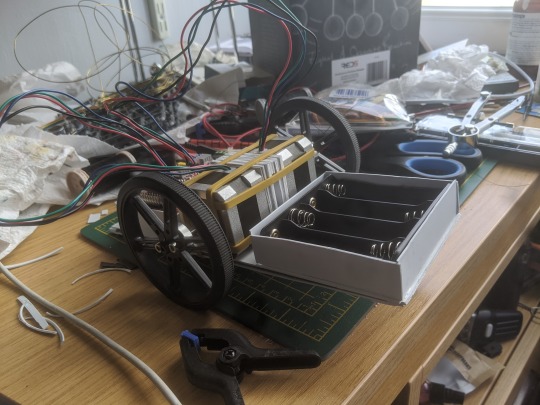
Floor Crawler
As part of the experiments portfolio assignment I will be documenting the progress of constructing and coding a floor crawler bot.
Equipment used:
1 x Arduino Leonardo
1 x CNC shield
2 x Two Phase Stepper motors (Jumper Cables)
2 x 8 cm Diameter wheels
1 x 3.7 V Series Battery Tray
4 x Samsung INR18650-25R Lithium Ion Batteries
1 x Ultrasonic Rangefinder HR-SR04 w/ jumper cables
2 x Sheets Midwest White Styrene .040 x 7.6″ x 11″
4 x Strips of Sprue sourced from Games Workshop sprues
10 x Mixed size clamps
1 x Revel Contact Cement
1 x Hobby Knife
1 x Pair of Scissors
Constructing the Crawler:
Part of the challenge with building the crawler was creating a chassis capable of bearing the weight of all the components. The biggest concern was the motors, as these weighed 250g (0.55lb) each. This meant that the chassis had to bear a weight in excess of 500g (1.10lb) to hold two motors, Arduino, shield, ping sensor, battery tray and batteries.
In addition to this, suitable materials for the chassis were fairly limited. This was because they had to be large enough to form the base and stiff or sturdy enough to bear the weight. This immediately ruled out materials like card as, whilst easy to acquire in large sections, they were far too flimsy to bear the weight. The only suitable materials available were styrene plasticard and model sprue.

However, like card they were too flexible for use so had to be stiffened through engineering tricks and simple reinforcement. The first attempt got off to a poor start, as the base was far too small to hold all of the components. With this initial set back in mind, I set about creating a new, much larger one with excess room for components to be added as necessary. In order to stiffen the base a method of diagonal strips of material was used. This involved placing two strips of sprue inside the base and a series of styrene strips placed on the bottom. This massively helped stiffen the base of the crawler allowing it to bear the weight of all components on the board, without flexing excessively.

For holding everything together I used Revel Contact adhesive as this would ensure a firm bond to hold the chassis together. To ensure a flat surface and to prevent air bubbles compromising the structure by forcing the styrene apart, I used small modelling clamps to hold components down whilst the glue cured.
The next step was to create housing for the individual components with the first being the battery tray. It was formed from four pieces of styrene attached to the base with a small hole added in front of the wires where they protrude from the battery tray. This would allow the battery tray to fit snugly into the housing without needing to flex the wires over the housing.
Next was the housing for the Arduino and shield which was formed the same way as the battery tray housing. However, this was slightly higher to account for added height of the shield, with a section cut out for the cable which connects the power cables to the Arduino and Shield.
To finish the base of the crawler I added two plastic bottle caps to each end of the base. This served two purposes; to prevent the crawler from grinding wither end of it’s chassis into the floor and the other being to reduce the extremes of highs and lows that would drastically throw the sensor off. The only complication with this was that the caps proved to be unaffected by the glue, this resulted in one incident where a cap popped clean off of the chassis.
The ping sensor was the final component to be attached, after connecting the jumper cables the last problem was to attach it to the chassis facing forwards. This was done by simply blue tacking the sensor to the front.
Motors and rubber bands:
With the chassis completed it was then that the real problem of creating the crawler raised it’s head. The attachment of motors to the chassis was the biggest problem as there was no concrete method. To ensure they were even and central, several layers of styrene squares were layered together to form a sort of bracing block that would be sandwiched in between the two motors to ensure enough clearance between the wheels and the chassis. The block also featured a gap between the two sides so as to allow the wiring to go through unobstructed.
The initial method, which was really more on paper than in practice, was building a cage of styrene around the motors and then boxing them in with strips of plasticard, like door bars to keep them in. After much discussion with other people, however, the idea was ultimately scrapped.
The second method was the use of brass wire bent to form braces that would hold the motors on the chassis. However, this method was also scrapped due to the difficulty in forming a perfect fit around the motors and the realisation of a better solution.

The third and final method was the use of rubber bands as I thankfully had a small bag full of them. This was to prove the simplest and most effective method of getting the motors fixed on the chassis.

Of Code and Complications:
After the success of getting motors onto the chassis, I then encountered the next big problem of this project, programming the Arduino. Because I have not had much experience with coding an Arduino, let alone coding stepper motors, tinkering with the code proved more problematic than expected.
The easiest parts were accessing the accelStepper Library which can be found in the Arduino coder and finding code for running the echo sensor as both were online and accessed from the Arduino Forums, courtesy of Isaac100 who wrote the base code for the ping sensor to work found at https://create.arduino.cc/projecthub/Isaac100/getting-started-with-the-hc-sr04-ultrasonic-sensor-036380.
Modifying the code for the motors and the ping sensor to work together proved to incredibly finicky, the code also proved to be frustratingly temperamental with the crawler often racing in random directions. This is aptly shown in the demonstration video as the crawler appears to take on a life of it’s own.
Video of it running:
youtube
Self reflection:
Things I did well:
Built a frame that was easy to construct for fairly cheap and could bear the weight of all components easily.
Was able to work around physical issues fairly well such as attaching the motors to the chassis and work with unusual solutions such as the use plastic bottle caps as skis.
Things I could improve:
Organise the wiring so that it is less messy and less likely to interfere with the wheels. This could be done with the use of rubber bands to tie the cables together as a substitute for actual cable ties.
Spend less time on the physical aspects of the crawler and instead focus more on the coding of the crawler. This would be possible with more practice at coding and gaining a better understanding of how the code interacts.
Conclusion:
Ultimately the idea itself was almost turned into reality but suffered at the last hurdle with a major roadblock which could have been overcome with enough time and experimentation to work out the kinks in the code.
Final Code:
#include <AccelStepper.h>
// ENABLE pin, inverted #define NOT_ENABLE_PIN 8
// The X Stepper pins #define STEPPER_X_DIR_PIN 5 #define STEPPER_X_STEP_PIN 2
// The Y stepper pins #define STEPPER_Y_DIR_PIN 6 #define STEPPER_Y_STEP_PIN 3
// Define some steppers and the pins the will use AccelStepper stepperX(AccelStepper::DRIVER, STEPPER_X_STEP_PIN, STEPPER_X_DIR_PIN); AccelStepper stepperY(AccelStepper::DRIVER, STEPPER_Y_STEP_PIN, STEPPER_Y_DIR_PIN);
const int trigPin = 12; const int echoPin = 13; float duration, distance;
void setup() { pinMode(trigPin, OUTPUT); pinMode(echoPin, INPUT); Serial.begin(9600);
// Enable drivers pinMode(NOT_ENABLE_PIN, OUTPUT); digitalWrite(NOT_ENABLE_PIN, LOW);
stepperX.setMaxSpeed(800.0); stepperX.setAcceleration(400.0); stepperX.moveTo(200);
stepperY.setMaxSpeed(800.0); stepperY.setAcceleration(400.0); stepperY.moveTo(200);
}
void loop() { int stepsToObs; digitalWrite(trigPin, LOW); delayMicroseconds(2); digitalWrite(trigPin, HIGH); delayMicroseconds(10); digitalWrite(trigPin, LOW);
duration = pulseIn(echoPin, HIGH);
distance = (duration*0.0343)/2; stepsToObs = distance/8; Serial.print("stepsToObs "); Serial.println(stepsToObs); Serial.print("Distance: "); Serial.println(distance); Serial.print(" X "); Serial.println(stepperX.distanceToGo()); Serial.print(" Y "); Serial.println(stepperY.distanceToGo());
// Change direction at the limits if (stepperX.distanceToGo() == 0 ){ if(stepperX.currentPosition() > 0){ //stepperX.moveTo(-stepperX.currentPosition()+stepsToObs/2); stepperX.moveTo(-200+stepsToObs/2); }else{ stepperX.moveTo(200); } } if (stepperY.distanceToGo() == 0){ if(stepperY.currentPosition() > 0){ //stepperY.moveTo(-stepperY.currentPosition()+stepsToObs/2); stepperY.moveTo(-200+stepsToObs/2); }else{ stepperY.moveTo(200); } }
while (stepperX.distanceToGo() != 0 && stepperY.distanceToGo() != 0){ stepperX.run(); stepperY.run(); } }
Bibliography:
Arduino (2020) Arduino Available at: https://create.arduino.cc/projecthub/Isaac100/getting-started-with-the-hc-sr04-ultrasonic-sensor-036380 (Accessed: 20th May 2020)
Arduino (2020) Info Protoneer Available at: https://create.arduino.cc/projecthub/Isaac100/getting-started-with-the-hc-sr04-ultrasonic-sensor-036380 (Accessed: 18th May 2020)
Arduino (2020) Arduino Available at: https://www.arduino.cc/en/tutorial/stepperSpeedControl (Accessed: 24th May 2020)
Arduino (2020) Arduino Available at: https://forum.arduino.cc/index.php?topic=563007.0 (Accessed: 28th May 2020)
0 notes
Photo


Screenshot of Code Iteration 3: Change to Stepper Motor library
Major change to this code was the shift from using the “AccelStepper” library to the standard “Stepper” library.
Minor changes, restructuring.
***NOTE: while this is is technically the fourth iteration of code, I counted it as the third because the changes were almost insignificant from 1.1 to 1.2, so I jumped in posting from 1.1 to 1.3.
0 notes
Video
tumblr
Bubbles machine prototype. 28byj-48 stepper with Arduino driven by AccelStepper.
Default Arduino Stepper library did not work correctly...
0 notes
Video
tumblr


Stepper Motor
Description of Project
The aim of this project is to create Stepper motor turning into same direction to complete at least one of the process of making voice control car. To be able to voice car you will need to have number of step that you should take. These are, collecting all the component you need for this project, having done with stepper motor, platting the car, adding Bluetooth onto it and prepare codes for this project to make it work correctly. So, in this stage I will be showing how stepper motor work without the wheels on it. In the further developments I will be adding all other steps for you to understanding.
Codes
#include <AccelStepper.h>
#include <SoftwareSerial.h>
String voice;
SoftwareSerial BTserial(2, 3); // RX | TX
// Define some steppers and the pins the will use
AccelStepper stepper1(AccelStepper::DRIVER, 2, 5); // Defaults to AccelStepper::FULL4WIRE (4 pins) on 2, 3, 4, 5
AccelStepper stepper2(AccelStepper::DRIVER, 3, 6);
int enablePin = 8;
char c = ' ';
void setup()
{
Serial.begin(9600);
Serial.println("Arduino is ready");
// HC-05 default serial speed for communication mode is 9600
BTserial.begin(9600);
Serial.println("BTserial started at 9600");
stepper1.setMaxSpeed(1000.0);
stepper1.setAcceleration(1000.0);
stepper1.moveTo(400);
stepper2.setMaxSpeed(1000.0);
stepper2.setAcceleration(1000.0);
stepper2.moveTo(-400);
pinMode (enablePin, OUTPUT);
}
void loop()
{
// Keep reading from HC-05 and send to Arduino Serial Monitor
if (BTserial.available())
{
c = BTserial.read();
Serial.write(c);
}
// Keep reading from Arduino Serial Monitor and send to HC-05
if (Serial.available())
{
c = Serial.read();
// Copy the serial data back to to the serial monitor.
// This makes it easy to follow the commands and replies
Serial.write(c);
BTserial.write(c);
}
// Change direction at the limits
if (stepper1.distanceToGo() == 0){
stepper1.moveTo(-stepper1.currentPosition());
}
if (stepper2.distanceToGo() == 0){
stepper2.moveTo(-stepper2.currentPosition());
}
stepper1.run();
stepper2.run();
}
Components
· Arduino optional board
· CNC SHIELD
· Stepper Motor M2
· Motor connection driver drv8825
· Wires
Improvements
This project has significant amount of capacity for improvements. For instance, you can make small cars or even voice control car once you add the rest of the plan of how you want to make.
Multi Stepper Motors (2011) https://forum.arduino.cc/index.php?topic=71978.0
Accessed on 02/05/18
0 notes
Video
tumblr
Day05_HW_ARDUINO_StepperMotor
The step motor stopped right after I tried out these two conditions twice, not responding to anything even if I restarted Arduino. I might have accidentally broke it. :(
---
#include <AccelStepper.h> #define HALFSTEP 8 #define FULLSTEP 4
// You need the AccelStepper library for this sketch to run. You can get it from here: http://aka.ms/AccelStepper
// The AccelStepper constructor expects the "pins" specified to be the ends of each coil respectively. // First the ends of the Blue/Yellow coil, then the ends of the Pink/Orange coil (Blue,Yellow,Pink,Orange)
// However, 28BYJ connector, ULN2003 board, and our current configuration is that pins are arranged in the proper FIRING order, // Blue, Pink, Yellow, Orange.
// No biggie, that just means that we need to pay attention to what pins on our Arduino, // map to which ends of the coils, and pass the pin numbers in in the proper sequence.
// To help with that, I will specify my pin variables based on their color.
#define blue 2 #define pink 3 #define yellow 4 #define orange 5
//Keeps track of the current direction //Relative to the face of the motor. //Clockwise (true) or Counterclockwise(false) //We'll default to clockwise bool clockwise = true;
// How many steps to go before reversing // int targetPosition = 2048; //2049 steps per rotation when wave or full stepping int targetPosition = 4096; //4096 steps per rotation when half stepping
// Initialize with pin sequence IN1-IN3-IN2-IN4 for using the AccelStepper with 28BYJ-48 // Notice, I'm passing them as Blue, Yellow, Pink, Orange (coil ends order) not // Blue, Pink, Yellow, Orange (firing order). AccelStepper stepper1(HALFSTEP, blue, yellow, pink, orange);
int switchPin = 9; int value; int buzzPin = 8;
void setup() {
pinMode(switchPin, INPUT); pinMode(buzzPin, OUTPUT);
//Set the initial speed (read the AccelStepper docs on what "speed" means stepper1.setSpeed(100.0); //Tell it how fast to accelerate stepper1.setAcceleration(50.0); //Set a maximum speed it should exceed stepper1.setMaxSpeed(4000.0); //Tell it to move to the target position stepper1.moveTo(targetPosition);
}
void loop() { stepper1.run(); value = digitalRead(switchPin);
if(value == 0){ stepper1.setSpeed(50.0); digitalWrite(buzzPin, HIGH); tone(buzzPin, 1000, 25); stepperDistanceCheck(); stepper1.run(); } if(value == 1){ stepper1.setSpeed(500.0); stepperDistanceCheck(); stepper1.run(); }
stepperDistanceCheck(); //If the stepper still needs to move (distanceToGo() != 0) //continue to advance (step) the motor stepper1.run();
}
void stepperDistanceCheck(){ //Check to see if the stepper has reached the target: if(stepper1.distanceToGo() == 0){ if(clockwise == true){ clockwise = false; //Go counterclockwise now stepper1.moveTo(0); //Go back to the "home" (original) position } else { clockwise = true; //Go clockwise now stepper1.moveTo(targetPosition); //Go to the target position } }
}
0 notes