#and now I need to buy and program an ESP32
Explore tagged Tumblr posts
Visit Tumblr Blog
Explore Tumblr blogs with no restrictions, modern design and the best experience.
Last Seen Tumblr Blogs


Fun Fact
The Tumblr office adopted Tommy, an 11-year-old Pomeranian.
Text
just placed an order with jlcpcb for my first every custom-make circuitboard
fingers crossed I didn't screw anything up, because that's over 150 components I'll be soldering to it
1 note
·
View note
Text
met with the interim therapist yesterday
she now agrees that i have made a good faith effort with the new p.a. and that it is reasonable to try to find someone else
she also put our work on hold indefinitely
next week i need to do something but i am not sure what or how
--
[not sure if this should have a trigger warning, but my enthusiasm for certain kinds of technology is only loosely moderated]
i ordered an open source watch
it is on the proverbial slow boat from china
i tend to burn through watches quickly
so it makes sense to get a somewhat modular one that i can maintain myself (that is my lame excuse to buy a new toy)
it will also be my first experience with e-ink
it is based on an sbc (single board computer) that i have used before, so i can go into the open source code to add my own mods (the board, esp32, can be be programmed to be a controller board for a printer or other cnc machine) (speaking of printers, i need to print a case for the watch) (later, if the need is great, i can mill a case from an aluminum blank)
the watch has wifi, so there is a lot i can do with it
it is a new toy that should give us plenty of new puzzles to be solved
3 notes
·
View notes
Text
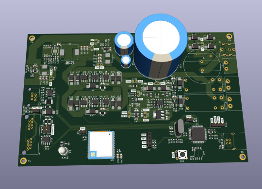
Let me introduce my current main WIP. It's not fandom related, it's for my model railroad, and it's not yet finished.
This is a rendering of a circuit board that I'm designing at the moment. It will be a DCC command station. My model railroad is run digitally, which means the tracks carry digital signals that tell each locomotive and switch individually how to run, which lights to turn and so on. The command station is the device that generates that. I have a number of different layouts, one of which has a good command station, one of which has a crappy old one, and the final one isn't even digital yet. So this will be the one that solves all issues for me, hopefully.
The design above isn't finished yet, and even the parts that are are not yet fully representative. The different capacitors are just there as options; some screen print overlaps; and some components (in particular all plugs and the relays that control the programming track) don't have 3D models so they don't show up.
Planned features:
Four layer board
10-25 V DC output, software controllable
Up to 5A output power, limited mainly by the main switching regulator.
Input 15-25V either AC or DC with polarity protection, selectable with some solder bridges (not yet in there). Optionally you can also bypass the main power regulator with another solder bridge (that I haven't added yet); useful in case you use e.g. a laptop power supply with a switchable voltage and don't need any regulation after that.
Railcom support
USB connection; not yet sure what for, but the main chip I'm using has USB support and I have some spare USB connectors here, so in it goes.
Speaking: The chip is an STM32L433RCT6P, chosen because I found it in stock at an electronics distributor. 64 kB RAM, 256 kB EEPROM, with support for an additional up to 256 MB externally (there's a spot for that on the board) and lots of fun extras that I don't technically need. It has an FPU! I don't need an FPU, but I will definitely do some floating point math computation on it just for fun.
Main external connection is WLAN using an ESP32 WROOM U module. I haven't decided on the housing, but I may go for extruded aluminum, so it's the U version that allows and requires an external antenna
It supports XBUS/XpressNet connections for old throttles from Lenz and Roco that I should probably throw away, but I paid good money for them, dang it.
It supports CAN for LCC / OpenLCB. I may not populate this part on all boards that I'm building, because I haven't actually decided whether I am interested. But the chip has CAN functionality built in, so why not.
There's an I2C connection to connect a cheap tiny OLED display for status messages.
Test points for all important signals (in particular the different internal voltage levels; yes, there is 3.3V, A3.3V and -3.3V and I need all of them).
Stuff still to add:
I will add pin headers (or space for pin headers anyway) for all the remaining pins on the STM32, and perhaps some on the ESP32, for future expansions.
Status LED and stop/go button on the front
Wire it all up, maybe move some stuff (mostly the STM32 around), which will cause all sorts of fun new routing issues.
Adjustments to make the jacks line up with the front panel once I've decided on a housing.
Features I'm not considering adding:
s88. I vaguely know what it is but I don't have any devices like that, and if that ever changed I could probably build (or perhaps buy) a converter that connects them via CAN.
Other buses like LocoNet.
Ethernet. I don't need it and it's actually more expensive than WLAN in this day and age.
In terms of software, I'm planning to use DCC-Ex on it. The whole project actually started out as a DCC-Ex shield, but once I realised that this wouldn't fit, I decided to make it standalone. Now, DCC-Ex is designed for Arduino, not STM32, and it doesn't support XpressNet, nor OpenLCB, nor Railcom, and their Wifi protocol is pretty weird and annoying which will be an issue (I'm planning to write my own control app for iPhone for it), so I'll probably change that or just replace it with the z21 one… so really, the software will not look a lot like DCC-Ex once I'm done with it.
Will this all work? I have honestly no idea. I mean, I'm fairly confident, I'd have given up on this long ago otherwise, but I have no guarantees either way until I've spent a lot of money on components and circuit boards and start soldering. Turns out doing it this way is not really cheaper than just buying a half-way decent one. That's what makes it exciting, though!
If it does work, obviously this will be released as open source. But it's still going to be a few days (more realistically weeks) before it's even ready to order the parts, and then a lot of soldering (current BOM stands at 194 actual components), and then a lot of software development before it's ready for that.
5 notes
·
View notes
Text
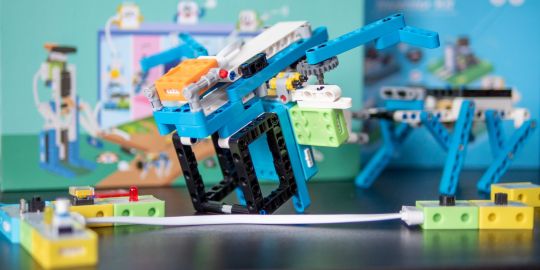
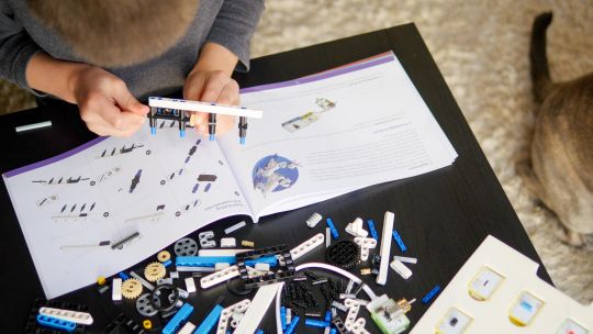
Elecrow Crowbits: The Ultimate LEGO-Compatible STEM Learning System That Grows With Your Child
Elecrow Crowbits
9.00 / 10
Read Reviews
Read More Reviews
Read More Reviews
Read More Reviews
Read More Reviews
Read More Reviews
Read More Reviews
Read More Reviews
Read More Reviews
Read More Reviews
Read More Reviews
Read More Reviews
Read More Reviews
Read More Reviews
Read More Reviews
Read More Reviews
Read More Reviews
Read More Reviews

Shop Now
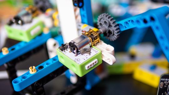
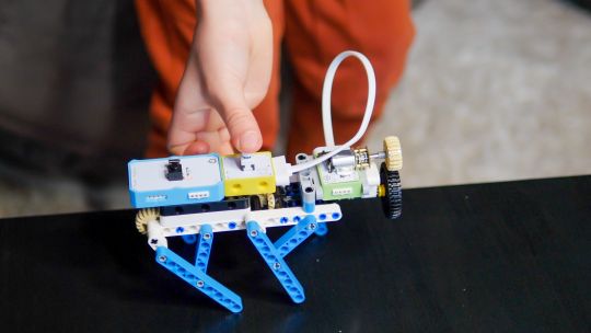
Brick builds, combined with magnetic electronics blocks, and programmable micro-controllers. Does it get any better than this? I think my long search for the perfect STEM learning kit is complete. If you have young children just coming up to the right age for it, the Crowbits system can accompany them throughout their primary education and beyond.
Key Features
Magnetic blocks build circuits
Kits to suit various levels
Specifications
Brand: Elecrow
Development Platform: Scratch and MicroPython
Pros
LEGO-compatible to customize your builds
Full range of components planned
Level up with your child with more complex projects and programmable microcontroller
Familiar Scratch-based programming software
Cons
It's a Kickstarter
Instructions need work expanding on the principles and explanations
Buy This Product
Elecrow Crowbits other
Shop
// Bottom var galleryThumbs1 = new Swiper('.gallery-thumbs-1', { spaceBetween: 10, slidesPerView: 10, freeMode: true, watchSlidesVisibility: true, watchSlidesProgress: true, centerInsufficientSlides: true, allowTouchMove: false, preventClicks: false, breakpoints: { 1024: { slidesPerView: 6, } }, }); // Top var galleryTop1 = new Swiper('.gallery-top-1', { spaceBetween: 10, allowTouchMove: false, loop: true, preventClicks: false, breakpoints: { 1024: { allowTouchMove: true, } }, navigation: { nextEl: '.swiper-button-next', prevEl: '.swiper-button-prev', }, thumbs: { swiper: galleryThumbs1 } });
Take a moment to imagine the perfect electronics and engineering learning kit. It would be so simple even a child could use it: magnetic blocks, perhaps? Modular, so you could swap bits in and out to modify projects. It would scale up, so you could start with simple circuits and move on to programmable hardware, catering to all levels of the curriculum. Lastly, I'd throw in LEGO-compatible, because LEGO bricks are the best tool for creativity and engineering ever made.
That's exactly everything the Elecrow Crowbits system is, and it's crowdfunding now.
youtube
Disclaimer: This is a Kickstarter
Four of the five available Crowbits kits were sent to us for evaluation during the Kickstarter, however, they are still very much in the prototype stage, and we've evaluated them on that basis. Some bits were missing, some were non-functional, and the software is still a work-in-progress. This is to be expected at this stage, but the core system is solid.
Also, the usual Kickstarter caveat applies: your money is at risk, and there's no legal obligation with any crowdfunding campaign to actually deliver a product. That said, this isn't Elecrow's first campaign (the CrowPi 1 and CrowPi 2 were a huge success). It's a well-established company with a reputation to maintain and a good track record, so we think the risk is minimal.
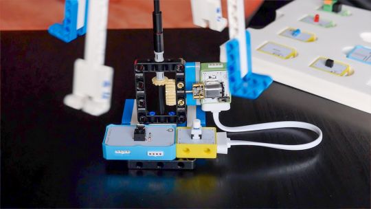
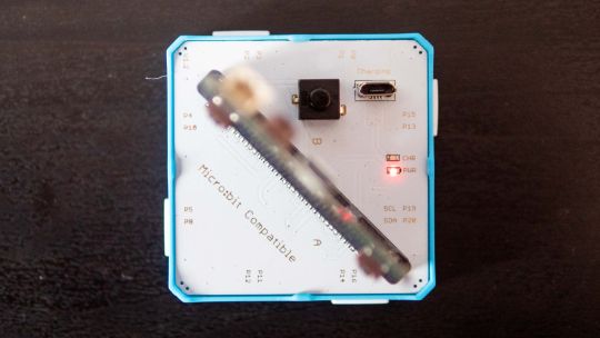
What Are Crowbits?
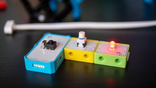
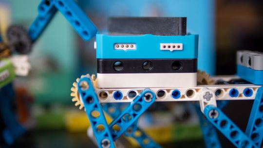
Crowbits modules are magnetic electronics blocks with LEGO-compatible pin holes on the side and stud holes underneath. The 4-pin pogo connections are either male or female, and have a small protrusion on the bottom to prevent wiring them the wrong way around.
Extension cables enable you to place a module elsewhere, and these too feature the same magnetic connection and can't be plugged in the wrong way. The whole system operates on a safe, low voltage, and with rechargeable battery blocks that charge over micro-USB.
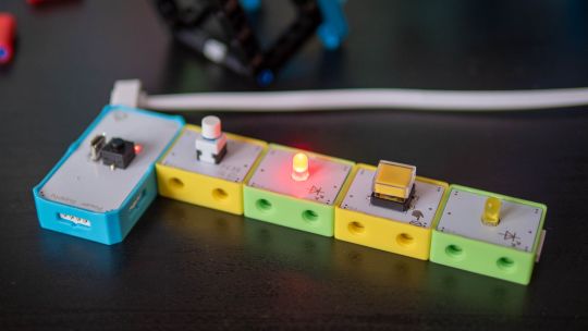
Each Microbits module is color-coded for ease of understanding:
Blue modules are power and logic. In the basic sets, these are simple battery modules that don't require programming. In more advanced sets, these are programmable microcontrollers with pin numbers on the connections for addressing modules directly.
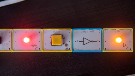
Yellow modules are inputs: buttons, basics sensors and such.
Green modules are outputs: LEDs, motors, buzzers, relays.
Orange modules are special and require serial communication lines to the programmable hub. These include things like color sensors, joysticks, or 2G communications hub.
A large range of Crowbits modules are planned, though these will be available separately at a later date. For now, you can only purchase the full Crowbits kits with their included module selections.
No Programming Required!
Since the first two Crowbit kits require no programming, how does that work? Simple, as long as you follow some basic rules:
Yellow input modules must be placed on the left of green output modules (when viewed with the module name being on the top, and symbol in the bottom right).
One input module can control a chain of output modules.
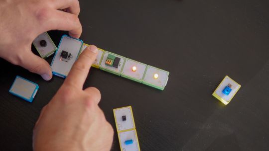
A new input-output chain will be created if you add another input module to the right.
Blue battery modules can go anywhere in the circuit, and their orientation doesn't matter as long as the pins are compatible.
With this, kids can create basic circuits. For more complex circuits (that still don't need programming), a series of bitwise logic operator modules are planned. A "NOT" logic gate is included in the Hello kit, and more will be available later.
This enables you to reverse an input, such that a button that would normally turn on an LED, would now function as a button to turn the LED off.
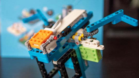
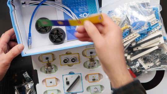
Crowbits Kits
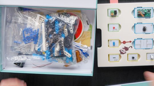
The Crowbits Kits are divided into five stages of increasing complexity, but all share a common system and are compatible with each other. Some modules are duplicated between kits. Let's take a look at the contents and direction of each kit.
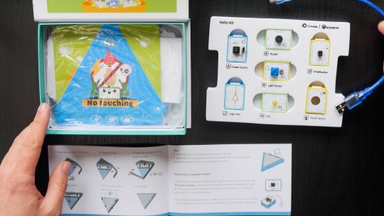
Hello Kit
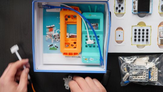
The most basic of kits is also the cheapest, available for $30. It includes seven modules, one of which is a small battery module. Five project builds are included along with pre-cut cardboard parts to stick together. No programming is required, and the Hello kit is suitable for ages 5-6.
Explorer Kit
The Explorer Kit continues the no-programming theme, but adds movement through the use of a motor module and pack of technic pieces for some basic engineering. A total of eight modules are included, one of which is a medium-sized battery pack. The build guide contains a mix of brick-based and cardboard projects. With a little adult supervision on the trickier mechanical elements, 7-8-year-olds should be able to handle this kit. The Kickstarter price is $80, rising to $130 RRP.
Inventor Kit
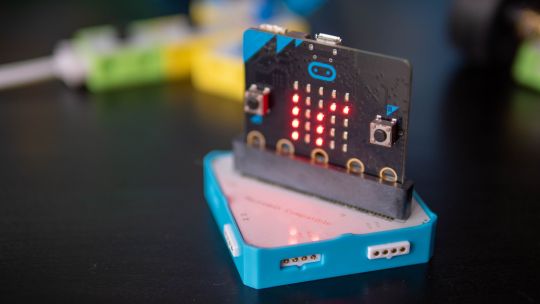
The Inventor Kit is a big step up that introduces programming concepts and more complex mechanical engineering. The main module of this kit requires a BBC Micro:bit (v1) to function. This is not included, though it may be available as an add-on if you don't already own one.
For those not familiar, the BBC Micro:bit is an all-in-one programmable microcontroller specifically designed for use in the school curriculum. It's widely used in UK schools, and gaining ground in the US.
Related: 10 Beginner Projects for the BBC Micro:bit
Ten modules are included as well as a large pack of technic bricks, suitable for building projects such as an obstacle avoidance car or color-sorting robot.
Given the use of BBC Micro:bit and Scratch programming in schools from around age 8, this kit would be suitable for 8-12 year-olds. It's available during the Kickstarter for $90, RRP $130.
Creator Kit
This was not yet ready for review at the time of writing, but the core of the Creator kit is an Arduino-based board, and includes 11 modules more suited to smart home projects and more complex interaction programming, along with a small selection of technic blocks. There are no movement motors. The Creator kit is available for $100 now, or RRP $150 later.
Master Kit
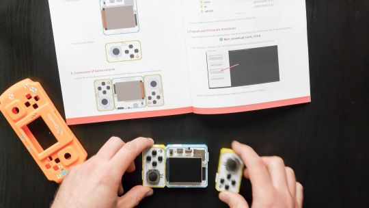
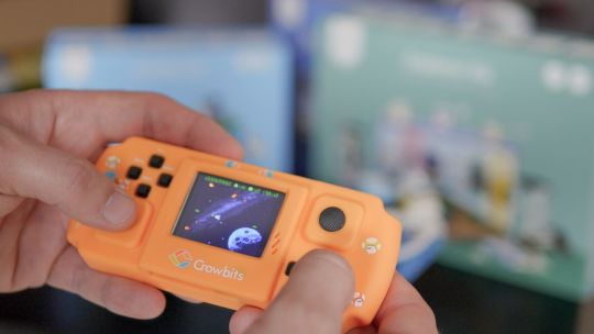
The most advanced kit in the range, the Master Kit uses an ESP32-based board at its core, featuring a TFT color screen. Also in the kit are some joystick modules, a small keyboard, laser ranging sensor, and 2G connection.
The Master Kit has a small number of technic bricks, and as well two silicone cases for a working phone, and a retro game console. It's designed to show the modules coming together to create a finished product. However, programming the firmware is quite complex, so I'd rate this kit as suitable for 14 and up. The early pricing is $100 for the Master kit, rising to $150 RRP.
LEGO-Compatible, not Actual LEGO
I should note that the Crowbits kits are not an officially endorsed nor licensed LEGO group product, and do not contain actual LEGO bricks. Instead, the LEGO-compatible technical bricks carry the brand name "CaDA", which I've not come across before.
That said, the bricks are well made and connect simply and securely, which is always a worry with off-brand construction bricks. For context, you can buy a set of at least 500 CaDA technic bricks on AliExpress for under $30.
You can of course decorate the builds with your own real LEGO, should you wish.
As a nerdy side-note, be warned that the instruction for the brick builds are read left-to-right, rather than top-to-bottom. If you're a LEGO family, this is mildly infuriating and means your child might skip steps!
Programming with LetsCode
Programming your Crowbits kits is done using Elecrow's new LetsCode (currently only for Windows, but support is promised for Mac OS and Raspberry Pi later).
LetsCode is a customized version of Microsoft MakeCode, which is itself based on the graphical block programming language, Scratch 3.0. As such, it'll be immediately familiar to anyone with experience of Scratch programming. It's widely used for introductory programming classes all over the world, and includes graphics blocks for all common concepts like loops, branching, and functions.
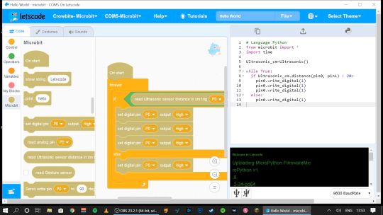
Pin numbers are printed directly on the blue modules, so it's easy to see which component is attached where.
If you outgrow graphical programming, you will also be able to program in MicroPython or Java, though this was not supported at the time of testing.
Should You Back the Elecrow Crowbits?
The Crowbits magnetic circuit system is easy to use and scales well for different ages and user levels. You can start with simple circuits, and move on to programmable logic controllers, and still reuse all the bits. It's a system that will grow with your child throughout their learning journey from age 6 to 14. Very few educational toys can make that sort of claim.
If you want your child to have a competitive edge in the programming, electronics, and engineering aspect of the STEM curriculum, then supplementing schoolwork is a great idea.
Even though many schools have now returned, it's possible you've opted to fully homeschool or just want to supplement their existing classwork. Over the next few years, schools will inevitably be different. There'll be a lot less practical work going on because of the aspect of touching shared equipment, so having this sort of kit available at home with software that's familiar will be of great benefit.
That said, the Crowbits kits vary greatly. If you're a completionist, you can grab a bargain bundle during the Kickstarter of every Crowbits kit available, for a cool $400 (rising to $600 RRP after the campaign).
But I think the best value comes from the Explorer, Inventor, and Master Kit bundle for $270. This includes a ton of mechanical bricks and plenty of movement modules. The BBC Micro:bit compatibility ties in perfectly to the existing curriculum (in the UK, anyway), while the ESP32 board is a good step up once they're old enough.
If you're only going to purchase one kit, I'd recommend skipping the Hello kit and going straight to Explorer or Inventor, depending on whether you want programming introduced yet. The cardboard projects in the Hello kit just felt a little too contrived and didn't engage my 6-year-old son in the same way LEGO does.
While the mechanical elements of the Explorer kit may need a little adult supervision, he was quite capable of the bulk of construction and able to use the LetsCode software thanks to previous experience with Scratch.
On the other end of the scale, I wasn't overly impressed with the Master kit either. The game console project, while it produces a cool end product, consists of simply the main board and two joystick modules on the side.
There is no construction, and the hardest part is loading on firmware, which tedious at best. The phone project is also impressive but limited to a 2G network, many of which will be disabled by the time the Crowbit kits ship. The ESP32 mainboard is technically impressive, but once your teenage child is ready to program this thing, the magnetic block system may not be appropriate anymore. It's a good addition to your collection if you're purchasing the earlier sets too, but I wouldn't purchase it alone.
Overall though, I think my long search for the perfect STEM learning kit is complete. If you have young children just coming up to the right age for it, the Crowbits system can accompany them throughout their primary education and beyond. And when they're done with it in a decade, we'll probably all be learning in VR anyway.
Alternatives to Crowbits
Crowbits isn't the only STEM kit around. The closest competitor is the littleBits STEAM kit, which retails at around $400, doesn't include any technic bricks, and has a limited selection of magnetic modules. It's more closely aligned to the US curriculum though with more extensive teaching materials, and already in use in many schools.
The LEGO groups' own Robot Inventor MindStorms kit is also worth considering, retailing at $350. It's focused more on robotics than basic electronics, and isn't suited to younger children, but the software is also based on Scratch. It would make a great step once your child reaches 14, and has outgrown the magnetic Crowbits system.
Elecrow Crowbits: The Ultimate LEGO-Compatible STEM Learning System That Grows With Your Child published first on http://droneseco.tumblr.com/
2 notes
·
View notes
Text
Will guide you to how to use a Wappsto IoT Cloud and to build your first project with Wappsto. Things used in this project Hardware componentsM5Stack M5StickC ESP32-PICO Mini IoT Development Board×1Arduino 101×1Software apps and online servicesArduino IDEwappsto Story Introduction: Here are some information about Wappsto, this information was taken from (https://wappsto.seluxit.com/about/) What is Wappsto? Wappsto is a web app store where you can share and, in the future, even sell your data and buy my data. But why would I want to buy and sell data? Data is the key to enriching my personal smart life. If, for example, my neighbor already has a weather station, I can save myself the trouble and buy his data. Okay, so why would I want my neighbor’s data? For example, with weather data, I could better control my floor heating. But how do I put the data to use? Wappsto! Wappsto is the AppStore that Steve Jobs might have dreamt of as a web app store. No SDK, just web standards. Wappsto where data exchange between you and me is improving our smart life. It is a sophisticated way to get your smart things and services to work together. Inspired by the AppStore, Wappsto is a web app store where you can find web apps to automate the stuff in your life. We call them ‘wapps’. Wappsto is also a web-based tool to create and run wapps. Wappsto brings together the capabilities of talented developers with the highly personalized needs of individual end-users. Because developers create programs with javascript, they have powerful flexibility, enabling end-users to tackle even the most challenging automation tasks with ease. Wappsto’s Mission We created Wappsto in response to recurring high-level challenges that we were facing when developing solutions for our customers within the Internet of Things (IoT). Our customers wanted to automate the interaction of their devices, but their customers also wanted to include third-party things and services in their automation. The desired automation was often complex, but they wanted flexible configurations in a straightforward user interface. We realized that there is no one-size-fits-all solution for these problems, so we developed a software framework to make creating these personalized solutions easier. Wappsto’s Vision Many hands make light work. We want to share the framework that we created with as many as possible because if we help individuals realize their own highly personalized ideas for combining things and services, there’s a lot of work to be done. But we have to work smart. We’ve taken our inspiration from the AppStore because a market is optimal to generate and capture value. All market participants stand to gain value. By employing a proven unified data model, Wappsto can represent any service or device of any producer. Wappsto is democratizing the process of integrating services and IoT devices. The more developers work together; the more powerful the platform will become. As it grows, more creative combinations are possible, and more end-users attract more developers in a positive cycle. So, I think now you guys have some understanding of Wappsto and it's services, now we are moving into a simple project that explains how we can use Wappsto into our IoT solutions?. Step-1 : Setting up Wappsto Cloud Service First you have to set up your Wappsto Cloud acount to use the Wappsto. Just type https://wappsto.com/ in your browser. Now we are in the Cloud Portal of Wappsto. Simply create a new account with your information or email ID, then click on login. After the login, you can see the home page of our dashboard. First we have to add our IoT devices to the Wappstro, and then we can visualize the data by charts and widgets. Wappstro uses certificates in order to communicate with cloud service, also you can use multiple mode of communication example (python, Arduino). We can generate the ce
rtificates by two modes, one is by using python script and another one is using the web certification method. In this demo, I'm going to show you the second way of generating the certification. Navigate to store tab in the Wappsto dashboard, and you can see the IoT certification manager, click on that and install that. Once you installed the certification, click on open, and it will direct to the certification page. Here you can see two types of certification, select the Arduino certification and just click on download. Once you downloaded the certification, click on the WappstoIoT for Arduino. It will redirect you to the GitHub page of Wappsto IoT, This repo includes the Arduino example source codes. Download this entire repo, we have to add this in our Arduino library. Step-2 : Setting up Arduino IDE Next, open up the Arduino IDE then goto Sketch→Include Library→Add Zip and select the downloaded the GitHub repo. Once you added the library, then open the File→example→Library Example. Select the Wappsto, and generic Temperature example. First, we have to add our certificate in this code for that save as this example in another name and location. Add the downloaded certification file into that project folder. Next, close your Arduino IDE and open up again. Now you can see the certification file added into the project. Now change the Wi-Fi SSID and Password in the project file. Then just compile the project. Once compilation successful, then upload to your ESP32 board. In this tutorial we are going to use M5Stick C, it's made upon esp32 core. Select correct board and com port, then click on upload. After upload, open up the serial monitor and see for the results, wait to complete the connection. Step-3 : Setting up Wappsto Cloud Dashboard Next move on to the Wappsto dashboard and navigate to the devices, there you can see our ESP32. Next, add widget, and select for the chart type. Then select the device data variable. Here is Temperature. Next move on to the chart customization and make as per your wish. Now you can see your data in the dashboard. Conclusion: In this tutorial I have shown how to use Wappsto and how to build your first project with Wappsto, Next will show how to build a GPS tracker based on ESP32 and Wappsto.
0 notes
Text
Picking apart the Joy-Con: Charging Joy-Con Grip and HID
Earlier this week I made a short post detailing some of my endeavors towards talking to Joy-Con and getting their firmware. However, as fun as it is to have my Joy-Con in pieces talking to my ESP32, I wanted a better way to conduct research with my Joy-Con.
To do this, I ended up buying a charging Joy-Con grip for about $30, a little bit costly but worthwhile if it happened to have the rail connectors I could tap into for UART (though I also had hoped when buying it, at least a little, that I could talk to the Joy-Con straight over USB) After receiving the device, I was surprised to find that it did not have a battery like I thought it would (not sure why I thought it had one), but additionally it also had USB descriptors! Looking at these descriptors, I was pleasantly surprised to see two interfaces with an input and output endpoint each, which slightly affirmed a small gamble I took hoping this would also function as a sort of HID<->UART bridge.
However, attempting to send UART packets to those endpoints yielded nothing at all. Just before I was about to take it apart and try more invasive measures, I was very pleasantly surprised to find that if I undocked or docked one of my Joy-Con, the device sent me a single packet: When it was undocked, 80 01 03, and when it was docked, a packet containing the Joy-Con MAC:

Getting this MAC would mean that the device was not only charging, but it also has to be talking UART to retrieve that MAC address. At the very least if it wasn't straight HID to UART, it was something very close.
After taking it apart, I was pleasantly surprised that had an STM32 identical to the extra STM32 chip found in the Pro Controller (which I don't have, but have seen pictures of):

Perhaps the most notable thing on this board though is the 5 throughholes on the bottom left. For a little bit of prior context, the Switch dock also has an STM32 of a slightly different variant, but in addition to this has a labeled 5-pin SWD interface on its board:

(Picture from iFixit Teardown of the Nintendo Switch)
As much as I'd like to just wire it up identically, I also didn't want to go carelessly hooking things up, because this device also happens to be 1.8v versus the dock's 3.3v (though the STM32 supports 3.3v just fine). After some probing, I found that the pinout was fairly similar but not quite identical, and with some soldering and wiring it up to an RPi (which had 3.3v logic) I had myself access to the device and debugging through OpenOCD:


After getting the firmware dumped over debug, I took it to a hex editor to poke around and found some interesting strings, notably the fact that the charging grip is able to boot into a Device Firmware Update mode. Because it’s 2017 and charging grips need that I guess:

Also as an interesting note, Kuina translates from Japanese to English as “Water Rail”, thought that was cute. The Switch already has a lot of ocean names in its software so having this added to the pile was neat.
I was also able to load it into IDA fairly painlessly (as opposed to the Joy-Con firmware which is still a big unknown for me). Finding the UART functions I wanted was as easily as finding the A1 A2 A3 A4 magic I had found before and then from there working backwards and around to find the general UART functions I would need to see. With some prodding and debug breakpoints, I also was able to find the portion of code which handles incoming HID packets, and with Hex-Rays its functionality becomes fairly clear:

From the top, it seems like there are some UART packets starting with 01 or 10 which can be sent straight over HID, but for the most part all of the custom HID work is done with the first byte as 80 followed by a second subcommand byte.
From an initial observation, I found that there were a few commands which let me just send UART straight for the most part (the main difference is that the header and checksum are handled by the grip). With some cobbled together initialization and commands, I succeeded in getting UART input packets sent... but they did not contain any button data at all, which was a bit strange:
youtube
With this portion of the firmware at least identified, I continued digging into some of the earlier 80 commands and after quite a bit of fiddling, I found a few things: First, the device initializes only both Joy-Con at once, if both are not initialized at the same time, the rest of the process fails or only works partially as seen above. This may be why this HID protocol isn't used by default with the Switch, since initialization actually takes a while and if the Joy-Con are already powered there's no real point in switching back and forth. Both Joy-Con being initialized at once may also mean that this firmware is simply half-baked and was abandoned at some point to a similar tune.
Additionally, I found that this device is indeed able to send any UART packets desired, though it does not have fine control over the header of those packets, so if you want to get a bit crazy you'll have to flash your own firmware to the grip. That being said, the initialization process I eventually found worked consistently was as follows (with each step being sent per-Joy-Con to both HID interfaces):
Send 80 01 to get the Joy-Con MAC and/or connection status. Send 80 02 to proceed with UART handshaking procedure. Send 80 03 to switch baudrate up from 1Mbit to 3Mbit. This seems to be required to get input delay down from 24ms-32ms to 8ms-16ms. Send 80 02 again to redo handshaking over UART so that the Joy-Con don't time out and disconnect after the baudrate change.
After initialization, any UART packets can be sent. The nice thing with the UART packets being crafted by the firmware is that it clarified the functionality of certain portions of the packets. For example, the general structure of an input request packet sent over HID vs UART is as follows:
80 92 00 01 00 00 00 00 1F 19 01 03 08 00 92 00 01 00 00 00 2D 1F
In these packets, the only real difference is the header for UART and the checksum byte before 1F. The 92 byte can either be 92 for post-handshaking commands or 91 for pre-handshake commands. This is followed by a u16 length for the payload of the packet, 1F. For HID, the checksum is handled by the firmware so the byte there can be left 00.
As another test, I also was able to dump my right Joy-Con firmware for the first time since I could send the same UART SPI read packets as before, and was surprised to see that it was actually significantly different. With the differences though, there were some things which caught my eye that I did not see from the first time. At 0x10000, there seemed to be an early version of the firmware, with "Joy-Con (L)", "Joy-Con (R)", "Pro Controller" and "Joy-Con Charging Grip" replaced with "NintendoGamepad01", "NintendoGamepad02", "NintendoGamepad03" and "NintendoGameadp", though it seems the Bluetooth names were still Joy-Con and Pro Controller elsewhere.

With all of that done, I've also ran a few test with Bluetooth and it seems that unfortunately the HID protocol isn't a perfect match between Bluetooth and the HID wired protocol. However, it may be close, and with that I have a few guesses:
For the Joy-Con, the SPI is likely not XIP, however I have a mild suspicion that the firmwares at 0x10000 and 0x28000 may have some kind of header for dynamic loading since RAM may be limited. In dekuNukem's SPI logic dumps, I found that larger portions of the SPI were accessed after docking than just powering on, which is why I initially thought it was just XIP, but the disassembly simply doesn't make sense.
Bluetooth may have a bit more security around it just because it's used a lot more, and for the average use case, Bluetooth is simply more desirable.
Also some notable things going forward:
Since the SPI flashes are dumpable over HID with a charging Joy-Con grip, checking whether Joy-Con updates have taken place will be fairly easy from now on.
As-is, the charging Joy-Con grip is more than enough to experiment with the UART protocol. Replaying commands between Joy-Con should be more than possible, and investigating the Pro Controller should also be doable.
For anyone interested in trying out communication with your own Joy-Con and charging grip, I have uploaded my HID test program in my HID-Joy-Con-Whispering repo.
#Joy-Con#HID#Joy-Con Charging Grip#It's2017AndChargingGripsHaveUpdatableFirmwares#Reverse Engineering#Firmware
2 notes
·
View notes
Text
ESP32 Web Server ft. Coronavirus
Hello, fellas!
After not post anything for 2 weeks, finally I’m back! How’s life? Stay safe everyone wherever you are. The world is in a bad condition where the coronavirus is spread all the entire world. I hope you in good condition and also the people you loved. Stay healthy everyone!
This global pandemic also affected to my campus life. The learning method is fully online or e-learning if I can say. The campus is locked down from last week until an unpredictable time. There’s no activity again on my campus, even if there’s an activity, it restricted to laboratory maintenance, and so on. So from last week, I’m staying at home and learn from home with a video conference. The lecturer of the subject shares a link of the conference so the student can join and study as usual. I can’t enjoy this because my laziness level is truly increasing with online learning. I’m lazy to wake up from my bed because I know I can learn from my bed (just by holding a laptop!!!), and I only take a shower when I remember ONLY (please don’t do this because we must maintain our body to keep them clean).
I think after this phase is over, it will be an interesting story to share with my children 10-20 years from now.
Okay, enough for chit-chat.
So this week project is making a web server with ESP32. Based on this link, I must test the ESP32 can control outputs using Arduino IDE programming. The web server must be accessed with any device (smartphones, laptops, etc).
The equipment required is:
ESP32
2x 5mm LED (but this time I only have one 5mm and one 3mm but I think it’s no necessary)
2x 330 ohm resistor
Breadboard
Jumper wires
Arduino IDE that installed on the laptop
USB Type-A Cable
Before I explain more, I want to disclaim something. All this time, I do my project with 2 of my friends for sharing the equipment so each of us can save our money more. But the minus is, we only have one for each equipment. We think it will no problem with it until we facing this quarantine because of the coronavirus. This condition makes who doesn’t bring the equipment can’t try and also we can’t do it together because we must keep distancing each other. Because the government and WHO said that we must keep distancing from other people at least 1 meters, I think it’s impossible to do this project together during this condition.
But last week I’m trying to buy the equipment that I need for this project and perhaps for the next project, but the new problem arises. Because of this coronavirus, regulation to reduce activity outside, I buy the equipment from e-commerce and will be delivered by courier. But during this condition, the courier on duty is reduced and the impact is the package arrived later than usual. Until today, I haven’t received the resistor yet so I can’t do the project by myself. Oh God, I only need a resistor!!!! The jumping wire has already arrived, and the other equipment also arrived but the only resistor didn't arrive. But okay, my friend who brings the equipment told me that she already did this project and she wants to share the experience, how ESP32 works and also the documentation. Thanks a lot for the internet that make impossible thing possible and bring the far closer hehe. Even I haven’t tried this project, I know a little bit about the project based on my friend explained. She explains from LINE chatting platform and also sends the documentations. But after my resistor arrived, I want to do this project asap and I’ll update it on my Tumblr so stay tune.
Okay back to the topic.
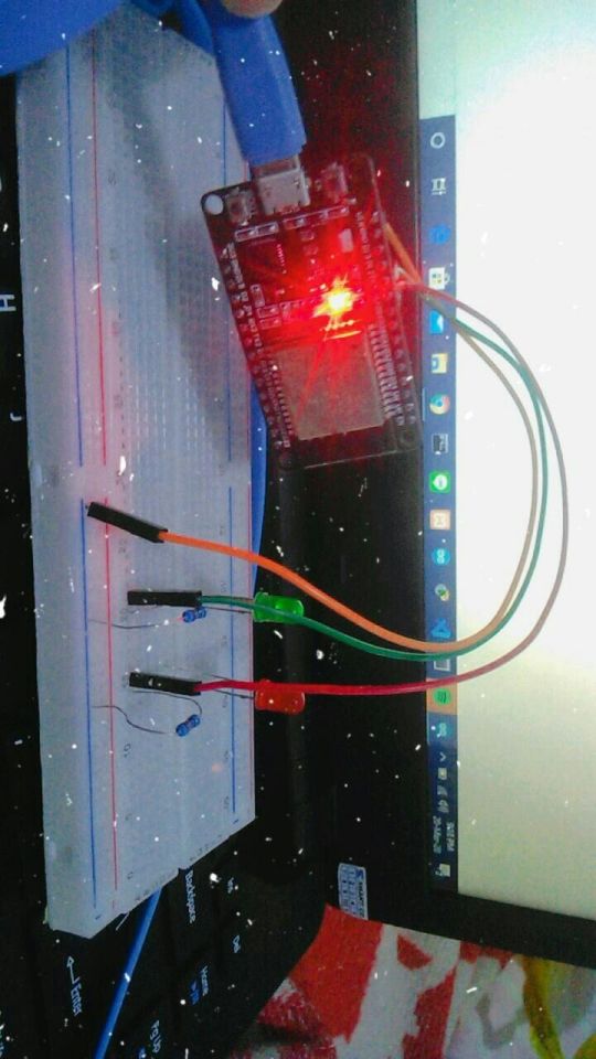
After collecting the equipment, we can start to build the circuit. Connect the LEDs to the ESP32 using breadboard and connect to GPIO port.
And this is the source code:
// Load Wi-Fi library #include <WiFi.h> // Replace with your network credentials const char* ssid = ""; const char* password = ""; // Set web server port number to 80 WiFiServer server(80); // Variable to store the HTTP request String header; // Auxiliar variables to store the current output state String output26State = "off"; String output27State = "off"; // Assign output variables to GPIO pins const int output26 = 26; const int output27 = 27; void setup() { Serial.begin(115200); // Initialize the output variables as outputs pinMode(output26, OUTPUT); pinMode(output27, OUTPUT); // Set outputs to LOW digitalWrite(output26, LOW); digitalWrite(output27, LOW); // Connect to Wi-Fi network with SSID and password Serial.print("Connecting to "); Serial.println(ssid); WiFi.begin(ssid, password); while (WiFi.status() != WL_CONNECTED) { delay(500); Serial.print("."); } // Print local IP address and start web server Serial.println(""); Serial.println("WiFi connected."); Serial.println("IP address: "); Serial.println(WiFi.localIP()); server.begin(); } void loop(){ WiFiClient client = server.available(); // Listen for incoming clients if (client) { // If a new client connects, Serial.println("New Client."); // print a message out in the serial port String currentLine = ""; // make a String to hold incoming data from the client while (client.connected()) { // loop while the client's connected if (client.available()) { // if there's bytes to read from the client, char c = client.read(); // read a byte, then Serial.write(c); // print it out the serial monitor header += c; if (c == '\n') { // if the byte is a newline character // if the current line is blank, you got two newline characters in a row. // that's the end of the client HTTP request, so send a response: if (currentLine.length() == 0) { // HTTP headers always start with a response code (e.g. HTTP/1.1 200 OK) // and a content-type so the client knows what's coming, then a blank line: client.println("HTTP/1.1 200 OK"); client.println("Content-type:text/html"); client.println("Connection: close"); client.println(); // turns the GPIOs on and off if (header.indexOf("GET /26/on") >= 0) { Serial.println("GPIO 26 on"); output26State = "on"; digitalWrite(output26, HIGH); } else if (header.indexOf("GET /26/off") >= 0) { Serial.println("GPIO 26 off"); output26State = "off"; digitalWrite(output26, LOW); } else if (header.indexOf("GET /27/on") >= 0) { Serial.println("GPIO 27 on"); output27State = "on"; digitalWrite(output27, HIGH); } else if (header.indexOf("GET /27/off") >= 0) { Serial.println("GPIO 27 off"); output27State = "off"; digitalWrite(output27, LOW); } // Display the HTML web page client.println("<!DOCTYPE html><html>"); client.println("<head><meta name=\"viewport\" content=\"width=device-width, initial-scale=1\">"); client.println("<link rel=\"icon\" href=\"data:,\">"); // CSS to style the on/off buttons // Feel free to change the background-color and font-size attributes to fit your preferences client.println("<style>html { font-family: Helvetica; display: inline-block; margin: 0px auto; text-align: center;}"); client.println(".button { background-color: #4CAF50; border: none; color: white; padding: 16px 40px;"); client.println("text-decoration: none; font-size: 30px; margin: 2px; cursor: pointer;}"); client.println(".button2 {background-color: #555555;}</style></head>"); // Web Page Heading client.println("<body><h1>ESP32 Web Server</h1>"); // Display current state, and ON/OFF buttons for GPIO 26 client.println("<p>GPIO 26 - State " + output26State + "</p>"); // If the output26State is off, it displays the ON button if (output26State=="off") { client.println("<p><a href=\"/26/on\"><button class=\"button\">ON</button></a></p>"); } else { client.println("<p><a href=\"/26/off\"><button class=\"button button2\">OFF</button></a></p>"); } // Display current state, and ON/OFF buttons for GPIO 27 client.println("<p>GPIO 27 - State " + output27State + "</p>"); // If the output27State is off, it displays the ON button if (output27State=="off") { client.println("<p><a href=\"/27/on\"><button class=\"button\">ON</button></a></p>"); } else { client.println("<p><a href=\"/27/off\"><button class=\"button button2\">OFF</button></a></p>"); } client.println("</body></html>"); // The HTTP response ends with another blank line client.println(); // Break out of the while loop break; } else { // if you got a newline, then clear currentLine currentLine = ""; } } else if (c != '\r') { // if you got anything else but a carriage return character, currentLine += c; // add it to the end of the currentLine } } } // Clear the header variable header = ""; // Close the connection client.stop(); Serial.println("Client disconnected."); Serial.println(""); } }
After uploading the code, open serial monitor to find the ESP32 IP address. To access the webserver, open the browser at your device and paste the ESP32 IP address.
And here’s the result.
you can check here: https://youtu.be/7Kn67RSxdF4
I’m sorry I don’t know why Tumblr sometimes can’t upload a video here... :(
Honestly, I don’t know well about the disadvantages of this project because I haven’t done it by myself. But maybe tomorrow or 2 days from today I will try this project.
Last but not least, stay safe everyone! We don’t know when this will end, but let’s pray for the best. See you!
0 notes
Text
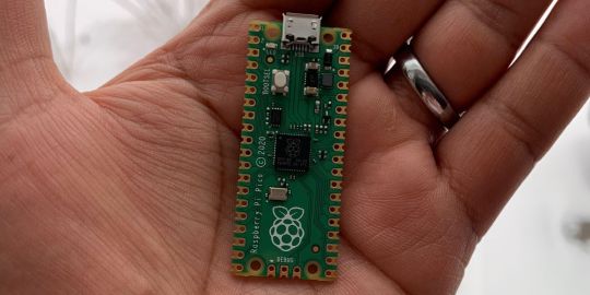
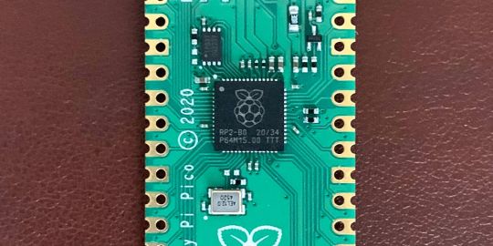
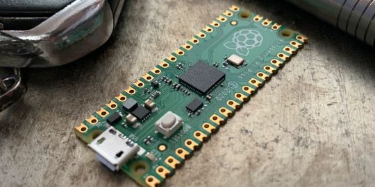
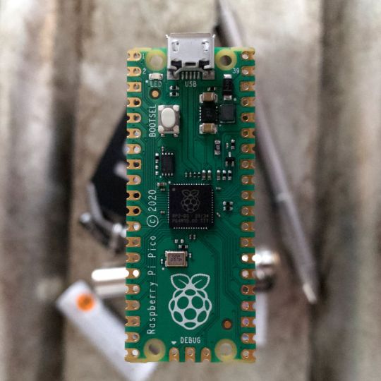
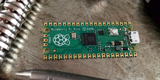
A Peek at the Pico, Raspberry Pi's Newest Petite Powerhouse
Raspberry Pi Pico
8.80 / 10
Read Reviews
Read More Reviews
Read More Reviews
Read More Reviews
Read More Reviews
Read More Reviews


Shop Now
Meet the new Raspberry Pi Pico; a tiny microcontroller filled with big possibilities.
Specifications
Brand: Raspberry Pi
CPU: Dual-core 133Mhz ARM
Memory: 264Kb
Ports: microUSB
Pros
Powerful ARM Processor
Micro-USB Connectivity
Breadboard Mountable
Easy-To-Use Interface
Absolutely Adorable
Inexpensive
Cons
No Wi-Fi or Bluetooth connectivity
No Header Pins
I/O Port Labelling on One Side Only
No USB-C Connectivity
Buy This Product
Raspberry Pi Pico other
Shop
// Bottom var galleryThumbs1 = new Swiper('.gallery-thumbs-1', { spaceBetween: 10, slidesPerView: 10, freeMode: true, watchSlidesVisibility: true, watchSlidesProgress: true, centerInsufficientSlides: true, allowTouchMove: false, preventClicks: false, breakpoints: { 1024: { slidesPerView: 6, } }, }); // Top var galleryTop1 = new Swiper('.gallery-top-1', { spaceBetween: 10, allowTouchMove: false, loop: true, preventClicks: false, breakpoints: { 1024: { allowTouchMove: true, } }, navigation: { nextEl: '.swiper-button-next', prevEl: '.swiper-button-prev', }, thumbs: { swiper: galleryThumbs1 } });
We’ve managed to get our hands on the coveted Raspberry Pi Pico. Today, we’re going to be looking at some of the most important features and putting it toe-to-toe with some of the biggest names in small electronics.
We’ll be showing you what the Pico can do, and we’ll get you started with MicroPython, one of Pico’s supported programming languages. We’ll even offer up some code to try in case you decide to buy a Pico of your own.
What Is a Raspberry Pi Pico?
Raspberry Pi Pico is a new budget microcontroller designed by Raspberry Pi. It’s a tiny computer built around a single chip, with onboard memory, and programmable in/out ports. Historically, microcontrollers are used in a variety of devices from medical implants to power tools. If you have an electronic device sitting in your vicinity, there’s a good chance that there’s a microcontroller inside of it.
Key Features of the Pico

The Pico is built around the RP2040 microcontroller chip, which was designed by Raspberry Pi UK. It’s a Dual-Core ARM processor with a flexible clock that can run up to 133 MHz. The Pico also supports 1.8-5.5 DC input voltage, has a micro-USB input port, and an onboard temperature sensor.
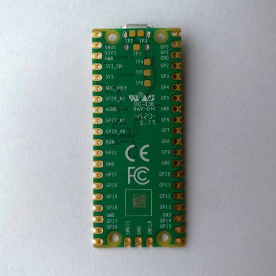
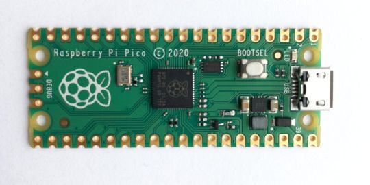
Flanking the chip on all sides are a series of castellations that allow easy soldering to a Veroboard or breadboard. This dual in-line package (DIP) style form factor is stackable, and can also be used in carrier board applications.
Technical Specifications
21 mm x 51 mm
264kb on-chip RAM
2 MB on-board QSPI flash
2 UART
26 GPIO
2 SPI controllers
2 ISC controllers
16 PWM channels
Accelerated integer and floating-point libraries
3-pin ARM Serial Wire Debug (SWD) port
What’s So Special About the Pi Pico?
The Pi Pico is a different kind of microcontroller. It’s Raspberry Pi’s first, and it features ARM technology in its RP2040 silicon chip. Many technology companies are embracing silicon ARM chips, with major manufacturers like Apple leading the charge.
The punchy little Pico packs a staggering 26 multifunction general purpose input/output (GPIO) ports, including 3 that are analog. Alongside these ports are 8 programmable input/output (PIO) ports. Compare this to other microcontrollers like the Arduino Nano, and the Pico packs roughly 18% more GPIO capability.
The most considerable difference between the Pico and its competitors, however, is the $4 price tag. Low cost is the main selling point of this unique offering.
At launch, many online retailers sold out of the device due to the interest and Raspberry Pi’s favorable reputation. By setting the price so low, the Pico opens the door for a new class of high-powered, budget microcontrollers.
There are many potential applications for the new Pico. With its onboard temperature sensor, the device is an obvious choice for IoT projects.
One talented retro gaming enthusiast even used a Pico to build a gaming console with full VGA video support.
youtube
This means that makers who have been curious about Raspberry Pi, or microcontrollers in general, now have the ability to experiment for less than the price of a fancy cup of coffee.
Related: The Raspberry Pi Comes of Age With the Pi 400 Desktop
The Raspberry Pi Pico Processor
The RP2040 ARM chip is an interesting choice for the Pico. At 133MHz, the chip is capable of leaving more expensive boards, like the Arduino Uno, in the dust.
Using ARM processors seems to be an emerging trend in the world of microcontrollers. In addition to Raspberry Pi, both Sparkfun and Adafruit also offer boards with similar ARM technology.
The industry-wide switch was made for a single reason—speed. ARM processors give a considerable boost over standard Atmel chips. In a board this size, using an ARM processor is like dropping a fully kitted Porsche engine into a Volkswagen. On the other hand, many microcontrollers don’t require that much processing speed. Yet.
Ramping up performance means that makers who want to push the limits of the Pico will have an abundance of power to do so.
The I/O Ports
The GPIO ports on the Pi Pico feature several interesting functions for common uses such as operating a screen, running lighting, or incorporating servos/relays. Some functions of the GPIO are available on all ports, and some only work for specific uses. GPIO 25, for example, controls the Pico’s onboard LED, and GPIO 23 controls the onboard SMPS Power Save feature.
The Pico also has both VSYS (1.8V — 5.5V) and VBUS (5V when connected to USB) ports, which are designed to deliver current to the RP2040 and its GPIO. This means that powering the Pico can be done with or without the use of the onboard micro-USB.
A full list of the I/O ports is available on Raspberry Pi’s website in its complete Pico documentation.
Pico vs. Arduino vs. Others
One question on the minds of many makers is whether or not the Raspberry Pi Pico is better than Arduino?
That depends. Pound-for-pound, higher-end Arduino boards like the Portenta H7 make the Pico look like a toy. However, the steep cost for a board of that caliber might be a tough pill for the microcontroller hobbyist to swallow. That's why the smaller price tag on the Pico makes it a win for makers who enjoy low-risk experimentation.
Along with minimal cost, the Raspberry Pi jams an extensive feature set into the Pico, comparable to boards like the Teensy LC, and the ESP32. But neither of these competitors manage to challenge the budget-friendly Pico on price.
That's what makes the Pico such a fantastic value, and a great choice for hobbyists and power users alike.
The Pi Pico: What’s Not To Love?
Unfortunately, to drive the price of the Pico down, Raspberry Pi had to make a few compromises. The most notable of which is the lack of an onboard radio module. Neither Bluetooth nor Wi-Fi is supported without add-ons.
The Wi-Fi limitation can be eliminated by adding a module like the ESP-01. Bluetooth support may prove a bit more challenging. If you need an all-in-one solution for your products, you’re better off skipping the Pico, and spending a little extra for something like the Pi Zero W, or ESP32.
Additionally, many early adopters are complaining about the lack of GPIO labeling on the top of the board. Raspberry Pi provides an extensive amount of documentation on its website to address this, but pointing-and-clicking, or thumbing through paperwork when you have a hot soldering iron in your hands isn’t often desirable.
Lastly, the lack of I/O pin headers is something of an issue for some, as it means less convenience when swapping I/O components. This minor annoyance can be solved via the use of leads, soldering the component wiring directly to the Pico, or using a breadboard.
If you’ve been using microcontrollers or small electronics for any period of time, then an unpopulated board is most likely a non-issue. Of course, you could also add your own pin headers if you plan on regular experimentation with different external components.
The final rub with the Pico is the micro-USB port. With many other microcontrollers like the Portenta H7 moving toward USB-C, Raspberry Pi's micro-USB port seems dated.
Logically however, the decision to use micro-USB makes sense. It was done by Raspberry Pi to keep costs as low as possible, and to keep interface capability almost universal. Everyone we know has at least a few micro-USB cables tucked away somewhere in their homes.
However, with future versions, a USB-C interface would be a nice addition to an already spectacular package.
Related: A Beginners Guide To Breadboarding With Raspberry Pi
Programming the Raspberry Pi Pico
Interfacing with the Pi Pico can be done via C/C++, or via MicroPython in the Read-Eval-Print-Loop or REPL (pronounced “Reh-pul”). The REPL is essentially a command line interface that runs line-by-line code in a loop.
In order to access the REPL, you’ll need to install MicroPython onto the Pico. This process is simple and only involves four steps.
Installing MicroPython
Download MicroPython for Raspberry Pi Pico from the Raspberry Pi Website
Connect the Pico to your computer via micro-USB while holding the BOOTSEL button
Wait for the Pico to appear as an external drive
Copy the MicroPython file to the Pi Pico, and it will automatically reboot
You can access the REPL in a number of ways. We used the screen command in a macOS terminal window to access the serial bus connected to the Pico. To accomplish this with Terminal, you’ll first open a new terminal window, then type ls /dev/tty*
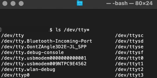
From there, find the port where the Pico is connected. It should be labeled something like /dev/tty.usbmodem0000000000001. Then run the command:
screen /dev/tty.usbmodem0000000000001
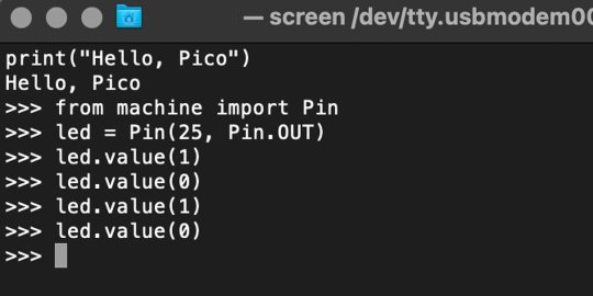
Your cursor should change. Hit Return and the cursor will change again to >>>.
In the image below we've included the classic Hello World (Hello, Pico) command-line program in the REPL, along with a few lines of code that will turn the Pico's LED on and off. Feel free to try them yourself.
For more information, we recommend you invest in the official starter guide to MicroPython that Raspberry Pi has published on their website.
Download: MicroPython for Raspberry Pi Pico (free)
Using the Raspberry Pi Pico With Thonny
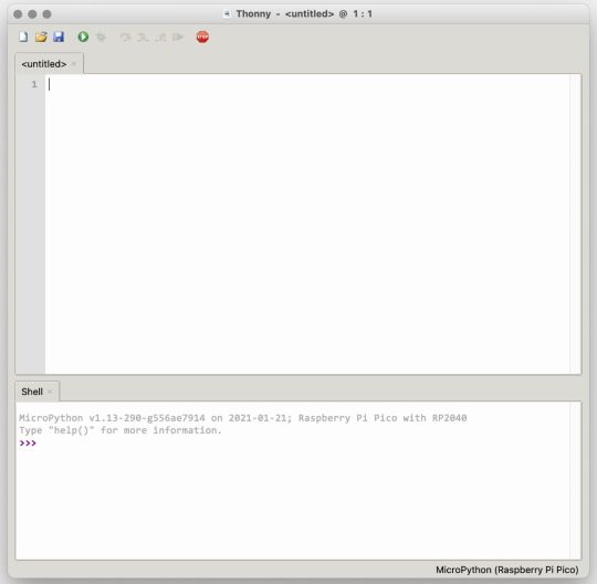
If you’re looking for a more proper coding environment, the Raspberry Pi Pico will also allow access to the REPL with Thonny. To enable this feature, first download and install Thonny. Once installed, connect your Pi Pico. Open Thonny and you'll see information indicating your Pico is connected in the Shell.
At the bottom right of the screen, you should see a version of Python. Click this version and select MicroPython (Raspberry Pi Pico) from the drop-down menu.
Now you can type commands into the Shell, or you can use Thonny’s editor to write or import multiple lines of code.
The abundance of interface possibilities make the Raspberry Pi Pico easy to program. For those who are familiar with MicroPython, this should be nothing new. For beginners, however, Thonny provides a powerful interface and debugger to get started with programming.
Download: Thonny (Free) Windows | Mac
Should I Buy the Raspberry Pi Pico?
The Raspberry Pi Pico is a powerful budget board that is perfect for hobbyists, or makers just starting out with microcontrollers. The documentation, low cost, and wide range of possibilities for the Pico also make it a great choice for seasoned small electronics wizards. If you’re a DIYer who loves to tinker, or you just want to challenge yourself to a weekend project, then you’ll love playing with the Pico.
On the other hand, if you don't have one or more projects in mind that need a microcontroller, then this board is probably not for you. Also, if your project needs Wi-Fi connectivity or Bluetooth, then the Pico won’t scratch that itch. And finally, for users who aren’t comfortable learning MicroPython, or exploring C/C++, the Pico isn't ideal. And remember: this Raspberry Pi is not like the others. It will not run a full Linux operating system.
But, if you dream in Python, or if you love the smell of solder, then you won't regret grabbing this tiny powerhouse. Most of all, if the sight of the sports-car-sleek RP2040 gets your creative gears turning, then we think you’ll really benefit from picking up the Pico.
Serving up Several Sweet Possibilities
While it isn’t perfect, the Raspberry Pi Pico is a strong entry into the world of microcontrollers. The reputation that Raspberry Pi has built for quality electronic components at a relatively low price extends to the Pico.
It’s everything a Raspberry Pi should be: small, sweet, and superb. It’s beautifully designed, and extremely inexpensive. But the best part isn’t the looks or the low cost.
The best part about this small wonder is picking it up, and holding it in your hands. It's feeling the tug of electronic inspiration. It's realizing just how powerful the Pico is, and what it means for microcontrollers going forward.
And truthfully, we think it's amazing that something as small as the Pico can offer so many unique possibilities.
A Peek at the Pico, Raspberry Pi's Newest Petite Powerhouse published first on http://droneseco.tumblr.com/
0 notes
Text
A Peek at the Pico, Raspberry Pi's Newest Petite Powerhouse
Raspberry Pi Pico
8.80 / 10
Read Reviews
Read More Reviews
Read More Reviews
Read More Reviews
Read More Reviews
Read More Reviews

Shop Now
Meet the new Raspberry Pi Pico; a tiny microcontroller filled with big possibilities.
Specifications
Brand: Raspberry Pi
CPU: Dual-core 133Mhz ARM
Memory: 264Kb
Ports: microUSB
Pros
Powerful ARM Processor
Micro-USB Connectivity
Breadboard Mountable
Easy-To-Use Interface
Absolutely Adorable
Inexpensive
Cons
No Wi-Fi or Bluetooth connectivity
No Header Pins
I/O Port Labelling on One Side Only
No USB-C Connectivity
Buy This Product
Raspberry Pi Pico other
Shop
// Bottom var galleryThumbs1 = new Swiper('.gallery-thumbs-1', { spaceBetween: 10, slidesPerView: 10, freeMode: true, watchSlidesVisibility: true, watchSlidesProgress: true, centerInsufficientSlides: true, allowTouchMove: false, preventClicks: false, breakpoints: { 1024: { slidesPerView: 6, } }, }); // Top var galleryTop1 = new Swiper('.gallery-top-1', { spaceBetween: 10, allowTouchMove: false, loop: true, preventClicks: false, breakpoints: { 1024: { allowTouchMove: true, } }, navigation: { nextEl: '.swiper-button-next', prevEl: '.swiper-button-prev', }, thumbs: { swiper: galleryThumbs1 } });
We’ve managed to get our hands on the coveted Raspberry Pi Pico. Today, we’re going to be looking at some of the most important features and putting it toe-to-toe with some of the biggest names in small electronics.
We’ll be showing you what the Pico can do, and we’ll get you started with MicroPython, one of Pico’s supported programming languages. We’ll even offer up some code to try in case you decide to buy a Pico of your own.
What Is a Raspberry Pi Pico?
Raspberry Pi Pico is a new budget microcontroller designed by Raspberry Pi. It’s a tiny computer built around a single chip, with onboard memory, and programmable in/out ports. Historically, microcontrollers are used in a variety of devices from medical implants to power tools. If you have an electronic device sitting in your vicinity, there’s a good chance that there’s a microcontroller inside of it.
Key Features of the Pico
The Pico is built around the RP2040 microcontroller chip, which was designed by Raspberry Pi UK. It’s a Dual-Core ARM processor with a flexible clock that can run up to 133 MHz. The Pico also supports 1.8-5.5 DC input voltage, has a micro-USB input port, and an onboard temperature sensor.
Flanking the chip on all sides are a series of castellations that allow easy soldering to a Veroboard or breadboard. This dual in-line package (DIP) style form factor is stackable, and can also be used in carrier board applications.
Technical Specifications
21 mm x 51 mm
264kb on-chip RAM
2 MB on-board QSPI flash
2 UART
26 GPIO
2 SPI controllers
2 ISC controllers
16 PWM channels
Accelerated integer and floating-point libraries
3-pin ARM Serial Wire Debug (SWD) port
What’s So Special About the Pi Pico?
The Pi Pico is a different kind of microcontroller. It’s Raspberry Pi’s first, and it features ARM technology in its RP2040 silicon chip. Many technology companies are embracing silicon ARM chips, with major manufacturers like Apple leading the charge.
The punchy little Pico packs a staggering 26 multifunction general purpose input/output (GPIO) ports, including 3 that are analog. Alongside these ports are 8 programmable input/output (PIO) ports. Compare this to other microcontrollers like the Arduino Nano, and the Pico packs roughly 18% more GPIO capability.
The most considerable difference between the Pico and its competitors, however, is the $4 price tag. Low cost is the main selling point of this unique offering.
At launch, many online retailers sold out of the device due to the interest and Raspberry Pi’s favorable reputation. By setting the price so low, the Pico opens the door for a new class of high-powered, budget microcontrollers.
There are many potential applications for the new Pico. With its onboard temperature sensor, the device is an obvious choice for IoT projects.
One talented retro gaming enthusiast even used a Pico to build a gaming console with full VGA video support.
youtube
This means that makers who have been curious about Raspberry Pi, or microcontrollers in general, now have the ability to experiment for less than the price of a fancy cup of coffee.
Related: The Raspberry Pi Comes of Age With the Pi 400 Desktop
The Raspberry Pi Pico Processor
The RP2040 ARM chip is an interesting choice for the Pico. At 133MHz, the chip is capable of leaving more expensive boards, like the Arduino Uno, in the dust.
Using ARM processors seems to be an emerging trend in the world of microcontrollers. In addition to Raspberry Pi, both Sparkfun and Adafruit also offer boards with similar ARM technology.
The industry-wide switch was made for a single reason—speed. ARM processors give a considerable boost over standard Atmel chips. In a board this size, using an ARM processor is like dropping a fully kitted Porsche engine into a Volkswagen. On the other hand, many microcontrollers don’t require that much processing speed. Yet.
Ramping up performance means that makers who want to push the limits of the Pico will have an abundance of power to do so.
The I/O Ports
The GPIO ports on the Pi Pico feature several interesting functions for common uses such as operating a screen, running lighting, or incorporating servos/relays. Some functions of the GPIO are available on all ports, and some only work for specific uses. GPIO 25, for example, controls the Pico’s onboard LED, and GPIO 23 controls the onboard SMPS Power Save feature.
The Pico also has both VSYS (1.8V — 5.5V) and VBUS (5V when connected to USB) ports, which are designed to deliver current to the RP2040 and its GPIO. This means that powering the Pico can be done with or without the use of the onboard micro-USB.
A full list of the I/O ports is available on Raspberry Pi’s website in its complete Pico documentation.
Pico vs. Arduino vs. Others

One question on the minds of many makers is whether or not the Raspberry Pi Pico is better than Arduino?
That depends. Pound-for-pound, higher-end Arduino boards like the Portenta H7 make the Pico look like a toy. However, the steep cost for a board of that caliber might be a tough pill for the microcontroller hobbyist to swallow. That's why the smaller price tag on the Pico makes it a win for makers who enjoy low-risk experimentation.
Along with minimal cost, the Raspberry Pi jams an extensive feature set into the Pico, comparable to boards like the Teensy LC, and the ESP32. But neither of these competitors manage to challenge the budget-friendly Pico on price.
That's what makes the Pico such a fantastic value, and a great choice for hobbyists and power users alike.
The Pi Pico: What’s Not To Love?
Unfortunately, to drive the price of the Pico down, Raspberry Pi had to make a few compromises. The most notable of which is the lack of an onboard radio module. Neither Bluetooth nor Wi-Fi is supported without add-ons.
The Wi-Fi limitation can be eliminated by adding a module like the ESP-01. Bluetooth support may prove a bit more challenging. If you need an all-in-one solution for your products, you’re better off skipping the Pico, and spending a little extra for something like the Pi Zero W, or ESP32.
Additionally, many early adopters are complaining about the lack of GPIO labeling on the top of the board. Raspberry Pi provides an extensive amount of documentation on its website to address this, but pointing-and-clicking, or thumbing through paperwork when you have a hot soldering iron in your hands isn’t often desirable.
Lastly, the lack of I/O pin headers is something of an issue for some, as it means less convenience when swapping I/O components. This minor annoyance can be solved via the use of leads, soldering the component wiring directly to the Pico, or using a breadboard.
If you’ve been using microcontrollers or small electronics for any period of time, then an unpopulated board is most likely a non-issue. Of course, you could also add your own pin headers if you plan on regular experimentation with different external components.
The final rub with the Pico is the micro-USB port. With many other microcontrollers like the Portenta H7 moving toward USB-C, Raspberry Pi's micro-USB port seems dated.
Logically however, the decision to use micro-USB makes sense. It was done by Raspberry Pi to keep costs as low as possible, and to keep interface capability almost universal. Everyone we know has at least a few micro-USB cables tucked away somewhere in their homes.
However, with future versions, a USB-C interface would be a nice addition to an already spectacular package.
Related: A Beginners Guide To Breadboarding With Raspberry Pi
Programming the Raspberry Pi Pico
Interfacing with the Pi Pico can be done via C/C++, or via MicroPython in the Read-Eval-Print-Loop or REPL (pronounced “Reh-pul”). The REPL is essentially a command line interface that runs line-by-line code in a loop.
In order to access the REPL, you’ll need to install MicroPython onto the Pico. This process is simple and only involves four steps.
Installing MicroPython
Download MicroPython for Raspberry Pi Pico from the Raspberry Pi Website
Connect the Pico to your computer via micro-USB while holding the BOOTSEL button
Wait for the Pico to appear as an external drive
Copy the MicroPython file to the Pi Pico, and it will automatically reboot
You can access the REPL in a number of ways. We used the screen command in a macOS terminal window to access the serial bus connected to the Pico. To accomplish this with Terminal, you’ll first open a new terminal window, then type ls /dev/tty*

From there, find the port where the Pico is connected. It should be labeled something like /dev/tty.usbmodem0000000000001. Then run the command:
screen /dev/tty.usbmodem0000000000001
Your cursor should change. Hit Return and the cursor will change again to >>>.
In the image below we've included the classic Hello World (Hello, Pico) command-line program in the REPL, along with a few lines of code that will turn the Pico's LED on and off. Feel free to try them yourself.

For more information, we recommend you invest in the official starter guide to MicroPython that Raspberry Pi has published on their website.
Download: MicroPython for Raspberry Pi Pico (free)
Using the Raspberry Pi Pico With Thonny

If you’re looking for a more proper coding environment, the Raspberry Pi Pico will also allow access to the REPL with Thonny. To enable this feature, first download and install Thonny. Once installed, connect your Pi Pico. Open Thonny and you'll see information indicating your Pico is connected in the Shell.
At the bottom right of the screen, you should see a version of Python. Click this version and select MicroPython (Raspberry Pi Pico) from the drop-down menu.
Now you can type commands into the Shell, or you can use Thonny’s editor to write or import multiple lines of code.
The abundance of interface possibilities make the Raspberry Pi Pico easy to program. For those who are familiar with MicroPython, this should be nothing new. For beginners, however, Thonny provides a powerful interface and debugger to get started with programming.
Download: Thonny (Free) Windows | Mac
Should I Buy the Raspberry Pi Pico?
The Raspberry Pi Pico is a powerful budget board that is perfect for hobbyists, or makers just starting out with microcontrollers. The documentation, low cost, and wide range of possibilities for the Pico also make it a great choice for seasoned small electronics wizards. If you’re a DIYer who loves to tinker, or you just want to challenge yourself to a weekend project, then you’ll love playing with the Pico.
On the other hand, if you don't have one or more projects in mind that need a microcontroller, then this board is probably not for you. Also, if your project needs Wi-Fi connectivity or Bluetooth, then the Pico won’t scratch that itch. And finally, for users who aren’t comfortable learning MicroPython, or exploring C/C++, the Pico isn't ideal. And remember: this Raspberry Pi is not like the others. It will not run a full Linux operating system.
But, if you dream in Python, or if you love the smell of solder, then you won't regret grabbing this tiny powerhouse. Most of all, if the sight of the sports-car-sleek RP2040 gets your creative gears turning, then we think you’ll really benefit from picking up the Pico.
Serving up Several Sweet Possibilities
While it isn’t perfect, the Raspberry Pi Pico is a strong entry into the world of microcontrollers. The reputation that Raspberry Pi has built for quality electronic components at a relatively low price extends to the Pico.
It’s everything a Raspberry Pi should be: small, sweet, and superb. It’s beautifully designed, and extremely inexpensive. But the best part isn’t the looks or the low cost.
The best part about this small wonder is picking it up, and holding it in your hands. It's feeling the tug of electronic inspiration. It's realizing just how powerful the Pico is, and what it means for microcontrollers going forward.
And truthfully, we think it's amazing that something as small as the Pico can offer so many unique possibilities.
A Peek at the Pico, Raspberry Pi's Newest Petite Powerhouse published first on http://droneseco.tumblr.com/
0 notes