
Last Seen Blogs

ziubalder2
Sweet & bitter

lindegaardmalmberg13
The Love of Cleveland 550

atomsminecraft
I’m Getting More Crazy Every Year 😍

davinikart
Davinik

jennifer1212
Jennifer
Text
Simple Image Forensics
Saat ini, kita familar banget dengan berbagai gambar editan yang tersebar di internet. Sesimpel menghilangkan imperfection di muka, mengganti latar belakang foto (sering ditemui untuk keperluan administrasi, hehe), atau yang lebih advance lagi adalah sengaja mengubah untuk menyisipkan pesan tersembunyi di dalam gambar. Untuk editan satu ini pastinya akan lebih sulit untuk diidentifikasi dibandingkan editan lucu-lucuan, oleh karena itu kita akan membahas sedikit dari image forensics, setidaknya tool apa saja sih yang bisa digunakan untuk image forensics.
JPEGsnoop
JPEGsnoop itu salah satu aplikasi yang bisa digunakan untuk melakukan forensik gambar yang gratis dan mudah digunakan. JPEGsnoop akan memberikan informasi mengenai metadata suatu gambar hingga bisa memprediksi apakah gambar tersebut telah diubah atau tidak.
Untuk file zipnya bisa didownload di link ini.
Pada kesempatan ini, gambar yang akan digunakan untuk pemrosesan forensik digital adalah gambar ini:

File aslinya bisa diakses di link ini.
Menggunakan tool JPEGsnoop, kita bisa melihat metadata dan analisis dari gambar tersebut.

Sejujurnya, tidak semua informasi yang ditampilkan saya pahami (😄), tapi ada satu baris yang sangat menarik perhatian. Ketika kita scroll ke bagian paling bawah, akan ada informasi mengenai apakah gambar tersebut sudah dilakukan proses pengubahan atau belum. Dan hasilnya adalah:

Gambar tersebut sudah diproses atau dilakukan pengubahan. Sehingga dengan tool ini kita bisa mengetahui apakah benar gambar ini telah diubah? Dan jenis pengubahannya dapat diketahui melalui analisis metadata atau bisa menggunakan alat bantu lainnya, tergantung jenis pengubahan gambarnya.
Forensically
Forensically ini juga gratis dan mudah digunakan. Untuk mengakses, kita cukup menggunakan browser dan masukkan alamat https://29a.ch/photo-forensics/#forensic-magnifier.
Forensically memiliki beberapa fitur yang bisa dipelajari:
1. Magnifier atau kaca pembesar
2. Clone Detection
3. Error Level Analysis (ELA)
4. Noise Analysis
5. Level Sweep
6. Luminance Gradient
7. Principal Component Analysis
8. Metadata
9. Thumbnail Analysis
10. JPEG Analysis
11. String Extraction
Beberapa pilihan tools tersebut bisa digunakan untuk mendeteksi anomali yang ada di suatu gambar. Dan kali ini, gambar yang digunakan masih sama.
Menggunakan tool Error Level Analysis yang biasa digunakan untuk mendeteksi adanya manipulasidalam suatu gambar, hasil yang didapat adalah seperti ini:

Gambar di atas merupakan hasil dari penggunaan Error Level Analysis. Sejauh ini terlihat tidak ada yang aneh, namun jika diperhatikan, langitnya terlihat seperti ada lingkaran yang memiliki beberapa warna (sepertinya memusat di matahari?) namun di gambar untuk bagian langit yang berada di antara dedaunan (yang menjadi background), warnanya hitam polos, berbeda dengan langit yang memiliki beberapa warna tersebut.

Kemudian ini hasil menggunakan Clone Detection:

Dari hasil tersebut, terdeteksi ada hasil clone dengan panjang yang sama. Namun memang kalau dilihat tanpa alat apapun, rasanya tidak ada yang aneh. Tapi setelah digunakan clone analysis memang ada sesuatu yang patut dicurigai karena alat ini menunjukkan kemungkinan manipulasi dengan menampilkan garis-garis merah seperti gambar di atas.
Beberapa tool juga telah saya lakukan, tapi belum bisa mendeteksi keanehan yang ada pada gambar tersebut. Karena memang saya juga tidak memiliki foto asli yang sebelum diubah (anggap saja ini latihan forensik digital). Ada yang punya pendapat mungkin? Let me know!
Referensi:
- https://headt.eu/How-to-Detect-Image-Manipulations-Part-2/
0 notes
Text
SQL Injection - DVWA
Hello!

Mungkin ketika mendengar kata ‘hacker’, yang terbesit adalah penjahat kriminal dalam konotasi negatif. Sebetulnya, hacker merupakan seseorang yang memiliki pengetahuan mengenai security dari suatu sistem komputer, sehingga ia bisa mencari celah keamanan dan menembus suatu sistem dengan memanfaatkan kelemahan dan celah tersebut. Tapi terkadang, hacking menjadi salah satu metode untuk mengecek apakah sistem milik kita sudah aman? Kalau hacker saja bisa menembus sistem tersebut, tandanya sistem kita belum cukup aman.
Saat ini banyak platform yang disediakan sebagai metode untuk mengetahui kelemahan suatu sistem. Dan pada post kali ini kita akan membahas sedikit dari DVWA.
Apa itu DVWA?
Dari web DVWA, Damn Vulnerable Web App adalah aplikasi web PHP/MySQL yang sangat rentan dengan tujuan utamanya adalah untuk menjadi bantuan bagi profesional keamanan untuk menguji keterampilan dan alat mereka di lingkungan hukum, membantu pengembang web lebih memahami proses mengamankan aplikasi web dan membantu guru/siswa untuk mengajar/mempelajari keamanan aplikasi web di lingkungan ruang kelas. Meskipun begitu, ilmu yang telah kita dapat setelah bermain dengan DVWA tentunya harus digunakan dengan bijak. Dan pada kesempatan ini juga kita akan belajar sedikit dari DVWA hanya untuk pengetahuan, bukan untuk berbuat kriminal.
So here we go!
Untuk menginstall DVWA ada beberapa cara. Namun untuk yang sudah terbiasa dengan penggunaan docker, bisa install dengan melihat cara disini: https://github.com/opsxcq/docker-vulnerable-dvwa
Setelah terinstall dan telah login, kita dapat memilih beberapa case yang tersedia dengan 3 tingkatan kesulitan mulai dari low, hingga high. Dan pada kesempatan kali ini, kita akan membahas SQL Injection dengan tingkat kesulitan low.
SQL INJECTION
SQL injection adalah teknik eksploitasi dengan cara memodifikasi perintah SQL pada form input aplikasi yang memungkinkan penyerang untuk dapat mengirimkan sintaks ke database aplikasi.
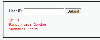
Ketika kita mengklik “SQL Injection”, halaman yang terlihat hanyalah berisi sebuah kotak di mana kita dapat memasukkan user ID. Seperti ketika kita memasukkan user ID 2, maka akan keluar output seperti ini:
Mari kita ulas beberapa injection yang telah dilakukan.
Menampilkan seluruh user yang terdaftar. Dalam SQL, ketika kita memasukkan query 1=1 artinya kita mengeluarkan semua jawaban karena dianggap semuanya always true. Biasanya query yang digunakan adalah 1=1-- di mana ‘--’ digunakan sebagai comment. Namun hal itu tidak berhasil kalau kita menuliskan comment ‘--’. Tapi ketika kita ganti dengan ‘#’, maka akan muncul hasil seperti ini:

Semua user ditampilkan! Dan seperti inilah contoh SQL injection. Namun yang kita lakukan belum termasuk tingkat kriminal karena query yang ditampilkan memang yang bisa ditampilkan. Mari lanjut ke injeksi kedua.
Menampilkan information_schema
Input yang dimasukkan: x’ UNION SELECT table_name,null FROM information_schema.tables #
Hasil:

Query ini bermaksud untuk menampilkan information_schema yang biasa bisa ditampilkan pada tabel SQL. Bukan sesuatu seperti injeksi sih, tetapi dengan ini kita bisa mengetahui struktur tabelnya dan bisa menjadi referensi injeksi lainnya. Dari struktur tabel ini kita bisa melihat dan menentukan informasi apa yang ingin kita gali. Biasanya password tidak bisa kita akses namun kali ini kita akan mencobanya karena main goal kita adalah melihat password setiap user.
Melihat table apa saja yang tersedia.
Input: : x’ UNION SELECT table_name,null FROM information_schema.tables WHERE table_schema=database #
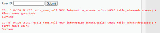
Dalam query, wajib menggunakan ‘#’ karena tanpanya kita tidak bisa mengakses hal tersebut. Ini akan kita ulas di akhir postingan karena hampir query yang kita masukkan menyertakan ‘#’ di akhirnya.
Query ini mengembalikan semua nama tabel yang ada di database. Kita bisa melihat ada tabel guestbook dan users. Mari kita lihat tabel users karena biasanya disitulah disimpan data password.
Menampilkan password
Input: test' and 1=0 union select null, concat(first_name,0x0a,last_name,0x0a,user,0x0a,password) from users #
Hasil:

Ta-da! Baris paling bawah merupakan password masing-masing user yang telah dihash. Tentunya kita bisa mengetahui hashed password tersebut dengan meng-crack nya dengan sangat mudah. Salah satunya dengan menggunakan link https://crackstation.net/.
Kenapa kita bisa menginjeksi SQL tersebut? Seperti yang telah disebut sebelumnya, seluruh query milik kita selalu diakhiri dengan ‘#’. Hal ini karena input dari kita tidak divalidasi oleh SQL dan tidak ada pembatasan special character yang bisa dimasukkan. Coba ketika tidak diakhiri dengan ‘#’, maka akan muncul:
You have an error in your SQL syntax; check the manual that corresponds to your MariaDB server version for the right syntax to use near ''' at line 1
Sehingga untuk pemilik web, perhatikan validasi input pengguna dan gunakan pembatasan special character, jangan sampai ada beberapa karakter yang lolos (seperti yang kita lakukan barusan). Dan kalau perlu, tambahkan security protocol yang lebih agar terhindari dari berbagai SQL Injection.
Yak, sekian pembahasan SQL Injection - Low kali ini. Terima kasih dan ditunggu masukannya!

0 notes
Text
Anonymization in Our Daily Life

Sepertinya penggunaan VPN pada zaman sekarang merupakan hal yang biasa, bahkan wajib untuk mengakses beberapa situs tertentu salah satunya karena diblock oleh pemerintah. Mungkin pembaca post ini bisa jadi sedang menggunakan VPN, hehe. Tapi pada intinya, pengguna internet saat ini sudah tidak asing dengan istilah VPN dan penggunaannya.
Bahkan kalau kita menengok ke beberapa e-commerce, banyak yang menjual VPN berbayar dengan keuntungan yang tentunya lebih banyak dibandingkan VPN gratis yang mudah didapatkan. Karena pada saat ini mungkin saja layanan VPN gratis tidak mampu memenuhi kebutuhannya tapi namanya gratis. Sehingga banyak juga yang menyediakan layanan VPN namun berbayar.
Namun sebelumnya, VPN itu apa?
Singkatnya, VPN merupakan sebuah layanan yang digunakan untuk mengakses sebuah situs dengan mengubah beberapa informasi agar akses kita menjadi lebih aman dan private, entah itu dengan mengubah identitas atau bisa saja tidak diketahui sama sekali. Sebagai contoh ketika kita hendak mengakses situs X yang tidak bisa diakses di Indonesia, dengan VPN kita bisa mengubah identitas negara kita menjadi negara lain hingga kita bisa mengakses situs tersebut.
Bisa dikatakan VPN ini bertugas sebagai middleman di mana saat kita hendak mengakses suatu situs, VPN akan mengubah identitas kita sehingga yang diterima oleh situs tersebut bukanlah identitas asli kita. Akses kita akan dibawa ke suatu jalur lain, berbeda dengan jalur tanpa VPN sehingga situs tersebut akan mengenali kita dari jaringan yang berbeda. Dan VPN ini akan melakukan ekstraksi berupa enkripsi data kita agar lebih secure. Alasan keamanan ini bisa digunakan ketika kita hendak menukarkan data yang bersifat rahasia seperti data perbankan.
Dan ternyata, penggunaan VPN ini bisa menjadi salah satu teknik anti forensik, loh!
Singkatnya, anti forensik adalah upaya menghilangkan jejak dan barang bukti kejahatan digital. Jadi ketika seseorang dicurigai telah melakukan suatu kejahatan digital, penyidik akan kesulitan menghukumnya karena buktinya bisa jadi telah hilang atau kurang kuat.
Ada beberapa cara yang bisa ditempuh untuk melakukan anti forensik, salah satunya adalah teknik menghilangkan data (data hiding). Pada kasus penggunaan VPN ini, ada data yang disembunyikan atau dihilangkan pada saat mengakses suatu situs sehingga penyidik ketika melakukan penyelidikan siapa yang mengakses situs tersebut dikelabui oleh karena penggunaan VPN tersebut.
Teknik ini bisa dikenal dengan istilah anonymization, di mana personal identifier orang yang mengakses tersebut tidak diketahui oleh penyidik. Jadi secara tidak langsung, saat kita mengakses situs menggunakan VPN, kita telah melakukan anonymization. VPN pada awalnya dibuat bukan untuk menganonimkan pelaku kejahatan, namun ternyata penggunaan VPN ini bisa menjadi salah satu upaya anti forensik.
Selain penggunaan VPN, anonymization juga bisa dilakukan dengan beberapa cara lain seperti web anonymizer, the union router, dan browser extension.
Lantas, apakah berarti tidak boleh menggunakan VPN karena hal tersebut akan menyulitkan penyidik saat pemeriksaan?
Yah, selama tidak melakukan kejahatan sih... Tidak mengapa. Lagipula ada hal-hal yang memang kita tidak bisa mengakses situs yang mungkin saja penting bagi kita, namun tidak bisa diakses tanpa VPN.
Ternyata, anti forensik dengan cara anonymization sangat dekat pada kita sehari-hari 😏
Ditulis untuk memenuhi tugas mata kuliah Forensik Digital untuk tugas mengulas antiforensik (Khairunnisa Rifdah - 18218008)
Sumber:
1. https://www.niagahoster.co.id/blog/apa-itu-vpn/
2. https://resources.infosecinstitute.com/topic/spoofing-and-anonymization-hiding-network-activity/
0 notes
Text
Last, Insert Data into MySQL using PHP and Arduino IDE
Hello!
Perhaps this is my last project for this semester because the semester has finished! And all I must do is only pass the examination and hoping for the best result of this semester. Aamiin.
I want to start this post with expressing my greatest thank to my Embedded System’s lecturer, Mr Kusprasapta Mutijarsa for encouraging my class to mess with ESP32, learn a much about it, and soon to be implementing to our life. I hope so. Last year when I was a fresh year student, I had PRD class (similar to this class) but I think I didn’t get anything from the class. I’m still feeling strange with Arduino, I don’t know how embedded system works, even I don’t know there is a development board exist in this world except for Arduino Board. But after I take Embedded System class this semester, I’m feeling enlightened by the hands-on. I feel familiar with Arduino IDE, I know more about the embedded system, and also I FEEL THE BURNING SENSOR FOR MY LIFE okay this is a very interesting experience for me.
And also I want to deliver my thank to my group partner, Grace and Naomi for helping the project from the start until now. You can check their blog on this link!
Grace’s blog: https://coretangrace.blogspot.com/
Naomi’s blog: https://naomiylnd.wixsite.com/mysite
Okay, next. Enough for chitchat.
So this project is building an ESP32 client that makes an HTTP post request to a PHP script to insert data into MySQL Database. As usual this project according to randomnerdtutorial.com link. But I’m using DHT 11 sensor which is quite different from the link. If you using DHT 11 too, you can follow my code for Arduino IDE because the code provided by randomnerdtutorial is for BME280 sensor.
Okay let’s get started with these steps:
1. Hosting your PHP application and MySQL Database.
For this step, you can use Bluehost/digital ocean. But for this project, my classmate initiates to use his old domain for all class participant so I join to his domain.
2. Prepare MySQL Database
3. Insert Data in MySQL Database
You can use cPanel or other to set the MySQL Database. But my friend domain using cPanel so I’ll show the step using cPanel.
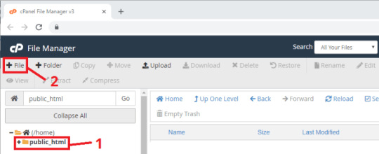
Search “File Manager”, select public_html option and press the “+ File” to create a new PHP file.
Create a new file and right-click the file that you’ve to create to edit the script. Copy this following code:
<?php /* Rui Santos Complete project details at https://RandomNerdTutorials.com/esp32-esp8266-mysql-database-php/ Permission is hereby granted, free of charge, to any person obtaining a copy of this software and associated documentation files. The above copyright notice and this permission notice shall be included in all copies or substantial portions of the Software. */ $servername = "localhost"; // REPLACE with your Database name $dbname = "REPLACE_WITH_YOUR_DATABASE_NAME"; // REPLACE with Database user $username = "REPLACE_WITH_YOUR_USERNAME"; // REPLACE with Database user password $password = "REPLACE_WITH_YOUR_PASSWORD"; // Keep this API Key value to be compatible with the ESP32 code provided in the project page. // If you change this value, the ESP32 sketch needs to match $api_key_value = "tPmAT5Ab3j7F9"; $api_key= $sensor = $location = $value1 = $value2 = $value3 = ""; if ($_SERVER["REQUEST_METHOD"] == "POST") { $api_key = test_input($_POST["api_key"]); if($api_key == $api_key_value) { $sensor = test_input($_POST["sensor"]); $location = test_input($_POST["location"]); $value1 = test_input($_POST["value1"]); $value2 = test_input($_POST["value2"]); $value3 = test_input($_POST["value3"]); // Create connection $conn = new mysqli($servername, $username, $password, $dbname); // Check connection if ($conn->connect_error) { die("Connection failed: " . $conn->connect_error); } $sql = "INSERT INTO SensorData (sensor, location, value1, value2, value3) VALUES ('" . $sensor . "', '" . $location . "', '" . $value1 . "', '" . $value2 . "', '" . $value3 . "')"; if ($conn->query($sql) === TRUE) { echo "New record created successfully"; } else { echo "Error: " . $sql . "<br>" . $conn->error; } $conn->close(); } else { echo "Wrong API Key provided."; } } else { echo "No data posted with HTTP POST."; } function test_input($data) { $data = trim($data); $data = stripslashes($data); $data = htmlspecialchars($data); return $data; }
Don’t forget to modify the dbname, username, and password with your credentials.
4. Display Database Content
Create another PHP file (the step is same with step 3) and copy this code:
<!DOCTYPE html> <html><body> <?php /* Rui Santos Complete project details at https://RandomNerdTutorials.com/esp32-esp8266-mysql-database-php/ Permission is hereby granted, free of charge, to any person obtaining a copy of this software and associated documentation files. The above copyright notice and this permission notice shall be included in all copies or substantial portions of the Software. */ $servername = "localhost"; // REPLACE with your Database name $dbname = "REPLACE_WITH_YOUR_DATABASE_NAME"; // REPLACE with Database user $username = "REPLACE_WITH_YOUR_USERNAME"; // REPLACE with Database user password $password = "REPLACE_WITH_YOUR_PASSWORD"; // Create connection $conn = new mysqli($servername, $username, $password, $dbname); // Check connection if ($conn->connect_error) { die("Connection failed: " . $conn->connect_error); } $sql = "SELECT id, sensor, location, value1, value2, value3, reading_time FROM SensorData ORDER BY id DESC"; echo '<table cellspacing="5" cellpadding="5"> <tr> <td>ID</td> <td>Sensor</td> <td>Location</td> <td>Value 1</td> <td>Value 2</td> <td>Value 3</td> <td>Timestamp</td> </tr>'; if ($result = $conn->query($sql)) { while ($row = $result->fetch_assoc()) { $row_id = $row["id"]; $row_sensor = $row["sensor"]; $row_location = $row["location"]; $row_value1 = $row["value1"]; $row_value2 = $row["value2"]; $row_value3 = $row["value3"]; $row_reading_time = $row["reading_time"]; // Uncomment to set timezone to - 1 hour (you can change 1 to any number) //$row_reading_time = date("Y-m-d H:i:s", strtotime("$row_reading_time - 1 hours")); // Uncomment to set timezone to + 4 hours (you can change 4 to any number) //$row_reading_time = date("Y-m-d H:i:s", strtotime("$row_reading_time + 4 hours")); echo '<tr> <td>' . $row_id . '</td> <td>' . $row_sensor . '</td> <td>' . $row_location . '</td> <td>' . $row_value1 . '</td> <td>' . $row_value2 . '</td> <td>' . $row_value3 . '</td> <td>' . $row_reading_time . '</td> </tr>'; } $result->free(); } $conn->close(); ?> </table> </body> </html>
Again, don’t forget to change dbname, username and password!
5. Prepare EPS32
You only need the ESP32 board, jumping wires, USB type-A cable, and DHT 11 sensor to do this project. The schematic is as usual, connect the + port from DHT 11 to 3V3 on ESP32, the out port to GPIO port and the - port to GROUND on ESP32.
After that, you can open your Arduino IDE and copy this code:
/*
Rui Santos
Complete project details at https://RandomNerdTutorials.com/esp32-esp8266-mysql-database-php/
Permission is hereby granted, free of charge, to any person obtaining a copy
of this software and associated documentation files.
The above copyright notice and this permission notice shall be included in all
copies or substantial portions of the Software.
*/
#ifdef ESP32
#include <WiFi.h>
#include <HTTPClient.h>
#else
#include <ESP8266WiFi.h>
#include <ESP8266HTTPClient.h>
#include <WiFiClient.h>
#endif
#include <Wire.h>
#include <DHT.h>
#define DHTPIN 21 // Digital pin connected to the DHT sensor
#define DHTTYPE DHT11 // DHT 11
DHT dht(DHTPIN, DHTTYPE);
// Replace with your network credentials
const char* ssid = "BK28";
const char* password = "Nisa123Rafif";
// REPLACE with your Domain name and URL path or IP address with path
const char* serverName = "https://hardyvalen.my.id/new_post_esp_data.php";
// Keep this API Key value to be compatible with the PHP code provided in the project page.
// If you change the apiKeyValue value, the PHP file /post-esp-data.php also needs to have the same key
String apiKeyValue = "tPmAT5Ab3j7F9";
String sensorName = "DHT11";
String sensorLocation = "Tangsel";
void setup() {
Serial.begin(115200);
WiFi.begin(ssid, password);
Serial.println("Connecting");
while(WiFi.status() != WL_CONNECTED) {
delay(500);
Serial.print(".");
}
Serial.println("");
Serial.print("Connected to WiFi network with IP Address: ");
Serial.println(WiFi.localIP());
// (you can also pass in a Wire library object like &Wire2)
dht.begin();
}
void loop() {
//Check WiFi connection status
if(WiFi.status()== WL_CONNECTED){
HTTPClient http;
// Your Domain name with URL path or IP address with path
http.begin(serverName);
// Specify content-type header
http.addHeader("Content-Type", "application/x-www-form-urlencoded");
// Prepare your HTTP POST request data
String httpRequestData = "api_key=" + apiKeyValue + "&sensor=" + sensorName
+ "&location=" + sensorLocation + "&value1=" + String(dht.readTemperature())
+ "&value2=" + String(dht.readHumidity()) + "";
Serial.print("httpRequestData: ");
Serial.println(httpRequestData);
// You can comment the httpRequestData variable above
// then, use the httpRequestData variable below (for testing purposes without the BME280 sensor)
//String httpRequestData = "api_key=tPmAT5Ab3j7F9&sensor=BME280&location=Office&value1=24.75&value2=49.54&value3=1005.14";
// Send HTTP POST request
int httpResponseCode = http.POST(httpRequestData);
// If you need an HTTP request with a content type: text/plain
//http.addHeader("Content-Type", "text/plain");
//int httpResponseCode = http.POST("Hello, World!");
// If you need an HTTP request with a content type: application/json, use the following:
//http.addHeader("Content-Type", "application/json");
//int httpResponseCode = http.POST("{\"value1\":\"19\",\"value2\":\"67\",\"value3\":\"78\"}");
if (httpResponseCode>0) {
Serial.print("HTTP Response code: ");
Serial.println(httpResponseCode);
}
else {
Serial.print("Error code: ");
Serial.println(httpResponseCode);
}
// Free resources
http.end();
}
else {
Serial.println("WiFi Disconnected");
}
//Send an HTTP POST request every 30 seconds
delay(30000);
}
Okay, after modifying the credentials and hosting name, you can upload your code and TARAAA! Open your domain name to see the miracle and this one is mine!
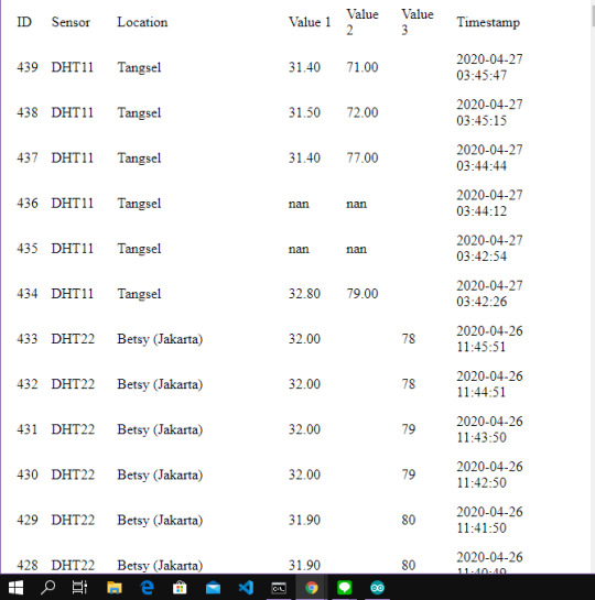
Because the domain is for all participant in the class, I can see the result from all of my friend.
Fiuh.
Finally, I have finished all of my assignment for this semester. Last but not least, I will explore more about the embedded system because I found this one is pretty interesting! Okay, wait for my next post, all! See you again!!
0 notes
Text
ESP32 Trying to Input Data on HTML
Hello!
As the title I state before, I’ll show you how to input data on HTML using ESP32. This project I made according to this link and I think the level of difficulty is 1 from 5. It was an easy peasy project but interesting! You can develop many things from this basic project. Okay let's start with the equipment:
ESP32 Board
USB Type-A Cable
PC/Laptop with Arduino IDE
Okay, enough!
And also you need to install ESP32 library, AsyncWebServer and AsyncTP libraries.
After that you can copy this code to your Arduino IDE:
/********* Rui Santos Complete project details at https://RandomNerdTutorials.com/esp32-esp8266-input-data-html-form/ Permission is hereby granted, free of charge, to any person obtaining a copy of this software and associated documentation files. The above copyright notice and this permission notice shall be included in all copies or substantial portions of the Software. *********/ #include <Arduino.h> #ifdef ESP32 #include <WiFi.h> #include <AsyncTCP.h> #else #include <ESP8266WiFi.h> #include <ESPAsyncTCP.h> #endif #include <ESPAsyncWebServer.h> AsyncWebServer server(80); // REPLACE WITH YOUR NETWORK CREDENTIALS const char* ssid = "REPLACE_WITH_YOUR_SSID"; const char* password = "REPLACE_WITH_YOUR_PASSWORD"; const char* PARAM_INPUT_1 = "input1"; const char* PARAM_INPUT_2 = "input2"; const char* PARAM_INPUT_3 = "input3"; // HTML web page to handle 3 input fields (input1, input2, input3) const char index_html[] PROGMEM = R"rawliteral( <!DOCTYPE HTML><html><head> <title>ESP Input Form</title> <meta name="viewport" content="width=device-width, initial-scale=1"> </head><body> <form action="/get"> input1: <input type="text" name="input1"> <input type="submit" value="Submit"> </form><br> <form action="/get"> input2: <input type="text" name="input2"> <input type="submit" value="Submit"> </form><br> <form action="/get"> input3: <input type="text" name="input3"> <input type="submit" value="Submit"> </form> </body></html>)rawliteral"; void notFound(AsyncWebServerRequest *request) { request->send(404, "text/plain", "Not found"); } void setup() { Serial.begin(115200); WiFi.mode(WIFI_STA); WiFi.begin(ssid, password); if (WiFi.waitForConnectResult() != WL_CONNECTED) { Serial.println("WiFi Failed!"); return; } Serial.println(); Serial.print("IP Address: "); Serial.println(WiFi.localIP()); // Send web page with input fields to client server.on("/", HTTP_GET, [](AsyncWebServerRequest *request){ request->send_P(200, "text/html", index_html); }); // Send a GET request to <ESP_IP>/get?input1=<inputMessage> server.on("/get", HTTP_GET, [] (AsyncWebServerRequest *request) { String inputMessage; String inputParam; // GET input1 value on <ESP_IP>/get?input1=<inputMessage> if (request->hasParam(PARAM_INPUT_1)) { inputMessage = request->getParam(PARAM_INPUT_1)->value(); inputParam = PARAM_INPUT_1; } // GET input2 value on <ESP_IP>/get?input2=<inputMessage> else if (request->hasParam(PARAM_INPUT_2)) { inputMessage = request->getParam(PARAM_INPUT_2)->value(); inputParam = PARAM_INPUT_2; } // GET input3 value on <ESP_IP>/get?input3=<inputMessage> else if (request->hasParam(PARAM_INPUT_3)) { inputMessage = request->getParam(PARAM_INPUT_3)->value(); inputParam = PARAM_INPUT_3; } else { inputMessage = "No message sent"; inputParam = "none"; } Serial.println(inputMessage); request->send(200, "text/html", "HTTP GET request sent to your ESP on input field (" + inputParam + ") with value: " + inputMessage + "<br><a href=\"/\">Return to Home Page</a>"); }); server.onNotFound(notFound); server.begin(); } void loop() { }
Don't forget to replace this part of the code:
const char* ssid = "REPLACE_WITH_YOUR_SSID"; const char* password = "REPLACE_WITH_YOUR_PASSWORD";
with your SSID and password.
Okay, after uploading the code you will see the result and don't forget to press enable button in ESP32 board. Before you press enable, you can open the serial monitor in Arduino IDE and you can see the IP Address, so copy the IP address to your browser and see the result!
You can see three input fields and each field has a submit button. When you input some data to the field and press the submit button, the value is sent to the ESP and updates the variable.


It's very easy, right? Okay see you on my next post and stay healthy and #StayHome everyone!
0 notes
Text
Data Logging with ESP32
Hello!
Welcome back to my Tumblr post. So in this post, I’ll show you how to publish data from sensor reading by ESP32 to google sheet. As usual, I’m using my current equipment and didn’t buy the new one. Because in the middle of the pandemic, the shipment is quite long so if I buy a thing from e-commerce, it takes a long time to arrive. And I didn’t want to wait too long, hehe.
Okay, let’s go.
The first thing that you need to prepare is the equipment. The equipment that needed for this project is:
1. ESP32 board
2. Breadboard (optional)
3. Jumping wires
4. USB Type-A Cable
5. Sensor (I’m using DHT11 temperature and humidity sensor)
6. PC with Arduino IDE
After you ensure the equipment is complete, you can arrange the board according to my previous post (you can click this link).
Yay, the circuit is clearly finished.
So the next step is installing the library. The libraries that you need to install is:
1. DHT Sensor Library and Adafruit Unified Sensor Driver. The tutorial is ready on this link.
2. Adafruit Sensor Library.
For this project, I’m using IFTTT to integrate the google sheet with my sensor readings. For using IFTTT you need to create an IFTTT account on ifttt.com. Make sure you enter the valid email address and check your email to verify the account.
After that, you need to follow the steps provided by this randomnerd link. I’m really want to deliver my greatest thank to randomnerdtutorial.com’s writer because the web helps most of my project. I’m so speechless because I can’t do my project without the website.
Okay after you create the IFTTT account and configuration on it, you can copy this code to your Arduino IDE if you’re using the same equipment as I do (ESP32 and DHT11 for the sensor):
#ifdef ESP32
#include <WiFi.h>
#else
#include <ESP8266WiFi.h>
#endif
#include <Wire.h>
#include <Adafruit_Sensor.h>
#include <DHT.h>
// Replace with your SSID and Password
const char* ssid = "your SSID";
const char* password = "your password";
// Replace with your unique IFTTT URL resource
const char* resource = "your IFFT URL resource";
// How your resource variable should look like, but with your own API KEY (that API KEY below is just an example):
//const char* resource = "/trigger/bme280_readings/with/key/nAZjOphL3d-ZO4N3k64-1A7gTlNSrxMJdmqy3";
// Maker Webhooks IFTTT
const char* server = "maker.ifttt.com";
// Time to sleep
uint64_t uS_TO_S_FACTOR = 1000000; // Conversion factor for micro seconds to seconds
// sleep for 30 minutes = 1800 seconds
uint64_t TIME_TO_SLEEP = 10;
// Uncomment to use BME280 SPI
/*#include <SPI.h>
#define BME_SCK 13
#define BME_MISO 12
#define BME_MOSI 11
#define BME_CS 10*/
#define SEALEVELPRESSURE_HPA (1013.25)
#define DHTPIN 4
#define DHTTYPE DHT11
DHT dht (DHTPIN, DHTTYPE);
//Adafruit_BME280 bme(BME_CS); // hardware SPI
//Adafruit_BME280 bme(BME_CS, BME_MOSI, BME_MISO, BME_SCK); // software SPI
void setup() {
Serial.begin(115200);
delay(2000);
// initialize BME280 sensor
dht.begin();
initWifi();
makeIFTTTRequest();
#ifdef ESP32
// enable timer deep sleep
esp_sleep_enable_timer_wakeup(TIME_TO_SLEEP * uS_TO_S_FACTOR);
Serial.println("Going to sleep now");
// start deep sleep for 3600 seconds (60 minutes)
esp_deep_sleep_start();
#else
// Deep sleep mode for 3600 seconds (60 minutes)
Serial.println("Going to sleep now");
ESP.deepSleep(TIME_TO_SLEEP * uS_TO_S_FACTOR);
#endif
}
void loop() {
// sleeping so wont get here
}
// Establish a Wi-Fi connection with your router
void initWifi() {
Serial.print("Connecting to: ");
Serial.print(ssid);
WiFi.begin(ssid, password);
int timeout = 10 * 4; // 10 seconds
while(WiFi.status() != WL_CONNECTED && (timeout-- > 0)) {
delay(250);
Serial.print(".");
}
Serial.println("");
if(WiFi.status() != WL_CONNECTED) {
Serial.println("Failed to connect, going back to sleep");
}
Serial.print("WiFi connected in: ");
Serial.print(millis());
Serial.print(", IP address: ");
Serial.println(WiFi.localIP());
}
// Make an HTTP request to the IFTTT web service
void makeIFTTTRequest() {
Serial.print("Connecting to ");
Serial.print(server);
WiFiClient client;
int retries = 5;
while(!!!client.connect(server, 80) && (retries-- > 0)) {
Serial.print(".");
}
Serial.println();
if(!!!client.connected()) {
Serial.println("Failed to connect...");
}
Serial.print("Request resource: ");
Serial.println(resource);
// Temperature in Celsius
String jsonObject = String("{\"value1\":\"") + dht.readTemperature() + "\",\"value2\":\"" + dht.readHumidity() + "\"}";
// Comment the previous line and uncomment the next line to publish temperature readings in Fahrenheit
/*String jsonObject = String("{\"value1\":\"") + (1.8 * bme.readTemperature() + 32) + "\",\"value2\":\""
+ (bme.readPressure()/100.0F) + "\",\"value3\":\"" + bme.readHumidity() + "\"}";*/
client.println(String("POST ") + resource + " HTTP/1.1");
client.println(String("Host: ") + server);
client.println("Connection: close\r\nContent-Type: application/json");
client.print("Content-Length: ");
client.println(jsonObject.length());
client.println();
client.println(jsonObject);
int timeout = 5 * 10; // 5 seconds
while(!!!client.available() && (timeout-- > 0)){
delay(100);
}
if(!!!client.available()) {
Serial.println("No response...");
}
while(client.available()){
Serial.write(client.read());
}
Serial.println("\nclosing connection");
client.stop();
}
You need to pay attention to this part:
// sleep for 30 minutes = 1800 seconds uint64_t TIME_TO_SLEEP = 1800;
This part is how long the sensor is sleep/idle. After 30 minutes, the sensor will wake up and do data reading, and after that, they will sleep again for 30 minutes.
If you having sure that your code is clear, you can verify and upload. If the upload successful, you can go to your google sheet page and see the result. This is my result for data readings:

For this project, I didn’t found any problem. The randomnerd website is helpful enough so I think this project is not difficult as I expect before. But the website provides the code using BME280 sensor so I need to modify the code because I’m using DHT11. But nevermind, it all doesn’t matter!
Okay, see you at my next project! Stay home and stay health!
0 notes
Text
Visualizing ESP32 + DHT11 Data
Hello!
I’m back with my new project. In this project, I would like to display data visualization of measurement that ESP32 does. The ESP32 equipped with temperature and humidity sensors that I have, DHT11. I got a reference from this link but the source using BME280 for the sensor. It was quite different from what I want to do because I just have DHT11. But it’s okay, everything will be okay because the link explains well about what inside the code so I can do modification by myself.
Okay, let’s start.
The equipment that you need is:
1. ESP32
2. Jumping wires
3. Breadboard (this is optional because without using this you still can do the project in a good way)
4. USB Type-A Cable
5. Laptop with Arduino IDE
And this is the circuit for the ESP32 and DHT11:

Note:
DHT11:
+ port to 3V3
out to GPIO port
- to ground
The library that you need to install to your IDE:
1. ESP Board (of course! you can look at this link for installation)
2. Filesystem uploader plugin (click this link for installation)
3. AsyncWebServer (click here to download and after you download it, unzip and rename the ESPAsyncWebServer-master file to ESPAsyncWebServer, and move the folder to your Arduino IDE installation libraries folder)
4. AsyncTCP (click here to download and after you download it, unzip and rename the AsyncTCP-master file to AsyncTCP and follow the next step as what I do in number 3)
5. DHT11 and AdaFruit library (you can check on your Arduino IDE and install it from the IDE by clicking Ctrl+Shift+I)
After that, you can follow the next instruction according to this link. I just make a little modification because I’m using the DHT11 sensor. But if you using BME280 you can directly go to the link and do all the instruction. But if you using DHT11 like me, okay be patient with me hehe.
The next step is you need to organize the HTML file (you can see on the source link), creating an HTML file, and last the Arduino Sketch! The code is quite different because I use the different sensor and here’s my code:
/*********
Rui Santos
Complete project details at https://RandomNerdTutorials.com
Permission is hereby granted, free of charge, to any person obtaining a copy
of this software and associated documentation files.
The above copyright notice and this permission notice shall be included in all
copies or substantial portions of the Software.
*********/
// Import required libraries
#include <WiFi.h>
#include <ESPAsyncWebServer.h>
#include <SPIFFS.h>
#include <Adafruit_Sensor.h>
#include <DHT.h>
// Replace with your network credentials
const char* ssid = "";
const char* password = "";
#define DHTPIN 4
#define DHTTYPE DHT11
DHT dht(DHTPIN, DHTTYPE);
// Create AsyncWebServer object on port 80
AsyncWebServer server(80);
String readDHTTemperature() {
// Read temperature as Celsius (the default)
float t = dht.readTemperature();
// Convert temperature to Fahrenheit
//t = 1.8 * t + 32;
if (isnan(t)) {
Serial.println("Failed to read from DHT11 sensor!");
return "--";
}
else {
Serial.println(t);
return String(t);
}
}
String readDHTHumidity() {
float h = dht.readHumidity();
if (isnan(h)) {
Serial.println("Failed to read from DHT11 sensor!");
return "--";
}
else {
Serial.println(h);
return String(h);
}
}
void setup(){
// Serial port for debugging purposes
Serial.begin(115200);
dht.begin();
// default settings
// (you can also pass in a Wire library object like &Wire2)
// Initialize SPIFFS
if(!SPIFFS.begin(true)){
Serial.println("An Error has occurred while mounting SPIFFS");
return;
}
// Connect to Wi-Fi
WiFi.begin(ssid, password);
while (WiFi.status() != WL_CONNECTED) {
delay(1000);
Serial.println("Connecting to WiFi..");
}
// Print ESP32 Local IP Address
Serial.println(WiFi.localIP());
// Route for root / web page
server.on("/", HTTP_GET, [](AsyncWebServerRequest *request){
request->send(SPIFFS, "/index.html");
});
server.on("/temperature", HTTP_GET, [](AsyncWebServerRequest *request){
request->send_P(200, "text/plain", readDHTTemperature().c_str());
});
server.on("/humidity", HTTP_GET, [](AsyncWebServerRequest *request){
request->send_P(200, "text/plain", readDHTHumidity().c_str());
});
// Start server
server.begin();
}
void loop(){
}
Don’t forget to replace the network credentials!
After copying the code to the IDE, upload the data (I mean HTML that we made before) to the IDE. You can click tools --> ESP32 sketch data upload. At my first try, I forgot to do this step so after I open the IP address that serial monitor gives, I didn’t see anything at my browser. The error message is: “HTTP Error”. If you found the same problem with me, it probably wrong with the data upload.
After you upload the data, you can compile and open the serial monitor to get the IP address then copy the IP address to your browser and you can see the miracle (?) in a second if there’s no problem with anything.
And this is my miracle (ok it sounds weird)

Note: in the HTML file, the sensor does the measurement every 30 seconds. But if you don’t want to wait too long, you can change this code:

1000 means 1000 milliseconds or 1 second and you can change the number freely. Don’t forget to apply for every sensor (temperature and humidity). Because I use the HTML for BME280, the title that you’ll see when you open the IP address is “BME280 Temperature”. You can change by yourself in the HTML code.
Okay, this is my project for last week and hope you can do perfectly as I do (but I found obstacles hehe). Note from me, you need to make sure the instruction is completely implemented to your project. So you need to be careful!
See you on my next project, in shaa Allah.
0 notes
Text
ESP32 + Webserver + DHT11
Hello!
So this project I’ll make the last week project (again?) and new project. The new project is a web server too but connected with temperature and humidity sensor. Alhamdulillah, the equipment that I need completely arrives so I can pay off my last week project. Hehe. Let's check it out!
ESP32 and Web Server
Last week, the resistor has not arrived yet so I can't make the project and in the end, I just discuss with my friend who successfully with the project. For this project, I'm according to this link.
The equipment that you need is:
ESP32 board
Breadboard
2 x LED lamp (you can use 5 volt / 3 volt it's up to you)
Jumping wires
Notebook with Arduino IDE
USB Type-A Cable
2 x Resistor 330 ohm
Then in the first try, the result is successfully displayed. For this project, I didn't find any obstacles, alhamdulillah. Here is my documentation for this project:


youtube
ESP32 with DHT11 Web Server
Yes, this project is this week plan and I've prepared the equipment that I need well in advance. This project is according to this link and I didn't make any change from the link.
For doing this project, you need:
ESP32 board
Jumping wires
Breadboard
DHT11 sensor or another temperature and humidity sensor
USB Type-A Cable
Notebook with Arduino IDE
But for this project, I have a story which is quite memorable for me, hehe. When I do the installation of the board and do the wiring, I do the wrong installation to the DHT11. In the right way, the DHT11 has 3 port which the first port must connect to 3-volt power in ESP32 board, I connect it to ground port. And the ground port of DHT11 which should be connected to the ground port of ESP32, I connect it to 3 volt port in ESP32. Yes, they're reversing. And finally, the sensor is burnt.
This is my first time in my life smells the burning sensor. I'm shocked at the time but at least I know that "Okay this is how sensor burnt tasted".
And the next day, I brought the sensor again because the current sensor (yes the burnt one) can't be used again. With the new sensor, I do the installation very carefully because I DON'T WANT SMELL THE SCORCHED THING AGAIN.
So this is my final result (alhamdulillah it works perfectly).


Lessons learned from this project: BE CAREFULL OF WIRING INSTALLATION or your equipment will be burnt.
Thank you all!
0 notes
Text
ESP32 Web Server ft. Coronavirus
Hello, fellas!
After not post anything for 2 weeks, finally I’m back! How’s life? Stay safe everyone wherever you are. The world is in a bad condition where the coronavirus is spread all the entire world. I hope you in good condition and also the people you loved. Stay healthy everyone!
This global pandemic also affected to my campus life. The learning method is fully online or e-learning if I can say. The campus is locked down from last week until an unpredictable time. There’s no activity again on my campus, even if there’s an activity, it restricted to laboratory maintenance, and so on. So from last week, I’m staying at home and learn from home with a video conference. The lecturer of the subject shares a link of the conference so the student can join and study as usual. I can’t enjoy this because my laziness level is truly increasing with online learning. I’m lazy to wake up from my bed because I know I can learn from my bed (just by holding a laptop!!!), and I only take a shower when I remember ONLY (please don’t do this because we must maintain our body to keep them clean).
I think after this phase is over, it will be an interesting story to share with my children 10-20 years from now.
Okay, enough for chit-chat.
So this week project is making a web server with ESP32. Based on this link, I must test the ESP32 can control outputs using Arduino IDE programming. The web server must be accessed with any device (smartphones, laptops, etc).
The equipment required is:
ESP32
2x 5mm LED (but this time I only have one 5mm and one 3mm but I think it’s no necessary)
2x 330 ohm resistor
Breadboard
Jumper wires
Arduino IDE that installed on the laptop
USB Type-A Cable
Before I explain more, I want to disclaim something. All this time, I do my project with 2 of my friends for sharing the equipment so each of us can save our money more. But the minus is, we only have one for each equipment. We think it will no problem with it until we facing this quarantine because of the coronavirus. This condition makes who doesn’t bring the equipment can’t try and also we can’t do it together because we must keep distancing each other. Because the government and WHO said that we must keep distancing from other people at least 1 meters, I think it’s impossible to do this project together during this condition.
But last week I’m trying to buy the equipment that I need for this project and perhaps for the next project, but the new problem arises. Because of this coronavirus, regulation to reduce activity outside, I buy the equipment from e-commerce and will be delivered by courier. But during this condition, the courier on duty is reduced and the impact is the package arrived later than usual. Until today, I haven’t received the resistor yet so I can’t do the project by myself. Oh God, I only need a resistor!!!! The jumping wire has already arrived, and the other equipment also arrived but the only resistor didn't arrive. But okay, my friend who brings the equipment told me that she already did this project and she wants to share the experience, how ESP32 works and also the documentation. Thanks a lot for the internet that make impossible thing possible and bring the far closer hehe. Even I haven’t tried this project, I know a little bit about the project based on my friend explained. She explains from LINE chatting platform and also sends the documentations. But after my resistor arrived, I want to do this project asap and I’ll update it on my Tumblr so stay tune.
Okay back to the topic.
After collecting the equipment, we can start to build the circuit. Connect the LEDs to the ESP32 using breadboard and connect to GPIO port.
And this is the source code:
// Load Wi-Fi library #include <WiFi.h> // Replace with your network credentials const char* ssid = ""; const char* password = ""; // Set web server port number to 80 WiFiServer server(80); // Variable to store the HTTP request String header; // Auxiliar variables to store the current output state String output26State = "off"; String output27State = "off"; // Assign output variables to GPIO pins const int output26 = 26; const int output27 = 27; void setup() { Serial.begin(115200); // Initialize the output variables as outputs pinMode(output26, OUTPUT); pinMode(output27, OUTPUT); // Set outputs to LOW digitalWrite(output26, LOW); digitalWrite(output27, LOW); // Connect to Wi-Fi network with SSID and password Serial.print("Connecting to "); Serial.println(ssid); WiFi.begin(ssid, password); while (WiFi.status() != WL_CONNECTED) { delay(500); Serial.print("."); } // Print local IP address and start web server Serial.println(""); Serial.println("WiFi connected."); Serial.println("IP address: "); Serial.println(WiFi.localIP()); server.begin(); } void loop(){ WiFiClient client = server.available(); // Listen for incoming clients if (client) { // If a new client connects, Serial.println("New Client."); // print a message out in the serial port String currentLine = ""; // make a String to hold incoming data from the client while (client.connected()) { // loop while the client's connected if (client.available()) { // if there's bytes to read from the client, char c = client.read(); // read a byte, then Serial.write(c); // print it out the serial monitor header += c; if (c == '\n') { // if the byte is a newline character // if the current line is blank, you got two newline characters in a row. // that's the end of the client HTTP request, so send a response: if (currentLine.length() == 0) { // HTTP headers always start with a response code (e.g. HTTP/1.1 200 OK) // and a content-type so the client knows what's coming, then a blank line: client.println("HTTP/1.1 200 OK"); client.println("Content-type:text/html"); client.println("Connection: close"); client.println(); // turns the GPIOs on and off if (header.indexOf("GET /26/on") >= 0) { Serial.println("GPIO 26 on"); output26State = "on"; digitalWrite(output26, HIGH); } else if (header.indexOf("GET /26/off") >= 0) { Serial.println("GPIO 26 off"); output26State = "off"; digitalWrite(output26, LOW); } else if (header.indexOf("GET /27/on") >= 0) { Serial.println("GPIO 27 on"); output27State = "on"; digitalWrite(output27, HIGH); } else if (header.indexOf("GET /27/off") >= 0) { Serial.println("GPIO 27 off"); output27State = "off"; digitalWrite(output27, LOW); } // Display the HTML web page client.println("<!DOCTYPE html><html>"); client.println("<head><meta name=\"viewport\" content=\"width=device-width, initial-scale=1\">"); client.println("<link rel=\"icon\" href=\"data:,\">"); // CSS to style the on/off buttons // Feel free to change the background-color and font-size attributes to fit your preferences client.println("<style>html { font-family: Helvetica; display: inline-block; margin: 0px auto; text-align: center;}"); client.println(".button { background-color: #4CAF50; border: none; color: white; padding: 16px 40px;"); client.println("text-decoration: none; font-size: 30px; margin: 2px; cursor: pointer;}"); client.println(".button2 {background-color: #555555;}</style></head>"); // Web Page Heading client.println("<body><h1>ESP32 Web Server</h1>"); // Display current state, and ON/OFF buttons for GPIO 26 client.println("<p>GPIO 26 - State " + output26State + "</p>"); // If the output26State is off, it displays the ON button if (output26State=="off") { client.println("<p><a href=\"/26/on\"><button class=\"button\">ON</button></a></p>"); } else { client.println("<p><a href=\"/26/off\"><button class=\"button button2\">OFF</button></a></p>"); } // Display current state, and ON/OFF buttons for GPIO 27 client.println("<p>GPIO 27 - State " + output27State + "</p>"); // If the output27State is off, it displays the ON button if (output27State=="off") { client.println("<p><a href=\"/27/on\"><button class=\"button\">ON</button></a></p>"); } else { client.println("<p><a href=\"/27/off\"><button class=\"button button2\">OFF</button></a></p>"); } client.println("</body></html>"); // The HTTP response ends with another blank line client.println(); // Break out of the while loop break; } else { // if you got a newline, then clear currentLine currentLine = ""; } } else if (c != '\r') { // if you got anything else but a carriage return character, currentLine += c; // add it to the end of the currentLine } } } // Clear the header variable header = ""; // Close the connection client.stop(); Serial.println("Client disconnected."); Serial.println(""); } }
After uploading the code, open serial monitor to find the ESP32 IP address. To access the webserver, open the browser at your device and paste the ESP32 IP address.
And here’s the result.
you can check here: https://youtu.be/7Kn67RSxdF4
I’m sorry I don’t know why Tumblr sometimes can’t upload a video here... :(
Honestly, I don’t know well about the disadvantages of this project because I haven’t done it by myself. But maybe tomorrow or 2 days from today I will try this project.
Last but not least, stay safe everyone! We don’t know when this will end, but let’s pray for the best. See you!
0 notes
Text
Pulse Rate Station 1.0
Halo!
Pada postingan saya kali ini, saya mencoba membuat rancangan dari sebuah masalah yang saya temui sekaligus memenuhi kewajiban untuk menjalankan UTS Sistem Embedded. Rancangan ini belum diimplementasikan dan baru terpikirkan kurang dari 10 jam yang lalu, hehe. Selamat membaca!
Alat Ukur Detak Jantung?
Pada masa TPB atau Tahap Persiapan Bersama, seluruh mahasiswa di ITB mengambil mata kuliah Olahraga baik pada semester ganjil atau semester genap. Mungkin seluruh mahasiswa ITB merasakan bagaimana sistem perkuliahan pada mata kuliah tersebut yang di mana terdapat suatu kegiatan mandiri di luar kelas yang harus dilakukan rutin pada satu minggu. Ya, betul! Kegiatan itu adalah latihan mandiri. Pada latihan mandiri tersebut seluruh mahasiswa yang mengambil mata kuliah olahraga harus melakukan lari sebanyak 6 putaran running track atau setara dengan 2,4 km. Latihan tersebut setidaknya dilakukan 2 kali dalam seminggu (meskipun kenyataannya kadang tidak melakukannya sebanyak 2 kali..), dan dicatat kegiatannya dalam suatu kertas yang disebut lembar latman alias latihan mandiri.
Informasi yang harus ada di dalam kertas latman setiap kali lari adalah tanggal, waktu tempuh, denyut jantung sebelum lari dan sesudah lari. Nah, kalau mencatat tanggal sepertinya tidak ada kendala karena setidaknya semua orang bisa mengecek tanggal di ponselnya bahkan di lapangan SARAGA sendiri ada panel display yang menunjukkan waktu dan tanggal. Begitupun dengan waktu tempuh. Lalu untuk mengukur detak jantung, selama ini yang saya amati dan rasakan kami mengukur sendiri detak tersebut dan saya tidak puas dengan hasil pengukuran tersebut karena sangat tidak akurat. Yang saya lakukan pada saat itu adalah meraba arteri atau nadi yang terdapat di pergelangan tangan selama 6 detik dan menghitung jumlah detaknya lalu dikali 10, dan itulah detak jantung yang terukur. Namun saya sama sekali tidak yakin nilai tersebut akurat. Namun untuk kepentingan latman, yasudahlah.
Setelah saya lulus dari matkul tersebut dan mengambil matkul Sistem Embedded yang menyuruh saya untuk memikirkan masalah yang terjadi di lingkungan ITB dan bagaimana solusinya, saya kembali teringat dengan keluhan saya pada saat TPB. Dan saya mencoba merancang solusinya menggunakan tools yang telah saya pelajari selama mengambil mata kuliah Embedded System ini. Solusi ini masih berupa rancangan dan belum ada uji coba untuk implementasinya. Namun saya berharap kedepannya bisa diterapkan atau diadaptasi untuk sistem lainnya yang serupa.
Pulse Rate Station
Dibuat sebuah dinding yang berisi 10 alat pengukur detak jantung yang disertai dengan LCD display. Station ini disebut dengan PRS atau Pulse Rate Station (Bukan Penggantian Rencana Studi, please). Alat yang tersedia di PRS bisa mengukur detak jantung seseorang hanya dengan memasukkan jari tangan ke suatu cincin pengukur yang tersedia, kemudian hasilnya bisa ditampilkan di layar atau bisa juga di ponsel. Saya mempertimbangkan sering kali mahasiswa tidak membawa alat tulis ke arena lapangan, sehingga apabila tidak bisa menampilkan di perangkat ponsel mereka, akan menjadi hambatan baru karena bisa saja mereka melupakan hasil pengukuran tersebut. Dengan kemampuan menampilkan di layar ponsel, mahasiswa bisa screenshot atau merekam layar mereka sehingga tersimpan di galeri ponsel mereka.
Alat dan bahan:
- Mikrokontroler ESP32
- KY-039 Pulse Sensor
- Dinding panel untuk station
- Jumping wire
- LCD Display Touchscreen yang dilengkapi dengan I2C
- Smartphone
- Power supply external (Bisa berupa adaptor AC-DC, atau baterai)
- Fingertip ring cover sebagai media untuk meletakkan pulse sensor
- Rak penyimpanan fingertip sensor
- Catu daya
Untuk saat ini mikrokontroler yang saya gunakan adalah yang diajarkan di kelas yaitu ESP32. ESP32 ini menurut saya sudah sangat lengkap dan terjangkau bagi kantong mahasiswa karena sudah dilengkapi dengan berbagai macam fitur diantaranya WiFi, Bluetooth juga konsumsi daya yang sangat rendah. ESP32 ini disambungkan ke sumber daya eksternal bisa berupa baterai atau adaptor AC DC.
Untuk pemilihan sensor, saya menggunakan KY-039. Ukuran sensor tersebut kecil dan dapat dibeli dengan harga yang cukup murah (hanya 0.99 USD di ebay). Sensor kecil ini juga bisa dimodifikasi dengan sebuah cover berupa cincin atau semisal untuk pengukuran sehingga menambah nilai estetika dan membuat posisi pengukuran lebih stabil dan menghasilkan nilai yang lebih akurat.
Saya merancang hasil dari pengukuran ini bisa ditampilkan on the spot melalui layar LCD yang tersedia atau bisa juga ditampilkan di layar ponsel mereka. Di layar LCD akan ditampilkan hasil pengukuran serta QR Code untuk discan di ponsel sehingga hasilnya bisa ditampilkan di ponsel. Selain hasil pengukuran, ditampilkan juga indicator apakah hasil tersebut normal atau tidak berdasarkan jenis kelamin dan usia orang yang diukur tersebut. Sehingga hal ini bisa menambah informasi bagi orang yang melakukan pengukuran. Indikator ini akan diterapkan pada source code program sehingga bisa secara otomatis menampilkan hasil pengukuran serta keterangannya berdasarkan usia dan jenis kelamin.
Hasil dari pengukuran berupa sebuah angka yang memiliki satuan BPM (Blood per minute). Satuan ini merupakan satuan yang umum digunakan untuk mengukur denyut jantung. Indikator denyut jantung apakah termasuk normal atau tidak mengacu pada standar yang dikeluarkan oleh Palang Merah Indonesia.
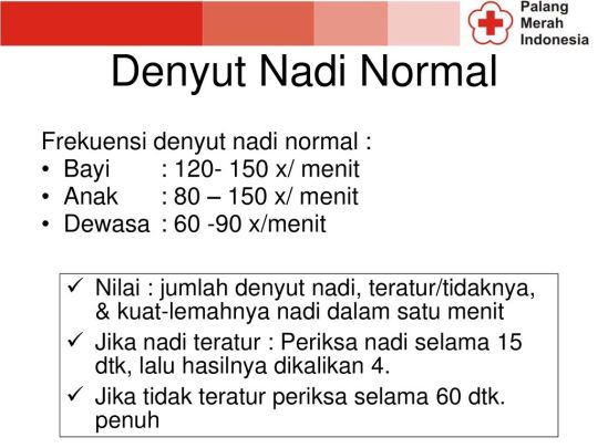
sumber: https://slideplayer.info/slide/13858127/
Cara penggunaan:
1. User mendatangi pulse rate station yang berisi alat pengukuran tersebut.
2. User mengaktifkan perangkat dengan cara menekan tombol power di sebelah layar LCD.
3. User diminta memilih opsi pengukuran. Terdapat 2 opsi dalam pengukuran, yang pertama ada instant check yaitu hanya mengukur dan menampilkan hasil denyut jantung tanpa disertai input data diri dan keterangan hasil pengukuran dan yang kedua adalah complete check yakni user diminta untuk menginput data diri yaitu jenis kelamin dan usia yang dibutuhkan untuk keterangan terkait hasil. Pada opsi kedua user diminta mengisi data diri.
4. User memasukkan tangan ke tempat yang disediakan dan meletakkan jari ke cincin pengukuran.
5. Pengukuran dilakukan.
6. Hasil ditampilkan di layar LCD dan apabila ingin menampilkan hasil di layar ponsel bisa scan QR code yang muncul di layar LCD menggunakan kamera ponsel.
7. Perangkat pengukuran akan menonaktifkan daya secara otomatis setelah dalam posisi idle selama 2 menit.

Sumber: dokumentasi pribadi
Rancangan sistem hardware:
1. Lokasi peletakkan Pulse Rate Station.

Source: Google Maps
PRS diletakkan di 2 tempat yaitu pintu masuk selatan dan utara menuju SARAGA. Masing masing tempat diletakkan 2 station yang satu stationnya berisi 10 perangkat. Pertimbangan peletakkan PRS ini adalah biasanya pengunjung SARAGA memulai lari mereka dari point tersebut (warna merah pada gambar di atas). Sehingga sangat memudahkan pengunjung apabila ingin melakukan pengukuran sebelum dan sesudah kegiatan lari. Jumlah perangkat bisa disesuaikan dengan kebutuhan yang ada, namun pada saat ini saya mengalokasikan sebanyak 20 perangkat di setiap titik dengan pertimbangan agar tidak menimbulkan antrean yang bisa menghalangi jalan.
2. Rancangan station.

Sumber: Dokumentasi pribadi
Gambar di atas merupakan rancangan station. Dilengkapi dengan 10 panel LCD dan kotak penyimpanan sensor agar sensor lebih terjaga. Untuk power supply ada di belakang station.
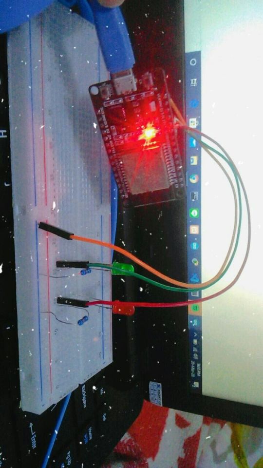
3. Rancangan komponen hardware.

Sumber: Dokumentasi pribadi
Gambar di atas merupakan rancangan komponen perangkat keras yang menjadi ‘otak’ dari alat pengukur denyut jantung. Nantinya ESP32 akan dihubungkan ke power supply yang tersedia di balik station.
4. Rancangan fingertip ring sensor.

Sumber: Google Image Link
Rancangan sistem software.
Gambar di bawah adalah flowchart cara kerja dari perangkat lunak yang tertanam dalam mikrokontroler.

Sumber: dokumentasi pribadi.
Apabila user melakukan scan QR code di ponselnya, maka secara otomatis akan muncul informasi yang sama dengan apa yang ditampilkan di layar LCD.
Pulse Rate Station 2.0 = Pencatatan Latihan Mandiri Otomatis?!
Pulse Rate Station 1.0 adalah rancangan yang telah saya buat untuk mengukur detak jantung serta memberikan informasi apakah hasil tersebut normal atau tidak berdasarkan informasi diri. Mungkin kedepannya bisa dimodifikasi dengan menambahkan fitur mengukur tekanan darah, kadar oksigen dalam tubuh, dan alat ukur lainnya yang berhubungan dengan kebugaran fisik. Bahkan belakangan saya berpikir untuk membuat sistem laporan latihan mandiri secara otomatis menggunakan Pulse Rate Station 1.0 yang saya rancang ini. Karena saya menemui banyak tindak kecurangan yang dilakukan mahasiswa terkait latihan mandiri seperti menulis di kertas latman bahwa ia telah melakukan latihan mandiri untuk lari padahal tidak alias tulman (tulis mandiri), atau melakukan kegiatan lari tapi tidak sesuai dengan anjurannya yang berlari sejauh 2,4 km atau setara dengan 6 putaran, dan masih banyak tindakan illegal lainnya yang tidak diketahui langsung oleh dosen namun itu sangat sering dilakukan.
Mungkin bisa jadi dengan pelaporan latihan mandiri otomatis yang bisa diterapkan di Pulse Rate Station 2.0 (versi kedua dari Pulse Rate Station 1.0) ini bisa menjadi solusi atas ‘kenakalan’ mahasiswa tersebut? Hehe saya harap kedepannya bisa dipertimbangkan oleh pengajar mata kuliah olahraga di ITB karena menurut saya station ini sangat inovatif. Pencatatan latihan mandiri secara otomatis ini sangat mengurangi resiko kecurangan yang dilakukan oleh mahasiswa. Namun okay, nanti saya akan buat rancangan versi 2 nya. Tapi untuk saat ini, saya merasa rancangan Pulse Rate Station 1.0 sejauh ini sudah cukup solutif terhadap masalah yang saya temui yakni kesulitan mengukur denyut jantung.
Terima kasih untuk semua orang yang telah membaca hingga kalimat ini. Semoga rancangan saya bisa direalisasikan di masa yang akan datang atau setidaknya memberikan inspirasi kecil bagi pihak yang membutuhkan inovasi dalam bidang serupa.
Have a nice weekend, peeps!
0 notes
Text
Bluetooth on ESP32
Hello!
This microcontroller comes with build-in Wifi and two kinds of Bluetooth. It’s Bluetooth low energy and Bluetooth classic. It has the same name called Bluetooth but what the difference between them?
Based on this link, the difference between the classic and the low energy is the classic commonly used for streaming voice and data transfer meanwhile the low energy one used for IoT devices that only require periodic data transfer.
So in this project, I will test the Bluetooth is perfectly working or not and combining them with LCD. This project is to write and display the data to the smartphone and also displaying data to the LCD. The data is written in the Arduino IDE’s serial monitor, and the data must appear on the smartphone and LCD. The spoiler for this project is, I’ve tried it last week and it’s working in a good way without any obstacles, alhamdulillaah. Unlike some of my posts before, this project is easy with the rating of difficulty is 1 from 10 HEHEHE.
For this project, I’m looking at the references from this link for Bluetooth low energy and this link for Bluetooth classic. But for displaying to the LCD, I do the same way that I did before (check this link!).
The equipment that I need is:
1. ESP32
2. Jumping wires
3. Laptop with Arduino IDE
4. Smartphone with build-in Bluetooth and installed serial Bluetooth terminal (you can download from play store for Android)
5. LCD Display
The circuit adjustment is the same as my ‘Hello World’ for LCD project:

source: personal documentation

source: https://randomnerdtutorials.com/esp32-esp8266-i2c-lcd-arduino-ide/
Bluetooth Classic
The link is only showing how to print the data in the serial monitor that written on the smartphone. For showing to the LCD, I made some modification for the code and this is the final source code:


source: personal documentation
And here’s the result!
youtube
I’m sorry for the video quality and the brightness:((
Bluetooth Low Energy
The step is the same as the classic one, the difference is this BLE using another code and another library. I forgot to screenshot the code but it’s similar to the code of Bluetooth classic.
Result:
youtube
As I said before, I don’t have any obstacles during this project. I think it’s easy because I only use 1 additional peripheral (it’s LCD), and combine the code with the code for displaying data to the LCD. I hope you can try this as easily as I tried. Bye!
0 notes
Text
Sensor + LCD Project
Hello, fellas!
So in this project, I want to combine my current project (ESP32 with LCD) and the temperature sensor. For this experiment, I’m still using DHT 11 for the sensor, because after I’m comparing with BME280, DHT 11 is much easier. After all, BME280 needs an additional pin to connect to GPIO on the board.
This is the equipment and program that I need for this project:
ESP32
Laptop
Jumper wire (female-female, male-male, female-male)
LCD Display (I’m using 16 x 2 version) with I2C
DHT 11 for the sensor (I’m using DHT 11 with a build-in resistor, a little bit pricey but worth!)
USB Type-A Cable
Breadboard
Arduino IDE with several drivers as I mentioned in my current post (LiquidCrystal_I2C, DHT Sensor Library by Adafruit, Adafruit Unified Sensor)
Patience (HEHEHE I’m kidding but TRUST ME YOU NEED PATIENCE FOR THIS PROJECT)
After collecting all of the equipment, let’s arrange the board by put the wire on the right port. And this is the direction for arranging the circuit:
DHT11
+ : 3.3 V on the ESP32
Out: GPIO 4 (D4 on the ESP32) but you can put the wire to another GPIO pins
- : Ground
LCD Display
GND: Ground on the ESP32
VIN: 5V (VIN pin)
SCL: GPIO 22
SDA: GPIO 21
For this arrangement, I’m using the different ground for DHT11 and LCD Display. Because when I’m making them parallel and put them in one ground pin, my LCD Display can’t turn on. I don’t know why but after I’m putting them separately, the LCD Display turns on and can be used.


The code:
/*********
Rui Santos
Complete project details at https://randomnerdtutorials.com
*********/
#include <Adafruit_Sensor.h>
#include <DHT.h>
#include <LiquidCrystal_I2C.h>
// set the LCD number of columns and rows
int lcdColumns = 16;
int lcdRows = 2;
// set LCD address, number of columns and rows
LiquidCrystal_I2C lcd(0x27, lcdColumns, lcdRows);
#define DHTPIN 14 // Digital pin connected to the DHT sensor
#define DHTTYPE DHT11
DHT dht(DHTPIN, DHTTYPE);
void setup() {
Serial.begin(115200);
dht.begin();
// initialize LCD
lcd.init();
// turn on LCD backlight
lcd.backlight();
}
void loop() {
//read temperature and humidity
float t = dht.readTemperature();
float h = dht.readHumidity();
lcd.setCursor(0, 0);
lcd.print("Temperature: ");
lcd.setCursor(0, 1);
lcd.print(t);
delay(2000);
lcd.clear();
lcd.setCursor(0, 0);
lcd.print("Humidity: ");
lcd.setCursor(0, 1);
lcd.print(h);
delay(2000);
lcd.clear();
}
The stories behind the project:
I’m doing this project for one week and finally work at the end of the week. I found many obstacles to doing this, and I almost post that I can’t do this project. I’m hopeless to be honest HEHE. But after I said, “Okay this is my last trial, after this if it still doesn’t work, I’m giving up. I will post my helplessness on my Tumblr instead.”, THE LCD DISPLAYING THE RIGHT OUTPUT AND I’M BLESSED.
And here’s the result:


So this is my problem for this project:
There’s a GPIO pin that doesn’t work, so I must try to find another good pin and it’s REALLY wasting my time.
The wiring problem is still my problem since the current project. I have some bad wire and I still didn’t separate it with the good one. Maybe if you find the same problem with me, you need to buy a new jumper wire.
Okay, see you on my next project!
0 notes
Text
Trying Hello World with ESP32 on LCD???

Hello!
So, today's experiment is to make a new hello world. In this trial, I’m trying to display hello world on the LCD with the help of ESP32 using Arduino IDE. This experiment according to this link.
For this experiment, I’m using 16 x 2 I2C LCD, but the link said another size can work perfectly too. Equipment that you need for making this hello world is:
1. ESP32
2. Arduino IDE
3. LCD Display with I2C
4. Wires
5. As time goes by you need to install a new library for Arduino IDE but the link explains it well
I managed to run this experiment with MUCH OF OBSTACLE honestly. And this is the list of the mistakes that I’ve faced from this experiment and the solution:
1. The USB cable that I used is unable to transfer data. So the cable is only for charging the device (I mean just for power supply) but the cable can’t transfer any data. The solution is to make sure your USB cable can transfer data well.
2. Make sure you set the right port in the Arduino IDE. For example, I usually use the COM4 port but in this experiment, I didn’t make sure the board is set to COM4 port.
3. I have borrowed my friend’s LCD and only several LCD works well. I don’t know about this case but I think it’s man-made equipment so there must be a problem sometimes. Hehe.
See you on the next project!
Mini spoiler for the next project: I’ll combining this trial with the previous one.

0 notes
Video
undefined
tumblr
The result of temperature and humidity sensors trial.
0 notes
Text
Trying to understand the breadboard with temperature and humidity sensors.
Last week, I’m just trying to use temperature and humidity sensors to ESP32. With expectation, ESP32 will display the temperature and humidity at serial monitor easily. According to the link used as the reference, I think it will be easy to operate. But the expectation is still an expectation. I found problem again. And I think I will always find obstacles during my experience with microcontroller.
Okay let me tell you the equipment I used for this trial:
ESP32 microcontroller
USB Type-A Cable
Temperature sensors (I use DHT 11 with resistor inside)
Breadboard
Male-to-female and male-to-male cable
And here’s my references link: https://randomnerdtutorials.com/esp32-dht11-dht22-temperature-humidity-sensor-arduino-ide/
My first impression after reading the link is “simple”. And I think I won’t have any problem with it but yea, after the series is finished compiled, the IDE response is “Failed to read from DHT sensor!”. And this problem also experienced several teams. But after I asked my friend, she suggests arranging the DHT11 on one side of the board.

As you can see, the breadboard is consists of two sides separated by a little gap in the middle. My friend told me to use only one side for the whole series. And…

This is the wrong installation.

And this is the right one.
(okay i’m still can’t fix this problem so you can check my video at link below):
https://nisarifdah.tumblr.com/post/190747865068/the-result-of-temperature-and-humidity-sensors
YEA!
It works perfectly!
So I’m just realized that I didn’t know my breadboard well. But after this trial, I have new little knowledge about breadboard and might make it easier in the next trial.
See you!
0 notes
Video
undefined
tumblr
Trying to check touch sensor in my ESP32
0 notes