#edfa module
Explore tagged Tumblr posts
Visit Tumblr Blog
Explore Tumblr blogs with no restrictions, modern design and the best experience.
Last Seen Tumblr Blogs


Fun Fact
25% of US internet users with an annual income of $80-100K use Tumblr.
Text

Multi-Core Optical Fiber: Redefining Bandwidth in a Compact Package | Fibrecross
The digital age has ushered in unprecedented demand for high-speed, high-capacity networks. From remote collaboration and cloud gaming to massive IoT deployments, our appetite for data only grows. Traditional single-core optical fibers—while reliable—are straining under this weight. Enter multi-core optical fiber (MCF), a technology that crams multiple light-carrying paths into one thin strand of glass, dramatically boosting capacity without demanding more duct space.
The Essentials of Multi-Core Fiber
Imagine a single-lane road suddenly becoming a multi-lane expressway inside the same tunnel. That’s the core idea: instead of one light-guide at the center, an MCF embeds several—often 4, 7, or 12—within the same cladding. Each “lane” (core) carries its own data stream, enabling space-division multiplexing (SDM) and multiplying total throughput.
Key design points include:
Core Arrangement: Symmetrical patterns (e.g., hexagonal clusters) ensure mechanical stability and uniform performance.
Crosstalk Control: Adequate spacing or refractive-index trenches keep light in its lane, minimizing interference.
Standard Footprint: Most MCFs retain the familiar 125 µm outer diameter so they fit existing cables and connectors—with the right adapters.

Why Networks Are Racing to Adopt MCF
Skyrocketing Traffic Video streaming, virtual reality, and 5G backhaul are pushing fiber links to their theoretical limits. MCF offers a near-term upgrade path without overhauling network routes.
Urban and Subsea Constraints In congested city ducts or undersea trenches, ripping and re-laying cable is prohibitively expensive. Adding cores, not cables, solves the space puzzle.
Energy and Cost Savings Fewer fiber strands and transceivers translate into lower power bills and reduced hardware expenses—an attractive proposition for sustainability-minded operators.
Future-Proofing As networks evolve toward software-defined, spatially multiplexed architectures, MCF becomes a foundational building block rather than a niche experiment.
Technical Hurdles and How They’re Being Solved
Splicing and Alignment Joining multiple cores requires sub-micron precision. Next-generation splicers with rotational alignment and real-time feedback are making installations smoother.
Connectors and Fan-In/Fan-Out Converting between single-core equipment and MCF requires fan-in/fan-out modules. Advances in 3D-printed waveguides and silicon photonics are paving the way for plug-and-play adapters.
Optical Amplification Standard EDFAs serve only one core. Researchers are developing multi-core amplifiers that pump all channels simultaneously, ensuring balanced gain across the fiber.
Standards and Ecosystem International bodies are defining MCF specs for core count, spacing, and performance metrics. As more vendors sign on, compatibility headaches will diminish.

What’s Next for Multi-Core Fiber?
The journey of MCF has only just begun. Here are some emerging directions to watch:
Higher Core Counts Beyond 12 cores, experimental fibers with 19, 36, or more lanes are under laboratory evaluation—each promising exponential capacity growth.
Mode-Multiplexed MCF Combining spatial cores with few-mode transmission inside each core could unlock even greater data densities, albeit with more complex signal processing.
Integrated Photonic Interfaces Photonic chips capable of routing, switching, and amplifying multi-core signals on a single silicon die will accelerate deployment in data centers and metro networks.
Green Networking As operators chase carbon-neutral goals, MCF’s efficiency gains—fewer lasers per bit—will become a core selling point.
Final Thoughts
Multi-core optical fiber represents a paradigm shift: instead of adding more cables, we add more lanes inside the same cable. For network architects wrestling with capacity crunches in crowded cities or deep beneath the ocean, MCF offers a smart alternative—one that leverages existing infrastructure while delivering tomorrow’s bandwidth today.
Whether you’re planning a hyperscale data center interconnect, upgrading metro rings, or building the next generation of submarine links, multi-core fiber deserves a central place in your strategy. Its blend of performance, efficiency, and scalability makes it uniquely suited to tackle the data deluge head-on—without bringing your network to a standstill.
1 note
·
View note
Photo

PON (Passive optical network) based FTTH access network is a point-to-multipoint, fiber to the premises network architecture in which unpowered optical splitters are used to enable a single optical fiber to serve 32-128 premises. FTTH network exploits the low attenuation and high bandwidth of single-mode fiber to provide many times more bandwidth than currently available with existing broadband technologies.
Optical line terminal, optical splitters and optical network terminal/unit are the three components of FTTH access network
OLT (Optical Line Terminal)
The optical line terminal is the main element of the network and it is usually placed in the local exchange. It is the engine that drives FTTH system. Traffic scheduling, buffer control and bandwidth allocation are the most important functions of optical line terminal. Typically, OLT operates using redundant DC power and has at least 1 Line Card for incoming internet, 1 System Card for on-board configuration, and 1 to many GPON cards. Each GPON card consists of a number of GPON ports.
Optical Splitter
The optical splitter splits the power of the signal. That is to say, each fiber link entering the splitter may be split into a given number of fibers leaving the splitter. Usually, three or more levels of fibers correspond to two or more levels of splitters. This enables sharing of each fiber by many users. The passive optical splitter has the characteristics of broad operating wavelength range, low insertion loss and uniformity, minimal dimensions, high reliability, and supporting network survivability and protection policy.
ONT/ONU (Optical Network Terminal/Unit)
ONT/ONU is deployed at customer’s premises. It is connected to the OLT by means of optical fiber and no active elements are present in the link. In GPON, the transceiver in the ONT/ONU is the physical connection between the customer premises and the central office OLT.
The basic components of the GPON FTTH access network are presented and the contribution of each component to the architecture of the FTTH network is addressed. GPON FTTH network architecture is indeed reliable, scalable, and secure. It is a passive network, so there are no active components from the CO to the end user, which dramatically minimizes the network maintenance cost and requirements. FTTH is future proof solution for providing broadband services.
#MUX#SCR#FTA IRD#IRD Modulator#Transcoder#Encoder Modulator#Local Channel Inserter#Hybrid Fiber-Coaxial (HFC)#CATV Transmitter#Splicing Machine#EDFA#OTDR#Internet Of Things(IOT)#Smart Home (Home Automation)#Home Automation#Outdoor Camera#Video Doorbell#CCTV Camera#Smart Door Lock#Fiber To The Home (FTTH)#OLT#ONU#Other Products#HDMI Cable#Audio Video RCA Cable#CAT-6 Cable#RG-6 Cable#RJ-45 Connector#5/12 Volt Adapter#Stereo to RCA Cable
0 notes
Text
Whether to Use EDFA Amplifier in Long WDM System Or Not?
Currently, utilizing WDM technology to deploy the optical network has received widespread attentions, which enables higher capacity for data transmission. However, the technology is also limited by the transmission distance. When deploying a long WDM system, the signal power would still become weak due to the fiber loss. In order to address the issue, using EDFA amplifier to directly enhance the WDM signals would be a good choice for current and future optical network needs. The optical network combining WDM technology and EDFA module together can transmit multiple signals over the same fiber, at lengths up to a few hundred kilometers or even transoceanic distances. To better know how does EDFA amplifier work in the long WDM system, let’s learn the EDFA amplifier knowledge and analyze the performance of WDM system bonding with the EDFA module.
Introduction to EDFA Amplifier
EDFA amplifier, also referred to as erbium-doped fiber amplifier, is basically composed of a length of Erbium-doped fiber (EDF), a pump laser, and a WDM combiner. When it works, the pump laser with 980 nm or 1480 nm and the input signal around 1550 nm can be combined by the WDM combiner, then transmitted and multiplexed into the Erbium-doped fiber for signal amplification. The pump energy can be transmitted in the same direction as the signal (forward pumping), or the opposite direction to the signal (backward pumping), or both direction together. And the pump laser can also using 980 nm or 1480 nm, or both. Taking the cost, reliability and power consumption into account, the forward pumping configuration with 980nm pump laser EDFA amplifier is always the first choice to enhance the signals for a long WDM system.
Analysis of WDM Network Without EDFA Amplifier
Before analyzing WDM network deployed with EDFA amplifier, it is necessary to know the basic configuration of an original WDM network, as shown in the figure below. We can learn that four signals from different channels are combined by the optical combiner. And then, the integrated signals are transmitted through an optical fiber. Thirdly, the signals are split into two parts by the splitter. One part passes through the optical spectrum analyzer for analyzing signals, and the other one goes through the photo detector to be converted into electrical signal and then be observed by the electrical filter and scope. However, in the process, the signal power gets highly attenuated after being transmitting at long distance.

Analysis of WDM Network Using EDFA Amplifier
By using the EDFA amplifier, we can easily overcome the attenuation of long WDM network. From the following figure, we can learn that EDFA amplifiers act as booster amplifier and pre-amplifier to enhance the signal, so that system will no longer suffer from losses or attenuation. Therefore, if you need to deploy a long WDM system, it is highly recommended to deploy the EDFA amplifiers in the system that features flat gain over a large dynamic gain range, low noise, high saturation output power and stable operation with excellent transient suppression. It is an undoubtedly ideal solution with reliable performance and relatively low cost to extend the WDM network transmission distance.

Conclusion
It is well know that the signal power would be greatly attenuated when the transmission distance is long enough. Hence, when deploying a long WDM network, it is definitely necessary to use the EDFA amplifier to enhance the signal strength, allowing for the long transmission distance. As a preferable option, the EDFA amplifier with very low noise is relatively insensitive to signal polarization and easy to realize signal amplification.
0 notes
Text
GGE-20FT CATV & SAT IF Mini Optical Transmitter
General Description

GGE-20FT-1310, GGE-20FT-1550 GGE-20FT series optical transmitter, adopt high linearity DFB laser, modulated directly, It can transmit 45-2600MHz digital TV. Optical operating wavelength is optical as 1310nm or 1550nm. 1550nm optical transmitter, ITU standard wavelength can be selected, suitable for DWDM to realize network-upgrading and capability-expansion. Meanwhile, add EDFA can amplify the optical power, compatible with any FTTx PON technology. Performance Characteristics l Smart digital display & control monitor system, simplified operation. l Combined RF in port or separate CATV/SAT IF RF in port can be customized. l High band wide 47-2600MHz. l Suitable for digital TV and satellite TV application. l 1310nm/1550nm optical output power from 2~10mW optional. l 1550nm Tx can be amplified by EDFA, YEDFA to cover large scaled FTTH. l Alumininum casing, good heat dissipation and performance. l Compatible with any FTTx Pon technplogy. Application、

echnical Specification Item GGE-20FT-1310/GGE-20FT-1550 Optical Wavelength (nm) 1300±10 or 1550±20 Wavelength stability (pm/℃) -1~0 SMS (dB) 35 Optical output power (mW) 2~10 Connector type SC/APC or FC/APC CATV Frequency range (MHz) 47~865 CNR (dB) ≥51 Flatness (dB) ±0.75 C/CTB (dB) ≥65 C/CSO (dB) ≥65 Output Impedance(Ω) 75 Output return Impedance(dB) >16 Input range (dBμv) 15~25 (AGC) SAT IF Frequency Range(Mhz) 950~2600 IF Output Power(dBm) -40~-25 Flatness(dB) ±1.50 CNR(dB) 29 CSO(dB) -36 CTB(dB) -36 To LNB voltage(V) 13/18 To LNB Max. Current(mA) 300 General Parameter Power Voltage(VDC) 24 (DC Adaptor) External Solar Battery Panel 29~36VDC 120W(Battery) Charger Socket 24VDC Charger Power consumption(A) 0.5 Size(L*H*W) 210*150*60 Package 1piece/Box 10pcs/Ctn. Gross Weight(Kg) 14.5/Ctn Ctn. Dimension(cm) 53*37.5*29.2 Read the full article
1 note
·
View note
Text
FBT Splitter: How Much Do You Know?
FBT Splitter is responsible to distribute optical signals from central office to multiple premise locations. This article will provide some knowledge about FBT splitters.

What is FBT Splitter?
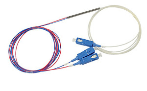
A fused biconical taper (FBT) splitter is based on traditional technology to weld several fibers together from the side of the fiber. Fibers are aligned by heating for a specific location and length. Because the fused fibers are very fragile, they are protected by a glass tube made of epoxy and silica powder. And then a stainless steel tube covers the inner glass tube and is sealed by silicon.
FBT Splitter Types
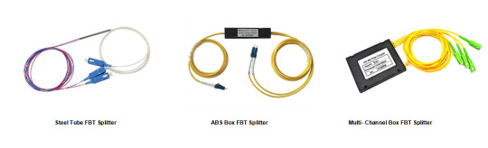
FBT splitter is available in the market in steel tube, ABS box, and multi-channel box types. The steel tube type is a 1x2 FBT splitter with a different coupling ratio, has 900um loose tube protection, and is provided with a selection of connectors (SC/LC/FC, etc). The ABS box type is a 1x2 FBT splitter module packed in an ABS box with ruggedized fiber jackets of 2mm and up to 3mm with SC/APC fiber connectors terminated. Multi-channel box type like 1x3 FBT splitter has 1x3 single mode single window 3.0mm loose tube fiber coupler that can split the optical signals into 3 parts, and the coupling ratio can be customized.
Features and Benefits
FBT splitter provides high stability, high reliability, low insertion loss, low polarization dependent loss, wide operation wavelength, wide operation temperature, compact size, low cost, easy-to-produce, and customizable splitter ratios.
Applications
FBT Splitter is used in an optical communication system, online monitoring system, telecommunication, data centers, FTTx, FTTH, PON, LAN, WAN, CATV, EDFA, local loop, testing equipment, fiber sensors, etc.

Conclusion
To sum up, the FBT splitter is widely used on fiber in different places on PON systems. Low cost and high reliability and high stability are the main features. Sun Telecom specializes in providing one-stop total fiber optic solutions for all fiber optic application industries worldwide. Contact us if any needs.
1 note
·
View note
Text
Advantages Of Semiconductor Optical Amplifiers
Introduced in the 1990s, the optical amplifier gave new dimensions to the regenerator technology and opened new opportunities to the WDM (Wavelength Division Multiplexing) technology as well. Mainly, it is used for directly amplifying an optical signal without having to convert it into an electrical signal.
As you may already know, there are several kinds of optical amplifiers including erbium-doped-fiber amplifiers (EDFAs), Raman amplifiers, and the popular semiconductor optical amplifiers (SOAs).
Semiconductor optical amplifiers make use of a semiconductor as a gain medium. These are specially designed to increase the optical launch power in order to compensate for the loss of optical devices in general applications.
SOAs are frequently used in telecommunication systems as fibre-pigtailed components that are capable of generating gains of a maximum of 30 dB and usually operate at signal wavelengths ranging from 0.85 µm to 1.6 µm.

Advantages of SOAs:
Semiconductor optical amplifiers are electrically pumped and are small in size, making them highly efficient.
They are less expensive as compared to other types of optical amplifiers like the Erbium-Doped Fiber Amplifier (EDFA). Also, they can be easily used in modulators, semiconductor lasers, etc.
SOAs are capable of conducting all types of non-linear operations like cross-phase modulation, cross-gain modulation, four-wave mixing and wavelength conversion.
Semiconductor optical amplifiers can be easily run with a low-power laser.
To know about the disadvantages of SOAs, check our blog: Advantages And Disadvantages Of Semiconductor Optical Amplifiers.
0 notes
Text
PM EDFA MP3B Module Mini EDFA
PM EDFA MP3B Module Mini EDFA
This PM EDFA module supports the following features:
Low noise figure
High stability and reliability
High saturation output power
High precise APC,ACC Circuit
Compact mechanical and circuit structure
Intelligent temperature control system
Power consumption and hot radiation reduce 30% less than common products
OEM is available
0 notes
Text
What is Fujikura 90S Fusion Splicer?
The company is proud to announce the latest development of the splice with the launch of the new Fujikura 90S.

Over the past 30 years, Fujikura has been at the forefront of the design, development and manufacture of splice, and is widely regarded as a world-class leader in the field of splice.

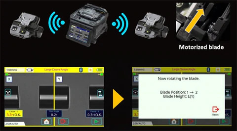
The Fujikura 90S Fusion Splicer is a core alignment fusion splicer setting a new standard in the market for fusion splicing. The Fusion splicing machine 90S is packed with a whole host of new and enhanced features specifically developed with the objective of enabling the user to work faster with higher precision. Overall splice process time has been significantly reduced. This has been achieved with a combination of improvements to the reaction time of the automated wind protectors and automated heater, new fibre retention clamps, improved universal sheath clamps and a redesigned internal structure that matches the protection sleeve to the fusion splice point which enables splicing to be achieved without the need of the user to touch the Fujikura Splicer 90S once the process has started.
The Fujikura Splicing Machine 90S is the latest core alignment splicer from Fujikura. It’s designed to give you high quality splices and to stay in the field. The Fujikura 90S splicing machine kit solves common problems seen in the field today, from splicing poor quality legacy fiber to automated equipment maintenance and upkeep.

The Fujikura 90S can be utilized in any field splicing application seen today:bend-insensitive fibers in drop cables, long-haul terrestrial andsubmarine LEAF fibers, loose buffer fiber, splice on connectors, and thelist goes on.

The speed and accuracy of the Fiber Optic Splicer 90S even makes it suitablefor certain production and specialty environments, where high output,tight packaging, and low loss requirements are needed. Regardless yourscenario, the Fujikura Splicer 90S is designed to keep you going with an extended batterylife of 300 splice and heat cycles, and by alleviating the need fortraditional operation tasks such as; frequent arc calibrations, cleaverblade rotations, cleaver usage tracking, and manual splicing operationswith its multiple automated and ease-of-use features.
A redesigned work tray, cooling tray, and optional cable clamp make the 90S Fusion Splicer kit more versatile than any of its predecessors in adapting to varying work conditions and environments. In addition, if you are splicing loose buffer fiber, there is no longer a need to purchase and swap out with an additional sheath clamp. Now, a universal sheath clamp that handles both loose and tight buffer fiber is standard.
90S Fusion Splicer Applications: Distribution fiber repair Long-haul network installation Field termination with splice-on connectors Access network installation Fanout kits, pigtails and splice cassettes OSP cable installation and repair Optical modules – splitters, couplers, MUXs, EDFAs and attenuators
Features: Market leading high precision and accurate core alignment technology with advanced image processing. Improved automatic wind protector design which reduces overall splice time but can also be used manually. Patented easy splice protector positioning system. Fibre Retention clamps. Universal sheath clamps for standard 250 um fibre as well as 900 um loose tube fibre types. A completely redesigned multi-function carry case and workstation. Enabled with Fujikura’s unique “Active Blade Management Technology” with new capability to link up to two CT50 cleavers simultaneously. Tool-less replaceable electrodes. High capacity lithium-ion battery (up to 300 splices). Touch screen.
https://www.splicermarket.com/blogs/news/what-is-fujikura-90s-fusion-splicer
#Fujikura 90S Fusion Splicer#Fusion splicing machine 90S#Fujikura Splicer 90S#Fujikura Splicing Machine 90S#Fujikura 90S#Fiber Optic Splicer 90S#90S Fusion Splicer#90S
0 notes
Text
Fiber Optical Isolators and Their Types
Fiber Optical Isolator is a passive optical component used in fiber optic communication. It is a magneto-optic device that allows the transmission of light in only one direction. Optical isolators are typically used to prevent unwanted feedback or back reflection, particularly in lasers. It stops the scattering light from reaching sensitive components, which can damage the laser source and cause unexpected laser problems such as frequency shift, mode hop, and so on. Isolators can reduce these effects when used as an indispensable device in fiber optic systems.
Fiber optical isolators are used in a range of fiber optical applications in industrial and laboratory settings. They can be used in fiber optic lasers, fiber optic communication systems, Fiber optic amplifiers, and optical module interfaces for specific applications.

Construction of Fiber Optic Isolators
Fiber optical isolators have three main parts:
· An Input Polarizer
· A Faraday Rotator with Magnet
· An Output Polarizer
The input polarizer allows only linearly polarized light to pass through it to the Faraday isolator. The Faraday rotator rotates the input light by a certain angle before transmitting it to the output polarizer. The Transmitted light in the forward direction pass unimpeded, however, the optical isolator doesn’t allow the light in the reverse direction to pass through. the Light in the reverse direction is either absorbed or reflected back. The input polarizer, Faraday rotator, and output polarizer work together to allow the normal transmission of light signals. There are mainly two operation modes of fiber optical isolators – forward mode and backward mode, depending on the direction of light signals.
Types of Optical Isolator
Fiber optical isolators are of three types:
Polarized Optical Isolator: It uses a polarization axis to ensure light transmission in one direction. The transmitted light propagates in the forward direction freely, while the isolator blocks any light to travel back. Polarized optical isolators are further classified into dependent and independent polarized optical isolators for different types of applications.
Composite Optical Isolator: It is a type of independent polarized optical isolator and is used in EDFA optical amplifiers. Since the EDFA amplifier consists of many components including wavelength-division multiplexer, erbium-doped fiber, pumping diode laser, and many more, the optical isolator used to transmit light signal in the system is named as composite optical isolator.
Magnetic Optical Isolator
It is a polarized optical isolator with the stressed magnetic part of a Faraday rotator. Faraday rotator is a magnetic crystal under a strong magnetic field to change the polarization of the transmitted light with the Faraday effect.
A fiber optical isolator is a key passive component used in laser transmitters and amplifiers for stable light signal transmission. It eliminates unnecessary light and allows light transmission in only one direction for higher performance. You can get fiber optical isolators in different configurations for your fiber network.
0 notes
Photo

Microtech infocom is in business of set top boxes,internet of things,catv products,hfc,home automation We are also provide digital head end,encoder,mux,encoder modulator,local channel inserter,fta ird,ird modulator,qam,transcoder,transmitter,edfa,otdr,splicing machine,smart home,olt,onu,outdoor camera,vidoe doorbell,hdmi cable,adapter,connector,cctv camera,usb socket charger,remote
#microtechinfocom#MicroTech InfoCom#Solution#Digital Head End Solution#FTTH broadband Solution#IPTV and OTT Solution#Telecom solutions#Set Top Boxes#MPEG-4 SD DIGITAL SET TOP BOX#MPEG-4 HD DIGITAL SET TOP BOX#Android and OTT Box#CATV Products#Encoders#IP QAM#MUX#SCR#FTA IRD#IRD Modulator#Transcoder#Encoder Modulator#Local Channel Inserter#Hybrid Fiber-Coaxial (HFC)#CATV Transmitter#Splicing Machine#EDFA#OTDR#Internet Of Things(IOT)#Smart Home (Home Automation)#Home Automation#Outdoor Camera
0 notes
Text
The system structure of OTN equipment
Hi, everyone!
Today I'm going to introduce you about the system structure of Huawei OTN equipment
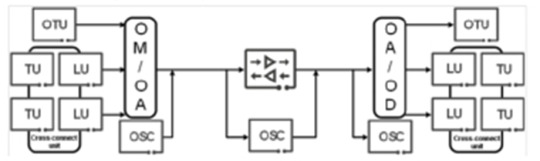
The OTN device mainly contains five parts, they are OTU(Optical Transponder Unit), XCS(Cross-connection Unit), OMU/ODU(Optical Multiplex Unit/Optical Demultiplex Unit), OA(Optical Amplifier) and OSC/ESC(Optical/Electrical Supervisory Channel).
The OUT boards convert the non-standard wavelength into the standard wavelength specified by the ITU-T. The system uses the optical/electrical/optical (O/E/O) conversion. That is the received optical signal is converted into the electrical signal by using the photodiode PIN or APD, and then the electrical signal modulates the laser of the standard wavelength, in this way, a new optical wavelength signal that meets requirements is obtained.
The XCS boards receive data from service boards (line boards and tributary boards), cross-connects ODUk(k=0, 1, 2, 2e, 3, 4, flex)/VC-4 service signals at the electrical layer, and then transmits the signals to service boards for service cross-connection.
The OMU boards ware used at the transmit end. Each input port of the OMU boards inputs one pre-selected wavelength of optical signals, and the input wavelengths are output through the same output port. The ODU boards are used at the receiving end. They have one input port and multiple output ports to classify signals of different wavelengths.
The OA boards can directly amplify optical signals and provide real-time, high-gain, broadband, online, low-noise, and low-loss all-optical amplifiers. Currently, EDFAs and FRAs are commonly used, erbium-doped fiber amplifiers (EDFAs) are widely used as preamplifiers, line amplifiers and power amplifiers in long-distance, large-capacity, and high-speed fiber communication systems.
The OSC/ESC boards are used to monitor the WDM optical transmission system. ITU-T recommends that you use the 1510 nm wavelength with a capacity of 2Mbit/s. The receiver sensitivity (better than –48dBm) is normal when the rate is low. The optical signals must be dropped before the EDFA and added after the EDFA.
0 notes
Text
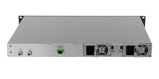
GGE-14EARF Series RF Input Erbium fiber amplifier
GGE-14EARFxx Series RF Input Erbium-doped Optical Fiber Amplifier Performance Characteristics Built-in Optical power APC circuit and laser ATC circuit ensures long life and stable working of the laser. Direct modulated 1550nm optical transmitter integrated with EDFA, together with the parameter optimization, makes debugging steps more simplified. Built-in microprocessor monitors the laser working state. LCD screen shows working parameters. Option status monitor transponder meets GB standard, and compatible with the SCTE HMS standards, which can realize SNMP network management monitoring function. Aluminum structure plug - in switching power supply works under 86 ∽ 265Vac voltage or -48V DC power supply. And cold and hot backup of dual power supply is optional.

Technical Specification Technical Data GGE-14EARFxx Wavelength 1540-1565nm Input power range -5dBm~10dBm Output power range + 13dBm~+26dBm Noise figure < 5dB Optical connector FC/APC&SC/APC FC/PC&SC/PC Return loss ≥ 45dB RF range 47~862MHz&1000MHz RF AGC range ±10dB RF input signal level 75~95dBuV CNR >51.0dB Power supply voltage AC90-265V&DC-48V(DC-30V~72V) Flatness ±0.75dB Optical output power stability ±0.05dB RF input impendence 75Ω Return loss >16dB(47~550)MHz&>14dB(550~750(862)MHz Consumption ≤ 30W Work temperature -5℃ ~+55℃ Storage temperature -30℃ ~+70℃ Relative humidity Max95% no Condensing Product size 423x330x45mm SNMP interface RJ45(Support Web and SNMP) Product weight 3.75kg Package weight 4.3kg Carton weight 10kg(2 pcs) Read the full article
0 notes
Text
How to Realize 100KM DWDM Network With FMT 4000E
Nowadays, DWDM technology has been one of the most commonly used technology in optical transport network (OTN) applications due to the increasing bandwidth need of telecommunication providers. Faced with unpredictable traffic requirements and increasing bandwidth demands, FS has developed a new standardized optical transport solution, which called FMT WDM transport platform. And this FMT WDM transport platform is divided into four specific series according to different transmission distance, including CWDM solution FMT 1800, DWDM solution FMT 1600E, 4000E, 9600E. In this post, we will take FMT 4000E optical transport platform as an example to illustrate how does this transport platform realizes 100km network connections and its advantages.
What Is FMT 4000E DWDM Network Transport Platform?
As mentioned above, FMT 4000E DWDM network transport platform is one type of the FMT WDM transport platform series. This optical transport platform is a 4U managed chassis. It is equipped with 16 full-size slots and optical layer modules and a wide range of intelligent services modules can be installed in these slots. Equipped optical devices in FMT 4000E will be illustrated in detail in the following part.


Currently, FS has developed two versions FMT 4000E, but these two versions has different transmission. One version can support 160km transmission, while another can support 100km transmission. And this post will focus on FMT 4000E for 100km. This platform can achieve 100km end-to-end dual fiber bidirectional transport and support up to 40 wavelengths from C21-C60 at 100GHz. In addition, this optical transport platform can be applied in metro/regional networks, such as CATV, FTTH/PON, xDSL triple play services, GSM/3G mobile services, business customers storage services and so on.

How Does the DWDM Network Work By Using FMT 4000E

From the above topology, we can find that the optical signal from the switch will be sent to 40CH DWDM MUX DEMUX at Site A for wavelength division multiplexing. And then the optical power will be lowered by using optical attenuator. And the dispersion will be compensated by DCM. When this process is finished, the booster amplifier (BA) will improve the optical power and extend the transmission distance. After 100km fiber transmission, we need to amplify the signal by using pre-amplifier (PA) and then the optical signal will be compensated by DCM again. At this time, the optical signal will be sent to 40CH DWDM MUX DEMUX at Site B for demultiplexing again. Finally, the optical signal will be sent to the switch.
Why Choose This FMT 4000E DWDM Transport Platform?
This FMT 4000E DWDM transport platform has flexible networking because it is equipped with intelligent DWDM MUX/DEMUX, integrated with DWDM EDFA and DCF-based DCM system management. This platform has high channel density because it has up to 40 DWDM channels. And this platform can achieve 100km end-to-end dual fiber bidirectional transport when the fiber link loss is 0.25dB/km and the fiber type is G.652D. In addition, this platform has monitor online management software, which can allow operators and administrators to monitor the performance of the whole network. When the urgent accident occurs, this network management system can notify the user so as to ensure the safety of the network. This system can also provide real-time management for local and remote network. Besides, it will send email to inform you of the performance of the network.

Conclusion
This FMT 4000E optical transport platform will be a cost-effective option for l00km transmission due to its better network performance and centralized network management. And FS is always striving for meeting your specific needs and this product is customized for each customer. If you are interested in this product, please contact us via [email protected].
0 notes
Text
When Microseconds Equate to Millions of Dollars – Latency And Optical Networks for High Frequency Trading (HFT)

High frequency trading (HFT) firms continue to make the news with demand for ultra-low latency (ULL) networks. The recent announcement by ZAYO Group that an HFT firm had signed up for their ULL network, including dark fiber and a wavelength solution, is just one example. In this article, the effort by the industry to mitigate latency in support of HFT and other low latency applications is examined.
About high frequency trading
HFT is a process by which very fast processor computers and sophisticated algorithms are used to transact huge amounts of stock trades in fractions of a second. The computer algorithms analyze multiple market trends and automatically execute orders based on those trends. Professor Jonathan Macey of the Yale School of Management likens HFT to a motorcyclist, who after noticing a truck/lorry driver speeds up to buy all the fuel along the highway. When the truck driver gets to a gasoline/petrol station, the motorcyclist sells him fuel at a premium knowing that the trucker does not have any other options. While the profit realized by executing a single trade is minuscule, high frequency traders make huge profits by executing a large number of trades. The key to success in this trading game, which has been criticized as parasitic, is speed. Speed that comes with computer processing power to analyze market trends and the speed of executing trades ahead of anyone else. (adsbygoogle = window.adsbygoogle || ).push({}); For more on high frequency trading you can also read Michael Lewis’s book, Flash Boys: A Wall Street Revolt. While some traders have been able to drastically reduce latency by collocating with the stock exchange and optimizing the server processing speed, some must access more than one exchange such as Chicago and New York or London and Frankfurt. As a result, optical networks connecting financial institutions between these locations must be optimized for latency. The most important contributors to latency in an optical network are the transmission fiber, dispersion compensating fiber and the process of optical to electrical conversion or vice versa. We will look at latency and its mitigation in these components and processes.
Latency in optical fibers
Optical fiber is the most important contributor of latency in a long-distance optical communication network. The length of the optical fiber represents the distance traveled by communication signals from one point to another. While the light travels at a speed of 299,792km/s in free space, the speed is reduced to about 204,190km/s in a standard single mode (ITU-G.652 compliant) fiber. The ratio of the free space speed to speed in fiber is the group refractive index of the fiber which is 1.4682 in this case. The above speeds translate to latencies of 3.34µs/km in free space and 4.90µs/km in the standard single mode fiber. While these values are insignificant for most communication applications, they have a profound impact on latency sensitive applications such as the HFT discussed above. The optical network engineer must perform meticulous calculations and procure the lowest latency fiber available to minimize the overall latency of the network or link.\ A number of manufacturers are optimizing their manufacturing processes to reduce latency, even if it is by a tiny amount. The following table shows the performance of two of the industry’s leading fiber optic brands. While the latency values for these fibers look almost the same, the difference in latency between the two extremes translates to 21µs over 1,000km, a significant value in HFT. Even when traders are collocated with the stock exchange servers, they still put an effort to squeeze out whatever latency they can to get an urge over the competition. With HFT, researchers working on hollow core, photonic crystal fiber (PCF), have found an extra incentive for their work. When commercialized, these fibers could play a pivotal role in HFT and other low latency applications. Photonic crystal (or photonic band gap) fiber is a new type of fiber based on a special class of optical medium with periodic modulation of refractive index. The structure of a hollow core fiber is shown in the picture.

Because of the absence of glass in the core, light in a hollow core fiber travels close to the speed of light in a vacuum – significantly reducing the latency. Researchers from Infinera, Molex, Lumentum and OFS Fitel have demonstrated that hollow core fiber can reduce latency by 30%. See their publication on Researchgate - Transmission of Commercial Low Latency Interfaces over Hollow-Core Fiber.
Latency in dispersion compensating fiber
One important impairment that occurs in optical fibers in long distance optical networks is chromatic dispersion. A phenomenon caused by the wavelength dependence of refractive index, chromatic dispersion (or simply dispersion) causes the broadening of digital pulses. The transmission fiber must be compensated for dispersion before pulse broadening result in the interference of adjacent symbols and distort the signal. The compensating modules are typically inserted on transmission spans between erbium doped fiber amplifiers (EDFAs) – see illustration.

Typical dispersion compensating modules consist of special type of optical fiber with negative dispersion relative to the transmission fiber. The length of the dispersion compensating fiber introduces additional latency in the network. A typical DCF module required to compensate 80km of standard (ITU-G.652) fiber at 1550nm introduces at least 60ns of latency in the network. With multiple spans on a link, the latency quickly adds up. Non-zero dispersion shifted fiber (NZDSF) such as ITU-T G.655 or ITU-T G.656 fiber is sometimes used to reduce the number of DCMs in the network. NZDSF has significantly lower dispersion in the C-band (around 1550nm) transmission window and requires fewer compensating modules and therefore it enables lower latency networks. As an alternative, dispersion compensating Bragg gratings (FBG) are used for compensation because they introduce negligible latency in the system. A FBG is a fiber based device that reflects light due to the modulation of its core refractive index. Light propagating in the grating is reflected if its wavelength matches the periodicity of the core modulation. Selective reflection of components of light at different positions along the grating is used to compensate for incoming high dispersion light. See the article, Fiber Bragg Gratings: A Versatile Approach to Dispersion. Because Bragg gratings are significantly shorter than dispersion compensating fiber, they introduce significantly less latency.
O-E or E-O conversion and latency
In certain cases, it is inevitable that transmission signals are converted from electrical to optical and vice versa. The conversion process introduces a delay which manifests itself as network latency. Transponders and muxponders are some of the network components that operate on O-E or E-O conversion. A transponder takes a short reach LAN optical signal, converts it to electrical and then back to optical while modifying it to a specific DWDM wavelength for transmission over a long distance. A muxponder, on the other hand, takes low transmission speed signals, multiplex them together into a higher speed signal with a specific DWDM wavelength. Both transponders and muxponders can introduce significant levels of latency in the network, up to 10µs. Manufacturers are making every effort to improve their manufacturing processes to reduce the latency.
Summary:
While several applications such as VoIP and gaming are requiring improvement in network latency, it is the high frequency trading application that is demanding the most stringent latency specifications. The industry is focusing on different parts of the optical communication network to reduce latency. A lot of focus to improve latency is on transmission fiber, dispersion compensating fiber and E-O and O-E conversion. For in-depth discussions on optical networking, join a fiber optic training class near you. Read the full article
0 notes
Text
SDH Single Channel Fiber Amplifier EDFA MP31 Series
SDH Single Channel Fiber Amplifier EDFA MP31 Series
Product Introduction
This optical amplifier is high stability output EDFA. The key components of the product is the high reliability multimode PUMP laser. A unique APC (Automatic Power Control) and ATC (Automatic Temperature Control) circuit ensure the high stability and reliability output power, and the unique optical circuit design ensures the excellent optical performance.The high stability and high precision MPU system ensure that the control, adjustment and monitor are intelligent and user-friendly.
System Function Diagram
This DWDM EDFA module supports the following features:➢ Low noise figure➢ High stability and reliability➢ High saturation output power➢ High Precise APC, AGC, ACC Circuit➢ Compact mechanical and circuit structure➢ Intelligent temperature control system: power consumption and hot radiation reduce 30% less than common products➢ OEM is available
0 notes